Multiple electromagnetic qualification measurements have been performed at Sandia on two types of cruise missiles that carry the W80.
The measurements are part of the W80 Stockpile Lifetime Extension Program (SLEP). SLEP is an extensive qualification program to ensure that the W80 meets its operational and nuclear safety requirements in a wide range of environments.
The electromagnetic qualification program includes testing a refurbished W80 under a variety of electromagnetic conditions. These include simulations of friendly and hostile radio frequency transmitters, electromagnetic pulse, nearby and direct-strike lightning, accidental contact with electrical power lines, and electrostatic discharge.
The electromagnetic qualification program started by characterizing the behavior of the cruise missiles that carry the W80.
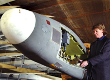
Project lead Matthew Higgins (1653) says it is important to characterize the payload bays and warhead interface cables of the Air Launched Cruise Missile (ALCM) and Advanced Cruise Missile (ACM) because the W80 spends time mounted in the cruise missiles for logistical operations and remains in the missile from carriage on a B-52 to launch and delivery.
“The transfer function measurements will help define further qualification tests in which W80-3 electrical systems will be tested,” he says.
W80 refers to the current stockpile weapon system. The W80-3 refers to the upgraded system being developed for the Stockpile Lifetime Extension Program. The measurements looked at electromagnetic leakage into the payload bays and interface cables of both missiles. The W80-3 shipping container has also been tested, and the W80-3 itself will be tested next.
The electromagnetic transfer function testing determines the leakage of electromagnetic energy into a test object. Using the external threat environments as defined in the W80 stockpile-to-target sequence, the exact amount of leakage can be calculated over a wide range of frequencies.
“With the cruise missile data, we can calculate the leakage into the W80-3 through the missile,” Matthew says. “While it might seem intuitive that a cruise missile would provide some protection, this is not necessarily the case. People tend to assume that metal structures provide sufficient shielding from electromagnetic environments. In reality, the metal structures typically have penetrations, such as control cables in a missile, and openings, such as engine inlets and outlets.”
In addition, cruise missiles have quite a few cables, which can act as antennas that can pick up energy at certain frequencies. Small details such as cable shield terminations can have a big impact on the leakage into an object.
Shielding effectiveness is measured to determine how much electromagnetic energy gets into the missile payload bays. To do this, Sandia engineers exposed the missile to electromagnetic radiation (EMR) over a wide range of frequencies and measured the electric field strength outside the missile and, simultaneously, inside the payload bay. The ratio of the field strength inside the payload bay versus outside the missile is described as shielding effectiveness. A well-shielded enclosure helps protect internal electronic packages from inadvertent malfunction or damage due to exterior EMR.
Energy can also couple into the missile cabling system, which can then create voltages on internal cable wires. In the right circumstances, this voltage can be delivered straight to the W80. To determine the degree of cable coupling, engineers expose the missile to EMR and measure the cable pin voltages. These types of measurements are called effective height, a quantity similar to the effective area of antennas. The less energy that couples into the missile cable, the lower the voltages induced inside the weapon.
The measurements of shielding effectiveness and effective height are carried out in two of Sandia’s RF facilities, the Electromagnetic Environments Simulator (EMES) in Tech Area 1 and the Mode-Stirred Chamber in Tech Area 4.
Low-frequency testing (100 kHz to 250 MHz) is performed at EMES and high-frequency (220 MHz to 40 GHz) is done in the Mode-Stirred Chamber. The two facilities are needed because of the wide range of frequencies required for weapon testing.
“It has been to our advantage that for weapon-related testing, both facilities are vault-type rooms,” says Matthew.
The Mode-Stirred Chamber is essentially a broadband microwave oven, where the fields are deliberately mixed to uniformly bathe a test object in electromagnetic fields. The advantage of this method is that every penetration in a test object will be exposed in a single test run. The disadvantage is that because all potential leakage points are exposed at once, it is difficult to know sometimes where the dominant leakage point is.
“We will find out if it ‘leaks’ and at what frequency, but we may not be able to say where it is leaking from,” Matthew says.
EMES is essentially a building-sized coaxial cable, called a transverse electromagnetic, or TEM cell. Like a coaxial cable, it has a center conductor and a return conductor surrounding it. At EMES, the center conductor is in the middle of the structure, 13 feet away from the return conductor at its highest point. While the Mode-Stirred Chamber bathes a test object in all directions, EMES produces a vertically polarized plane wave that travels the length of the cell like a two-dimensional sheet across a test object. To get a good characterization of a test object in EMES, it is usually desirable to make measurements of a test object rotated in several orthogonal orientations. The main advantages of EMES are its large size and the ability to test at frequencies all the way down to 0 Hz (DC static fields).