Stress Strain Plate
Problem Description
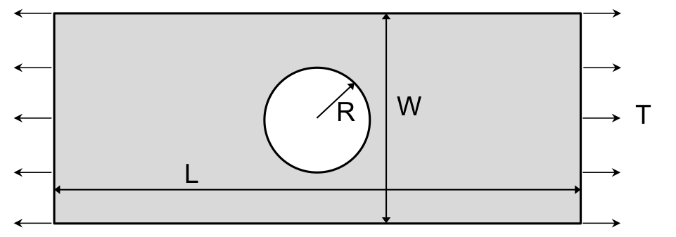
Fig. 1 Plate with hole problem definition.
The purpose of this problem is to exemplify how to apply boundary conditions that approximate plane strain and plane stress conditions in a three-dimensional model. A plate with a hole under uniform tensile loading is considered (Fig. 1) with length L=10.0, width W=4.0, variable thickness 2t, and hole radius R=1.0. The plane strain condition means the out-of-plane strain components are negligible, and the plane stress condition means the out-of-plane stress components are negligible. The former is representative of stresses at mid-thickness of a ‘thick’ plate and the latter is representative of stresses through the thickness of a ‘thin’ plate. This problem is run using implicit quasi-statics.
Loading and Boundary Conditions
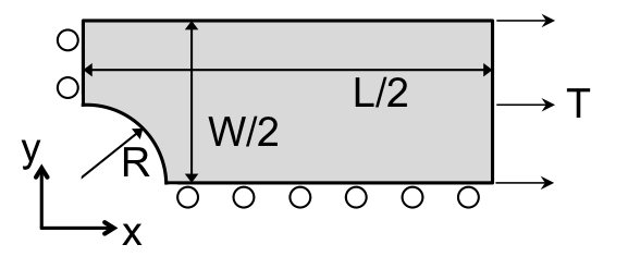
Fig. 2 Plate with hole model.
For computational simplicity, only one-eighth of the plate is modeled (Fig. 2). A tensile traction of magnitude \(T=1.0\times10^4\) is applied on the positive-x face of the plate, and symmetry boundary conditions are applied on the negative-x, negative-y, and negative-z faces of the plate. For the positive-z face of the plate, the boundaries conditions shown in Table 1, below, are considered. The intended out-of-plane behavior, plane stress or plane strain, is noted for each positive-z boundary condition.
BC TYPE |
DIRECTION |
MAGNITUDE |
OUT-OF-PLANE BEHAVIOR |
|---|---|---|---|
Displacement |
z |
0.0 |
Plane Strain |
Pressure |
normal |
0.0 |
Plane Stress |
Traction |
z |
0.0 |
Plane Stress |
Force |
z |
0.0 |
Plane Stress |
Free DOF |
all |
— |
Plane Stress |
Material Model
The elastic material model given in Table 2, below, is used.
Metric units are used |
|---|
Displacement: meters |
Mass: kilograms |
Time: seconds |
Force: \(kgm/s^2\) |
Temperature: Kelvin |
Material Properties |
||
|---|---|---|
Young’s Modulus: |
E |
\(200\times10^9\) |
Poisson’s Ratio |
\(\nu\) |
0.3 |
Density |
\(\rho\) |
1.0 |
Finite Element Model
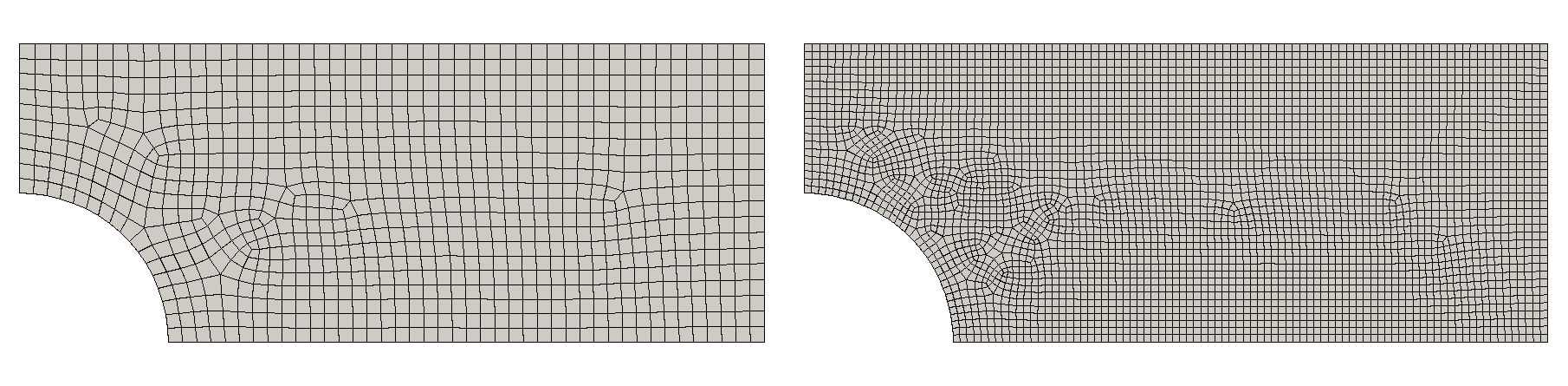
Fig. 3 Plate with hole meshes.
The elements used for all simulations are uniform gradient hexahedron elements. Two meshes, mesh1 and mesh2, are considered (Fig. 3). mesh1 has a plate half-thickness t=0.05; mesh2 has t=0.025 and approximately half the element size of mesh1. Both meshes have one element through the thickness direction, so the element size differs between the two meshes to maintain the same element aspect ratio. The plate thickness is decreased from mesh1 to mesh2 to evaluate the affect of thickness on the out-of-plane stresses.
Feature Tested
Plane stress/strain boundary conditions.
Results and Discussion
As can be seen in Fig. 4, the plane strain condition is represented in both meshes by prescribing zero displacements in the out-of-plane direction (the z-direction). As can be seen in Fig. 5, the accuracy of the plane stress increases as the plate thickness decreases, as expected. Each of the plane stress boundary conditions in Table 1 show a similar level of accuracy. For these plane stress approximations, the maximum absolute value of the out-of-plane stress is three orders of magnitude less than the applied traction, and negligible a sufficient distance from the hole.
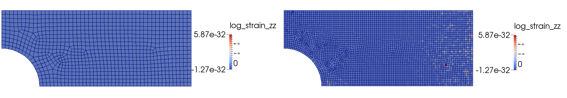
Fig. 4 Plate with hole results for zero z-displacement prescribed on positive-z face.
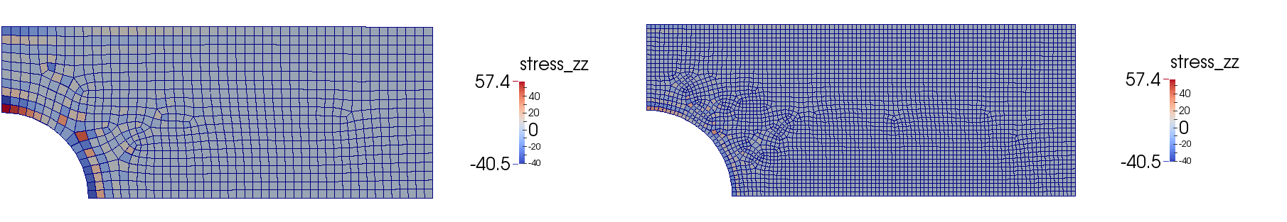
Fig. 5 Plate with hole results for zero pressure prescribed on positive-z face.