Bolt Preload
Product: Sierra/SolidMechanics - Explicit Analysis
Problem Description
This example demonstrates the process of preloading a bolt in five manners: t hermal strain, artificial strain, the preload command, prescribed displacement, and a spring. In reality a bolt and nut could be used to clamp components of a joint by the application of a preload. This could be applied through the shaft by a bolt head and nut, thereby bounding respective surfaces together. For simplicity, this example implements a single loading block, a bolt head, and a theoretical nut of matching dimensions. The loading block for these test cases can be seen in Fig. 6 and the assembly diagrams can be seen in Fig. 7.
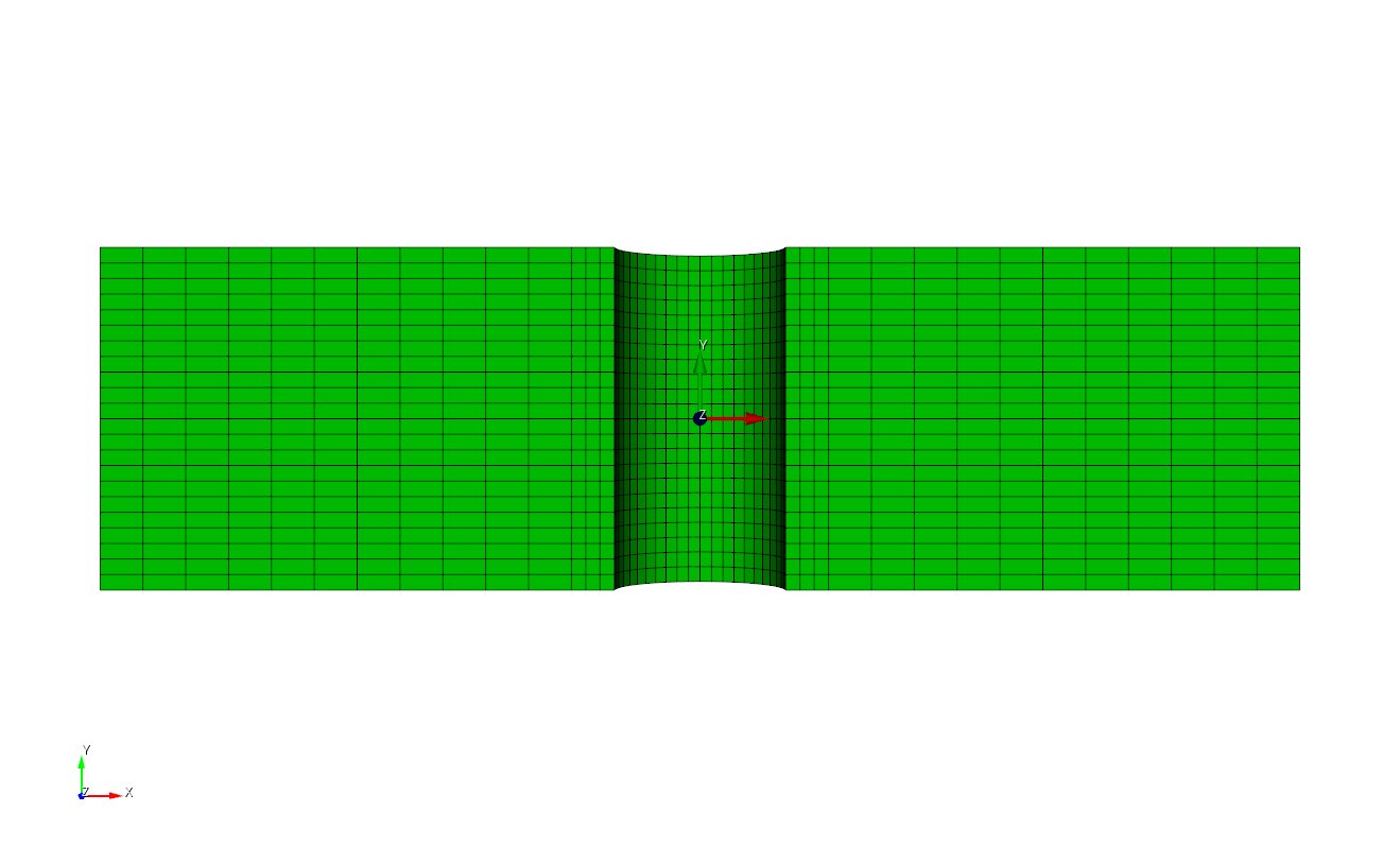
Fig. 6 Loading Block for the Five Preloading Cases
 Thermal/Artificial Strain and Preload Command
 Prescribed Displacement (mesh overlap)
 Spring
Fig. 7 Bolt Assembly Diagram for the Five Preloading Cases
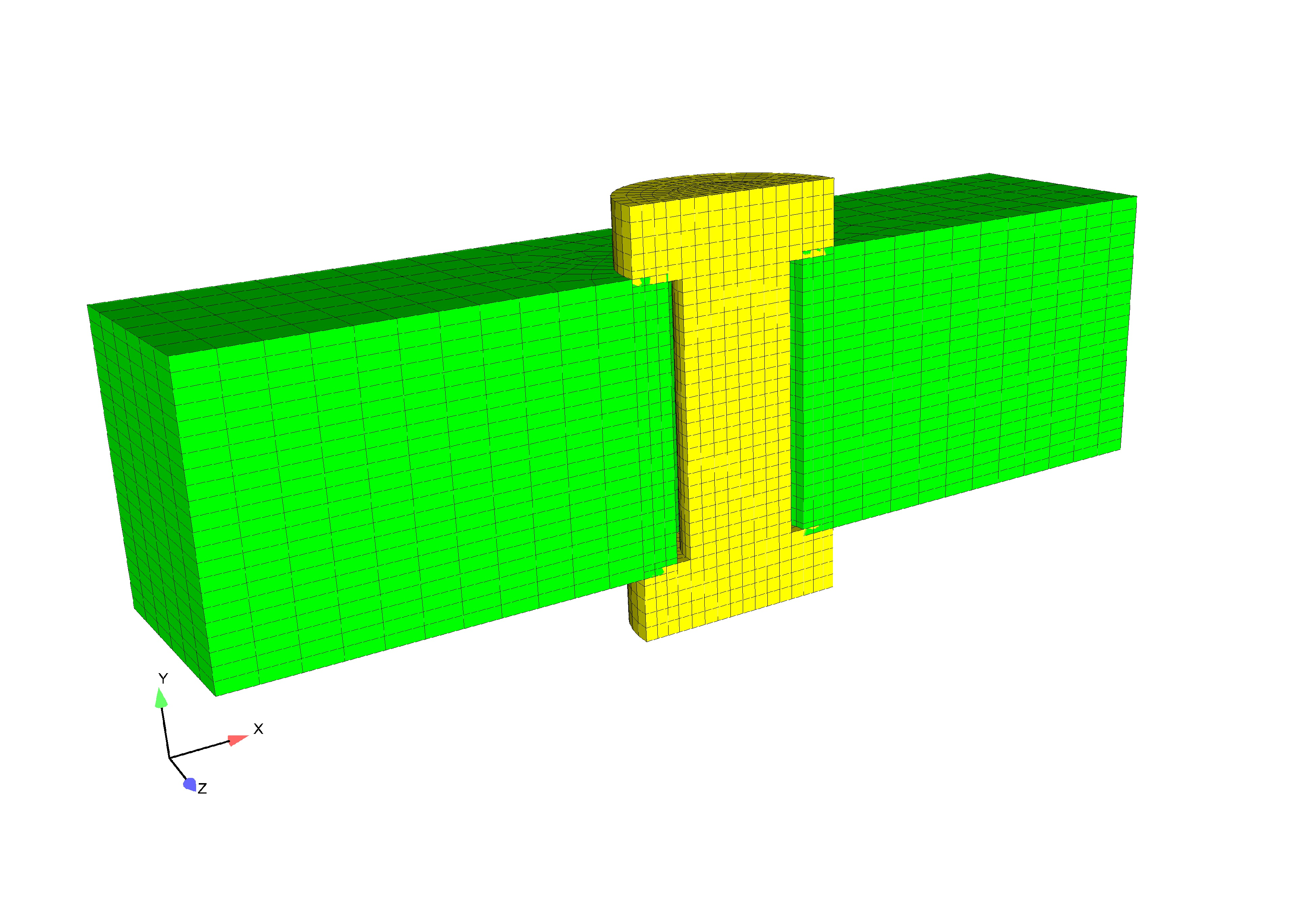
In the first case, a preload is simulated through a thermal strain on a bolt. The entire bolt is cooled to -10 Kelvin at which point an orthotropic thermal engineering strain of 0.05 is applied to the bolted joint along the longitudinal axial direction of the bolt. Both ends of the bolt flanges lay flush with the joint. The isometric view of this preloading can be seen in Fig. 8.
In the second case, a preload analysis is simulated by defining an artificial strain to a bolt. The bolt is prescribed an anisotropic strain aligned with the global X, Y and Z axes. Both ends of the bolt flanges lay flush with the joint. The isometric view of this preloading case is identical to that of the thermal case and can be seen in Fig. 8.
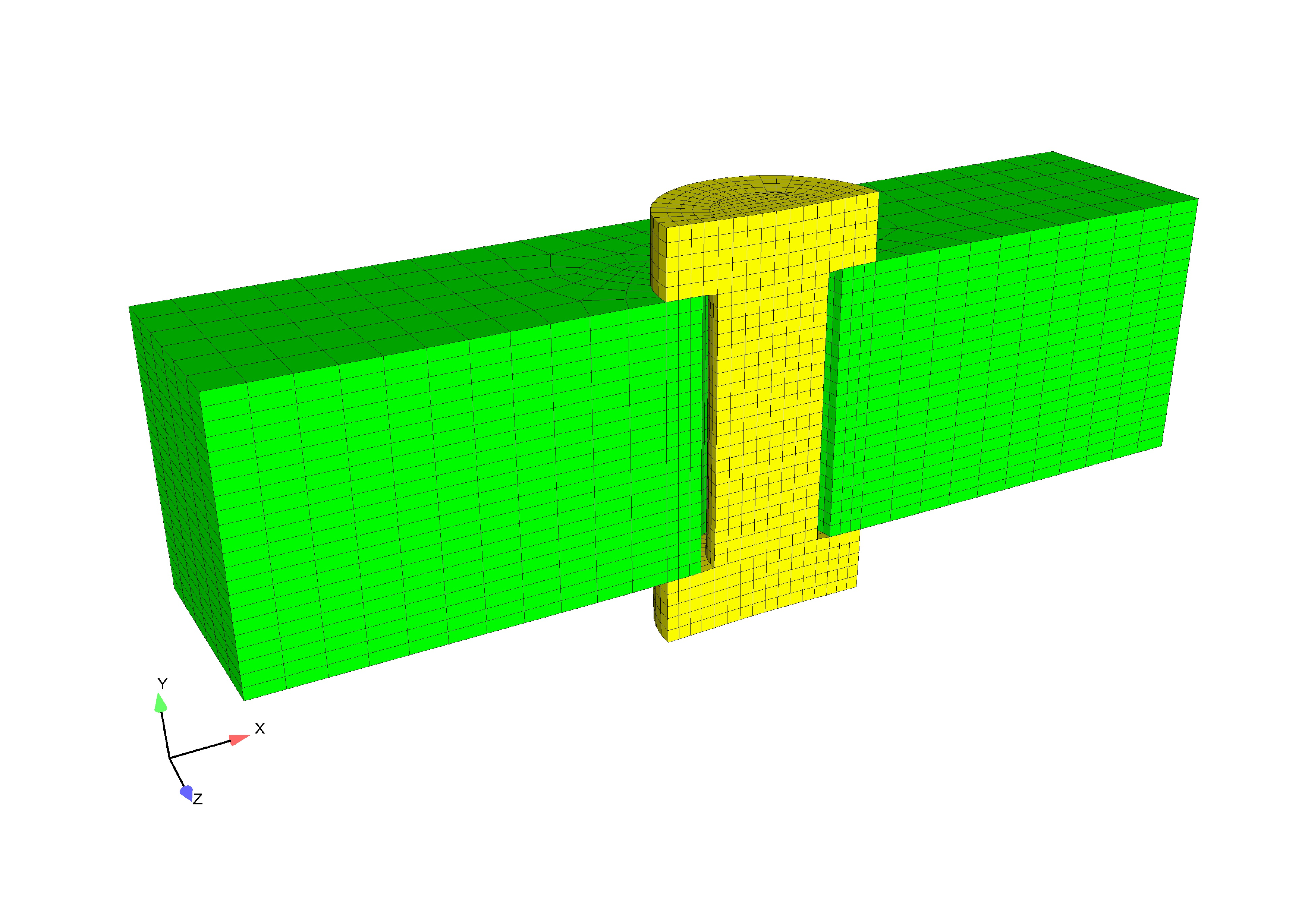
Fig. 8 Preload test case: Thermal and Artificial Strain
In the third case, the preload is achieved via the begin preload command.
The preload command still calls the artificial strain under the hood, but it
allows the user a much simpler interface for specifying the preload.
The bolt is preloaded to a maximum von_mises value of 1.0e10 in the y direction.
The simple syntax for defining this preload is as follows:
begin preload
  preload bolt block_2 to target max_von_mises_bolt2 = 1.0e10 in direction my_y
end
Note that if you are preload a simple geometry such as a cylinder or a disk, the direction need not be specified. The max_von_mises_bolt2 is computed via the following user output block:
begin user output
  block = block_2
  compute global max_von_mises_bolt2 as max of element von_mises
  compute at every step
end
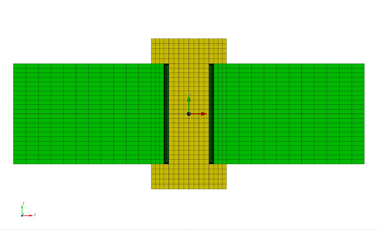
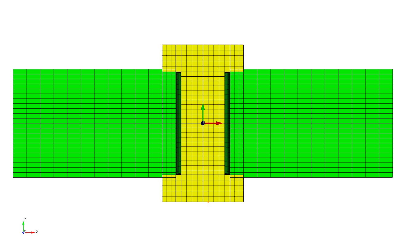
In the fourth case, a prescribed displacement is applied to a bolt to simulate preload. The model is set-up in a ‘stress free’ condition with both ends of the bolt overlapping the joint by approximately half an element’s length. With contact turned off on the bottom and top surfaces, the bolt is pulled into place using a prescribed displacement. After the bolt flanges are displaced enough to lay flush with the joint, contact on the top and bottom surfaces is turned on and the artificial force is released. The isometric view of this preloading case can be seen in Fig. 9.
 Prescribed Displacement
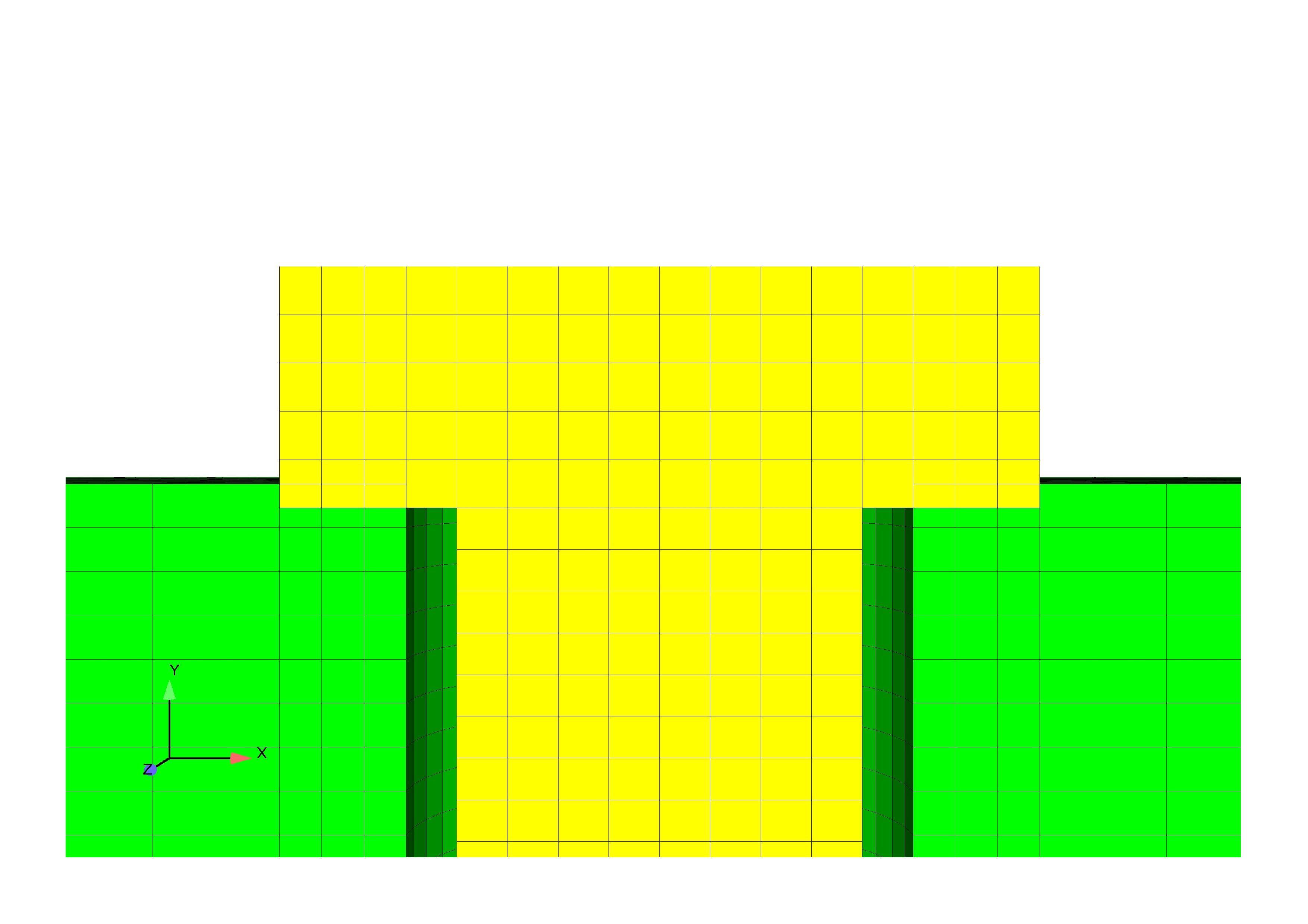 Close Up Of Mesh Overlap
Fig. 9 Preload test case: Prescribed
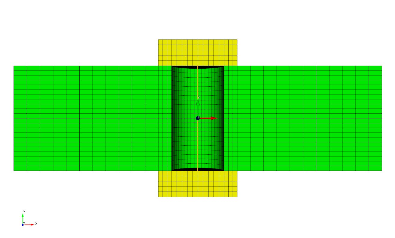
In the fifth case, a preload analysis is simulated by defining a spring section on a bolt. In this analysis the middle section of a bolt is replaced with a preloaded two node spring of equivalent cross sectional area to the thermal and prescribed displacement cases. The spring section can be adjusted to provided the desired preload in the bolt material. Both ends of the bolt flanges lay flush with the joint. The isometric view of this preloading case can be seen in Fig. 10.
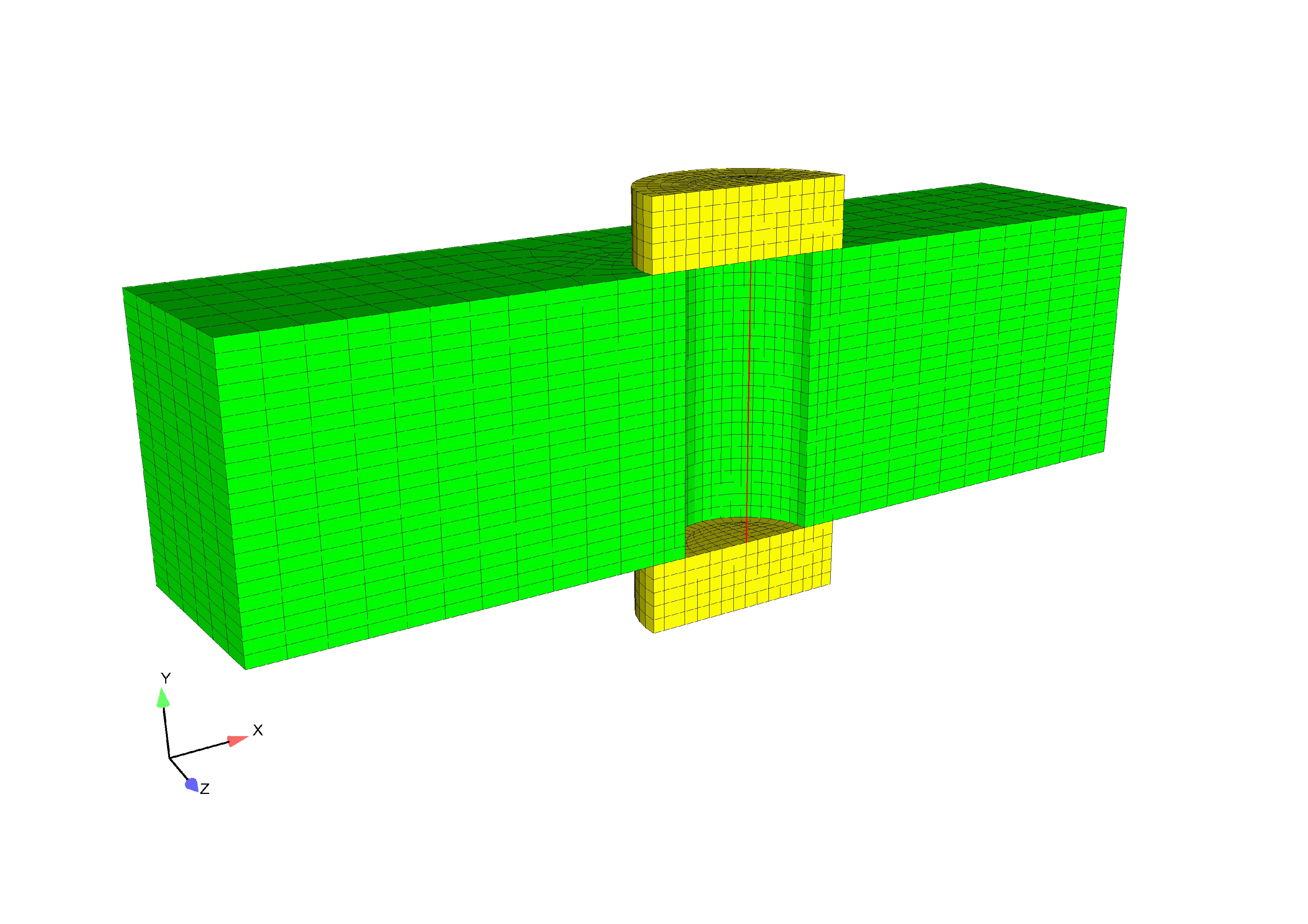
Fig. 10 Preload test case: Spring
Loading and Boundary Conditions
In the prescribed displacement, preload, thermal strain, and artificial strain cases a fixed displacement is set on the cross sectional front face of the bolt in addition to the front face of the joint block. This allows for a symmetric model. The upper and lower outer portion of bolt flanges are fixed in all directions. The side A-side B contact syntax is defined between the upper and lower inner flanges with the block.
The FETI equation solver uses a damping coefficient of 0.0001 in the five load cases.
Material Model
In the thermal preload case, an orthotropic thermal strain field is applied in the material specification command block; the thermal strain is a general material property and not part of a constitutive model such as Elasticity. It is required that the orthotropic thermal strain in the X, Y, and Z be placed inside of material the command block. This example demonstrates thermal strain along the y-axis, setting the change in strain with decreasing temperature to zero along the x and z axis.
An anisotropic strain is applied in the artificial strain bolt preload condition. If desired, an isotropic thermal or artificial strain can be applied in the material specification command block. This would demonstrate equal physical properties along all axes.
The following material properties were used during analysis:
Metric units are used |
|---|
Displacement: meters |
Mass: kilograms |
Time: seconds |
Force: \(kgm/s^2\) |
Temperature: Kelvin |
Bolt Preload |
||
|---|---|---|
Young’s Modulus: Block and Bolt |
E |
\(200\times10^9\) |
Poisson’s Ratio |
\(\nu\) |
\(0.29\) |
Density |
\(\rho\) |
\(7.89\times10^3\) |
Finite Element Model
For all five cases, the bolt and outer block implement a hex mesh, while the spring was created using a bar. Various webcuts are defined to obtain precise nodeset and block specifications across the different load cases.
Results and Discussion
Results obtained from the thermal, spring, prescribed displacement, and artificial strain bolt preload cases were calculated using input to allow similar analytical solutions. The \(\sigma_{yy}\), \(\sigma_{xx}\), and \(\sigma_{xy}\) stresses for the five loading conditions can be seen in Fig. 11, Fig. 12, and Fig. 13. The \(\sigma_{yy}\) stress is aligned with the bolt axis.
In addition, mesh generation in the five cases were created to mimic geometries, yet also satisfy the appropriate loading conditions. For example, the central cross section of the thermal bolt was replaced with a two-noded bar and a representative rigid body cross sectional area in the spring case.
Preload |
Very straightforward set up and makes preloading many different |
bolts an easy task. |
|
Thermal |
Well used for problems that are insensitive to temperature.newline Straightforward set up. |
Artificial |
Well used for problems that are sensitive to temperature. Straightforward set up. |
Prescribed |
A higher degree of setup difficulty, but most realistic if mesh overlap is present. |
Spring |
If a problem force is well known, it can be put directly into spring. Moderate set up. |
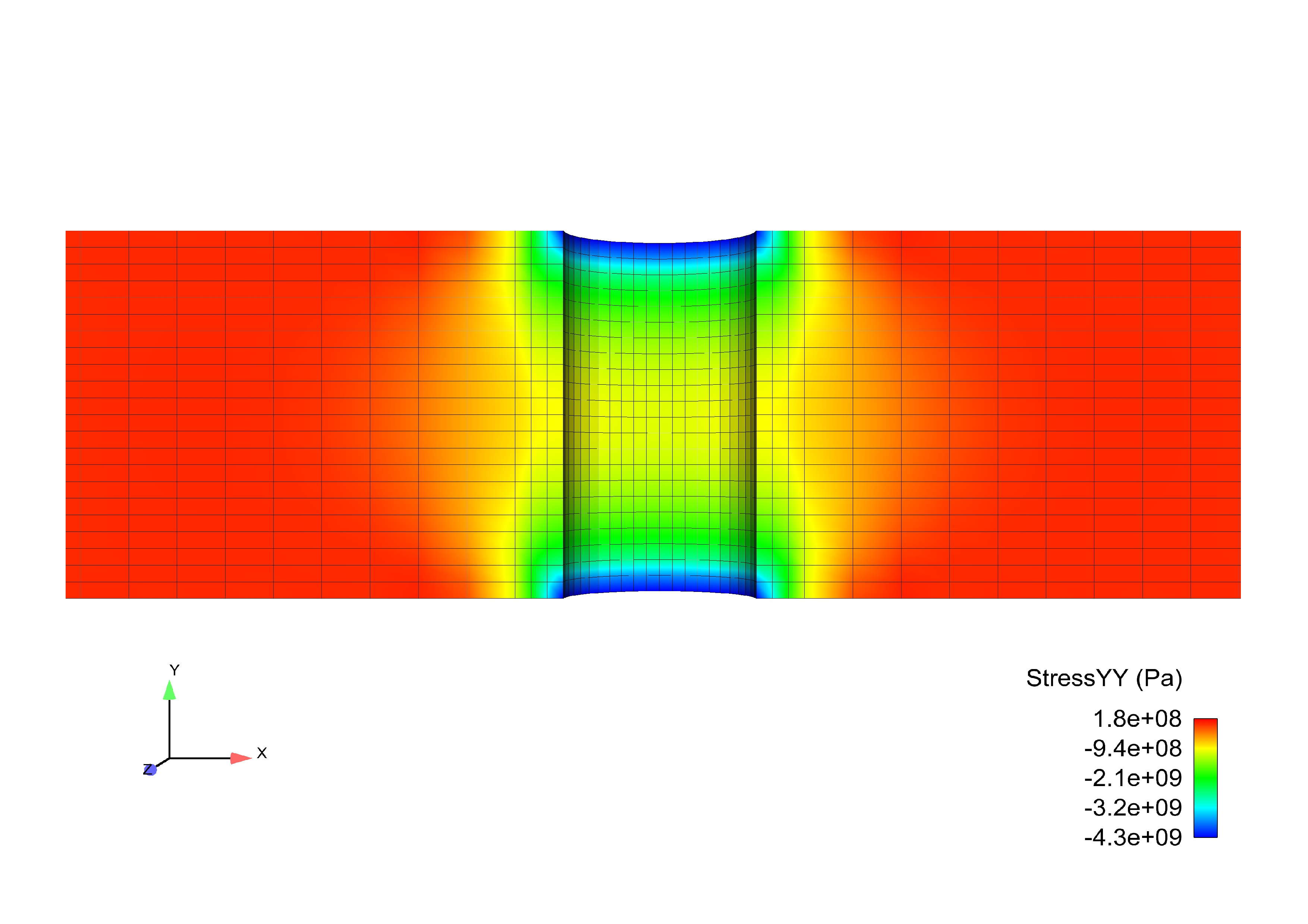
Fig. 11 Bolt Preload: \(\sigma_{yy}\)
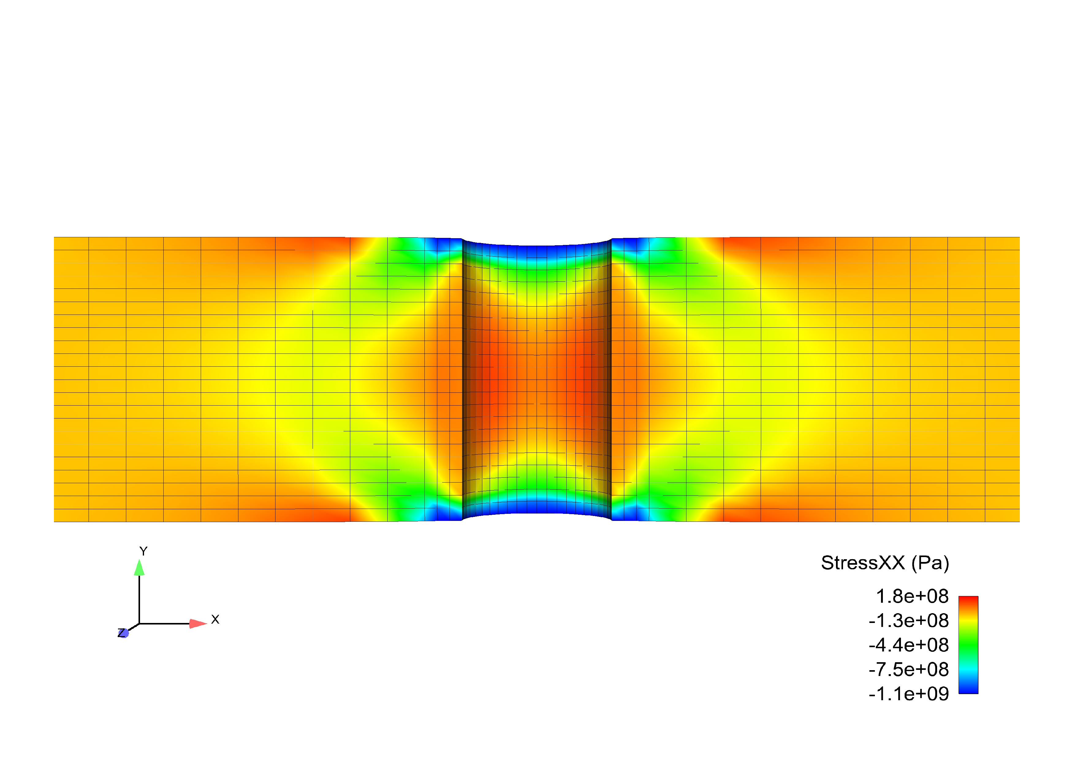
Fig. 12 Bolt Preload: \(\sigma_{xx}\)
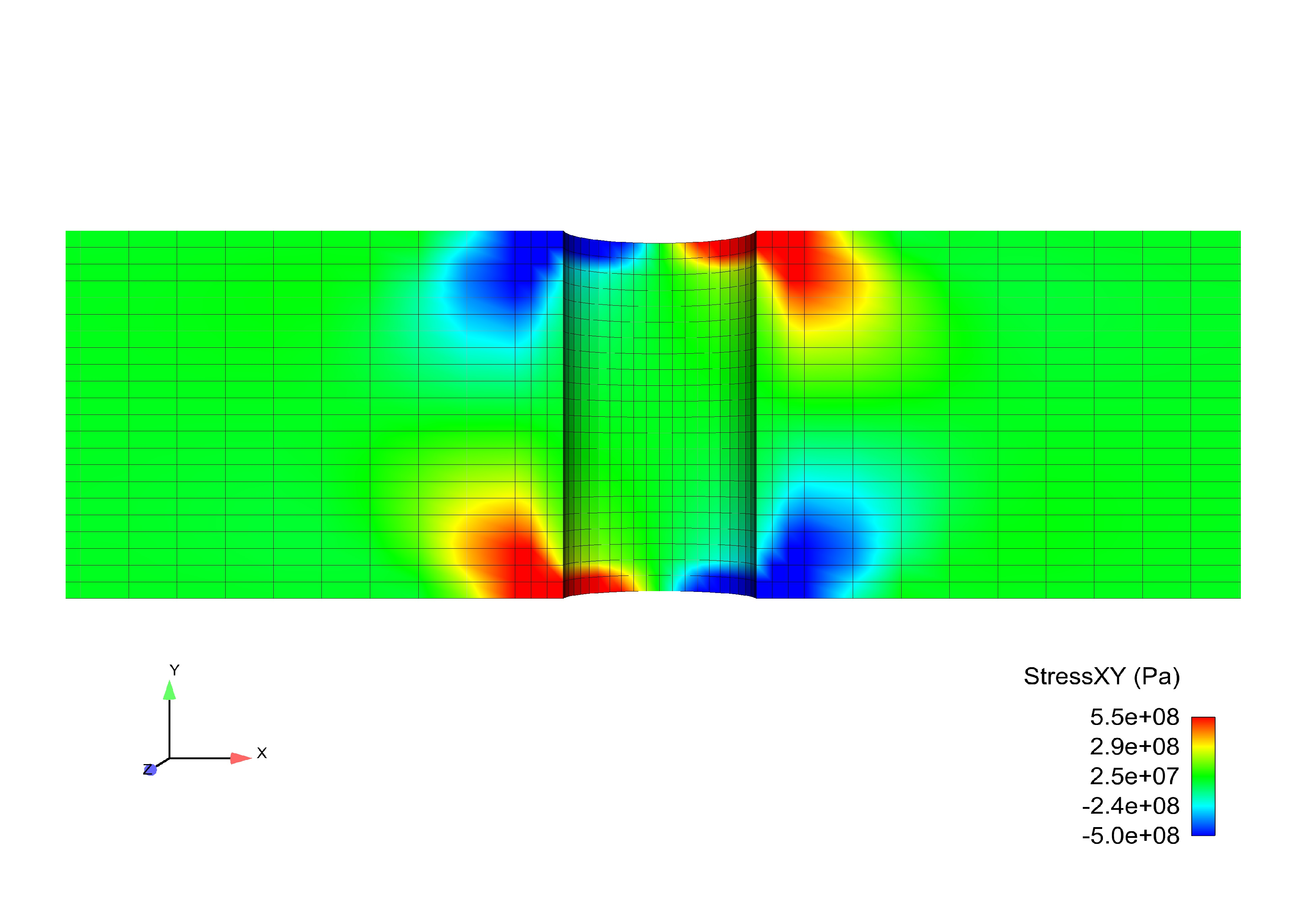
Fig. 13 Bolt Preload: \(\sigma_{xy}\)