Frame Indifference
Problem Description
The Frame Indifference Test requires the constitutive model to be self-consistent under superimposed rigid rotation and translations. This feature is tested through applying a uniaxial artificial strain to a single cube-shaped element, followed by an arbitrary rotation.
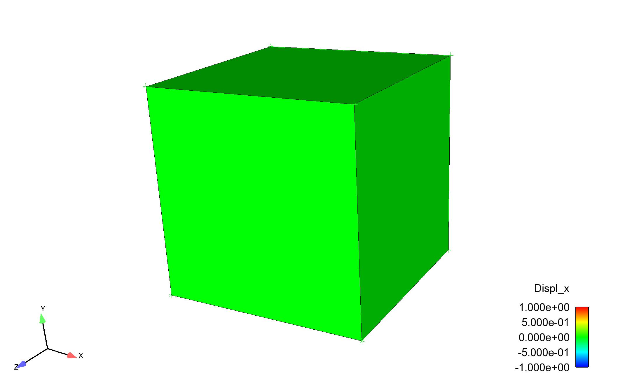
Fig. 25 Initial Configuration
Loading and Boundary Conditions
Initially, the block is given an artificial strain in the positive X direction. During the application of artificial strain all nodes are fixed from moving in the X, Y, and Z directions, which creates an internal element stress. Once the artificial strain reaches its maximum value, the block rotates 90 \(^\circ\) about the Z axis. Rotation is achieved with a prescribed velocity function using a cylindrical axis; the fixed displacement boundary condition remains on all nodes during rotation. This prevents the block from deforming, but not from rotating. Fig. 26 shows the block halfway through its rotation and Fig. 27 shows the complete 90 \(^\circ\) rotation.
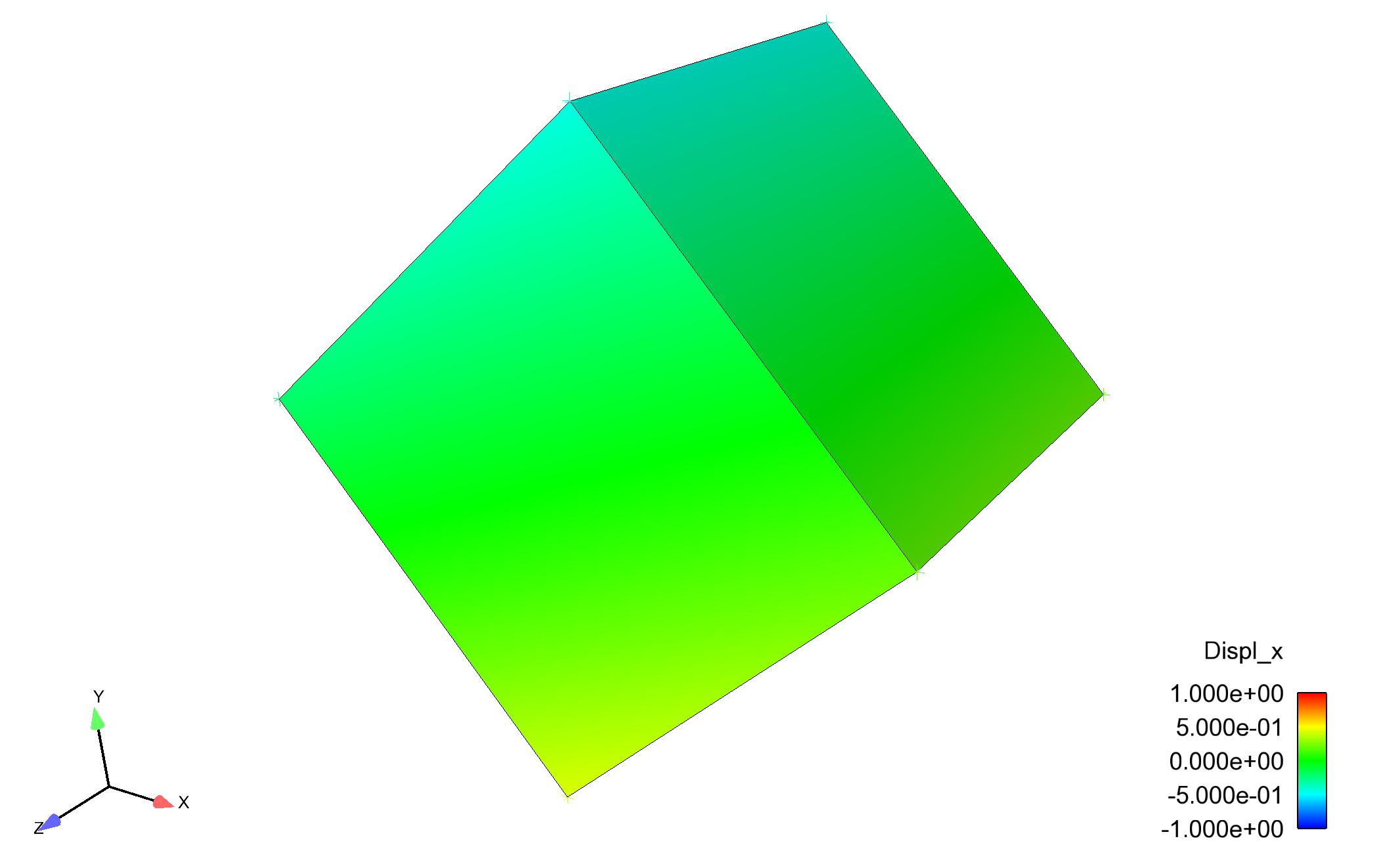
Fig. 26 Midpoint of Block Rotation
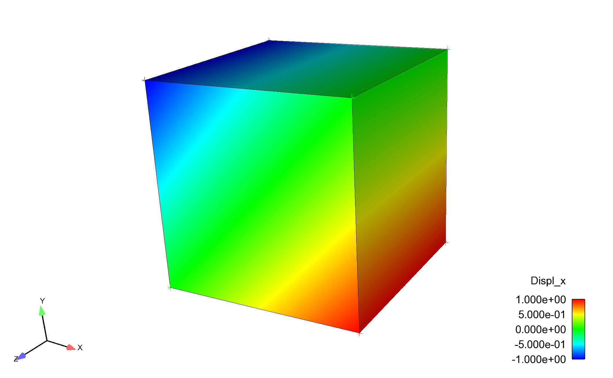
Fig. 27 Deformed Element after 90 \(^\circ\) rotation about the z-axis
Material Model
This test contains an elastic-plastic model, and is given material properties similar to steel.
The following material properties were used during analysis:
Metric units are used |
|---|
Displacement: meters |
Mass: kilograms |
Time: seconds |
Force: \(kgm/s^2\) |
Temperature: Kelvin |
Material Properties |
||
|---|---|---|
Young’s Modulus |
E |
\(200\times10^9\) |
Poisson’s Ratio |
\(\nu\) |
0.33 |
Density |
\(\rho\) |
\(7.871\times10^3\) |
Yield Stress |
\(\sigma _{yield}\) |
\(2.76\times10^8\) |
Finite Element Model
This test contains a single hex element.
Feature Tested
The primary features tested in this problem are the artificial strain and cylindrical rotation features, while verifying frame indifference.
Results and Discussion
This problem, implementing superimposed rotations applied to the spatial domain, provides consistent results to the non-rotating uniaxial strain problem. Accordingly, in-plane principle stress components are accounted for during the rotation portion of the analysis. This verification test was adopted from, “Verification tests in solid mechanics: Engineering With Computers Volume:29 Number:4” (K. Kamojjala et al. 2013).
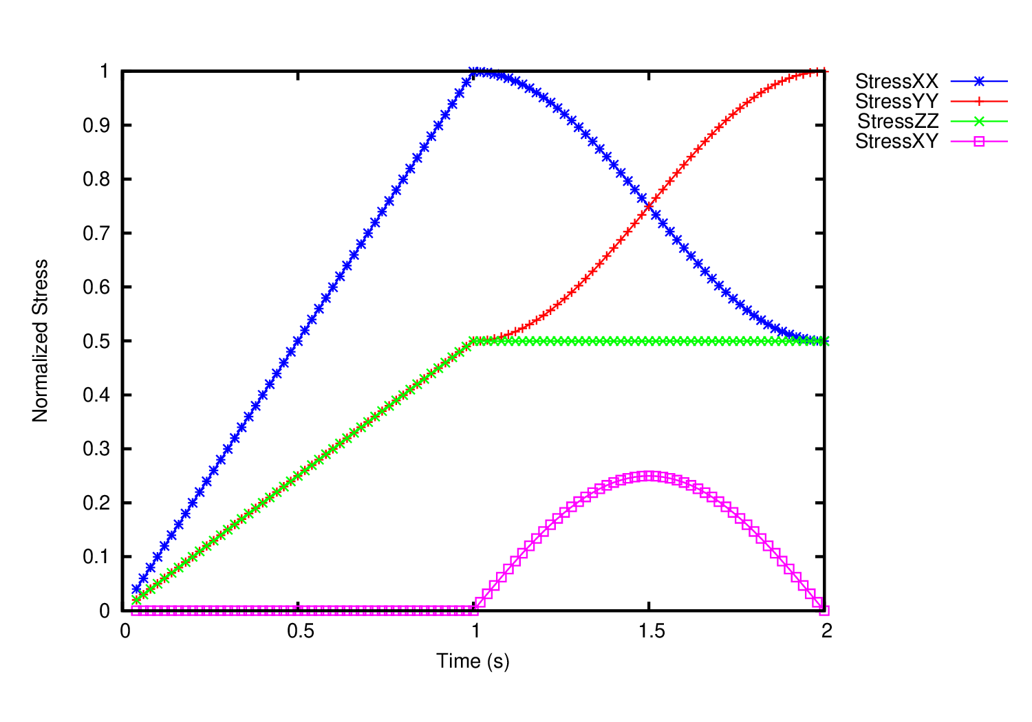
Fig. 28 Normalized Stress Plot