Cohesive Zones
Problem Description
This example demonstrates creating and using cohesive elements in Sierra/SM. Cohesive elements can either be created in the input mesh, as a contact friction model, or on-the-fly using XFEM.
Finite Element Model
Meshed Cohesive Zone
In order to create a mesh that has a cohesive zone with a starting volume of zero there are a few steps in creating the mesh. The first step is to create a mesh that has the two blocks that will be connected by the cohesive zone. It is necessary to leave a small gap in between the two blocks in order to insert a block in between them which will represent the cohesive zone. A volume will then need to be created between the two blocks, for example, using Cubit, via the command
create volume loft surface
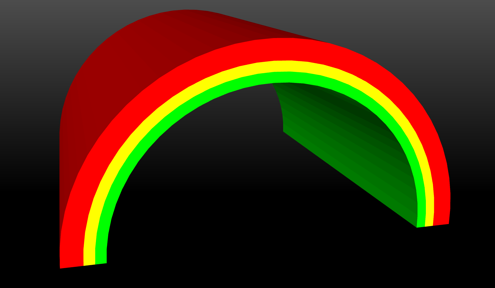
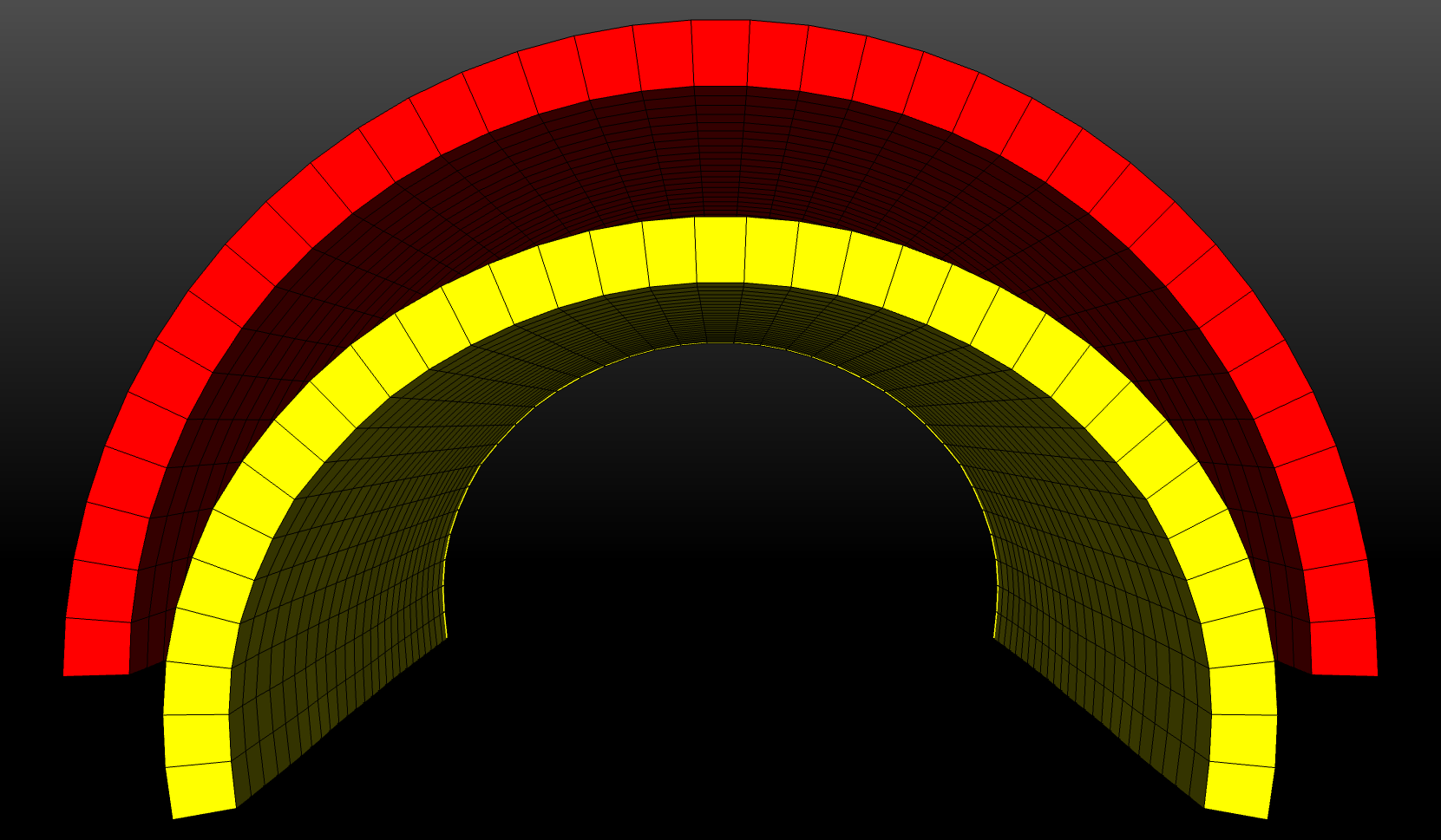
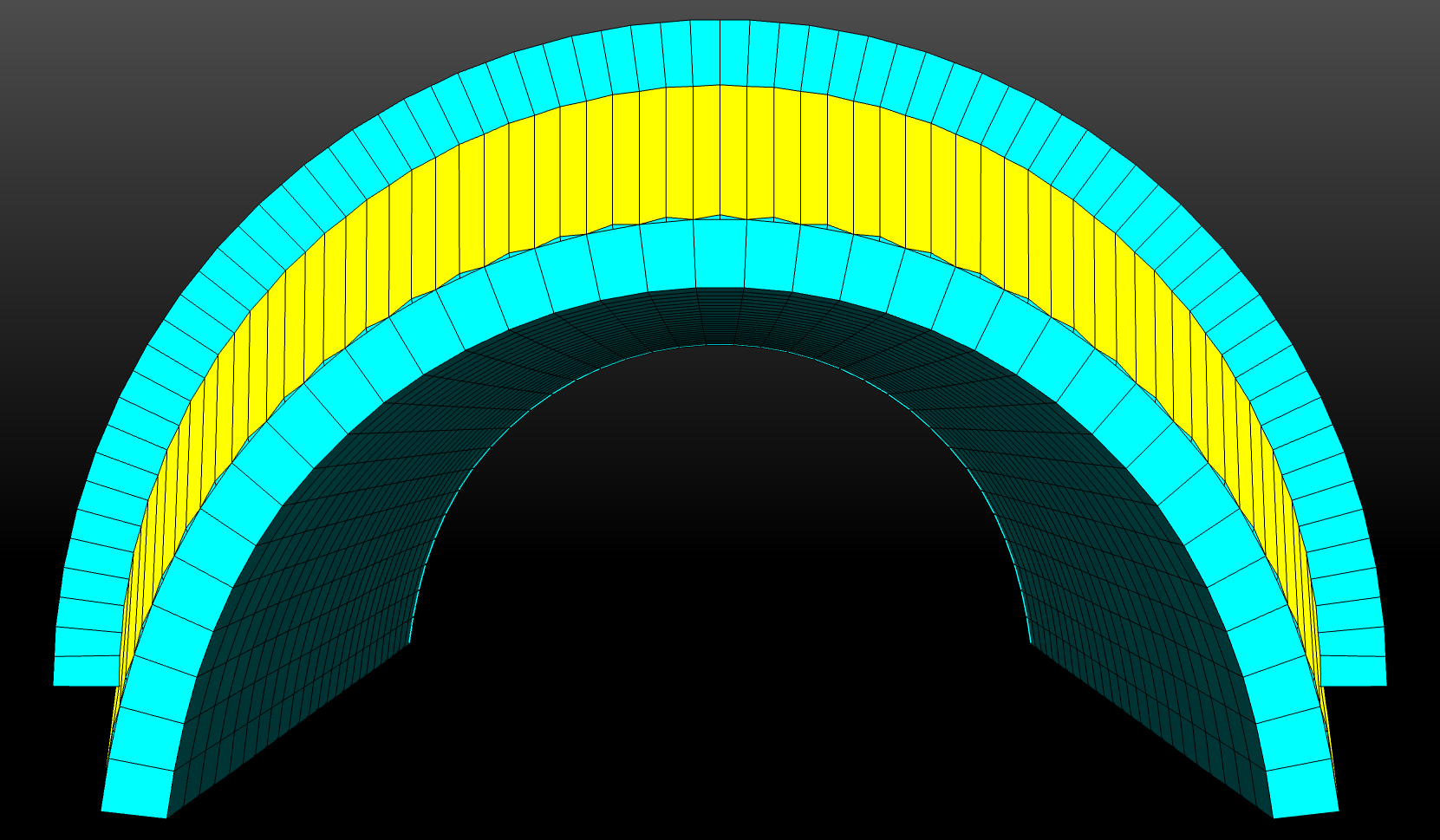
Fig. 29 Mesh with original cohesive zone
In Fig. 29, the red and green blocks are merged with
the yellow block, which represents the cohesive zone.
In order to remove the volume of the cohesive zone block the coordinates of
the two surfaces connected to the yellow will need to be known.
In this example the green block will be stretched until it is touching the
red block, which will add the volume of the yellow block to the green block.
After the coordinates have been found, the SEACAS tool exotxt may be
used to convert the created mesh file to plain text.
All of the coordinates on the surface of the green block are should then be
changed in the plain text file to the coordinates on the red block.
Once all of the coordinates have been altered, txtexo
may be used to create a new mesh, shown in Figure Fig. 30,
in which the yellow block now has zero volume.
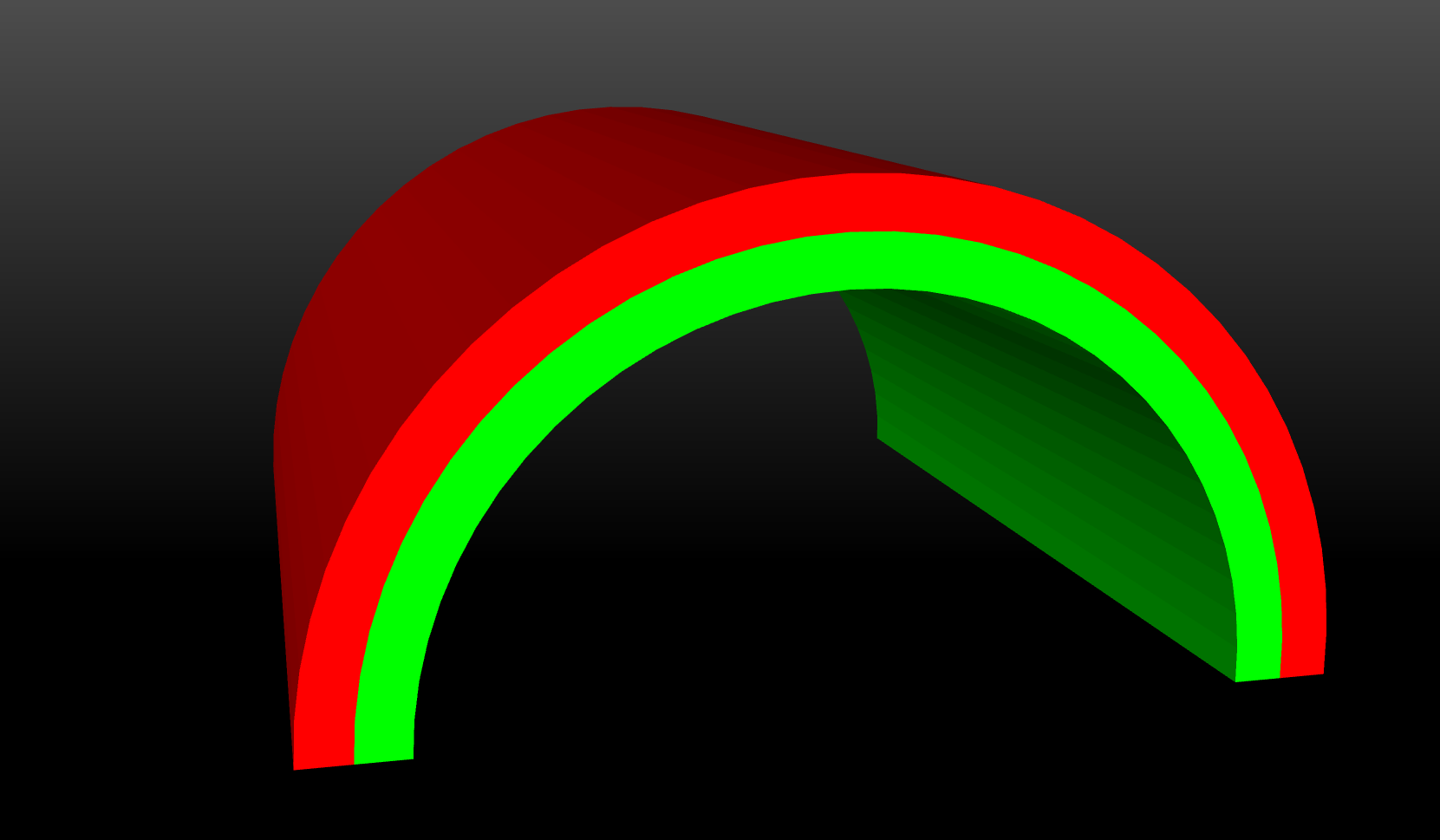
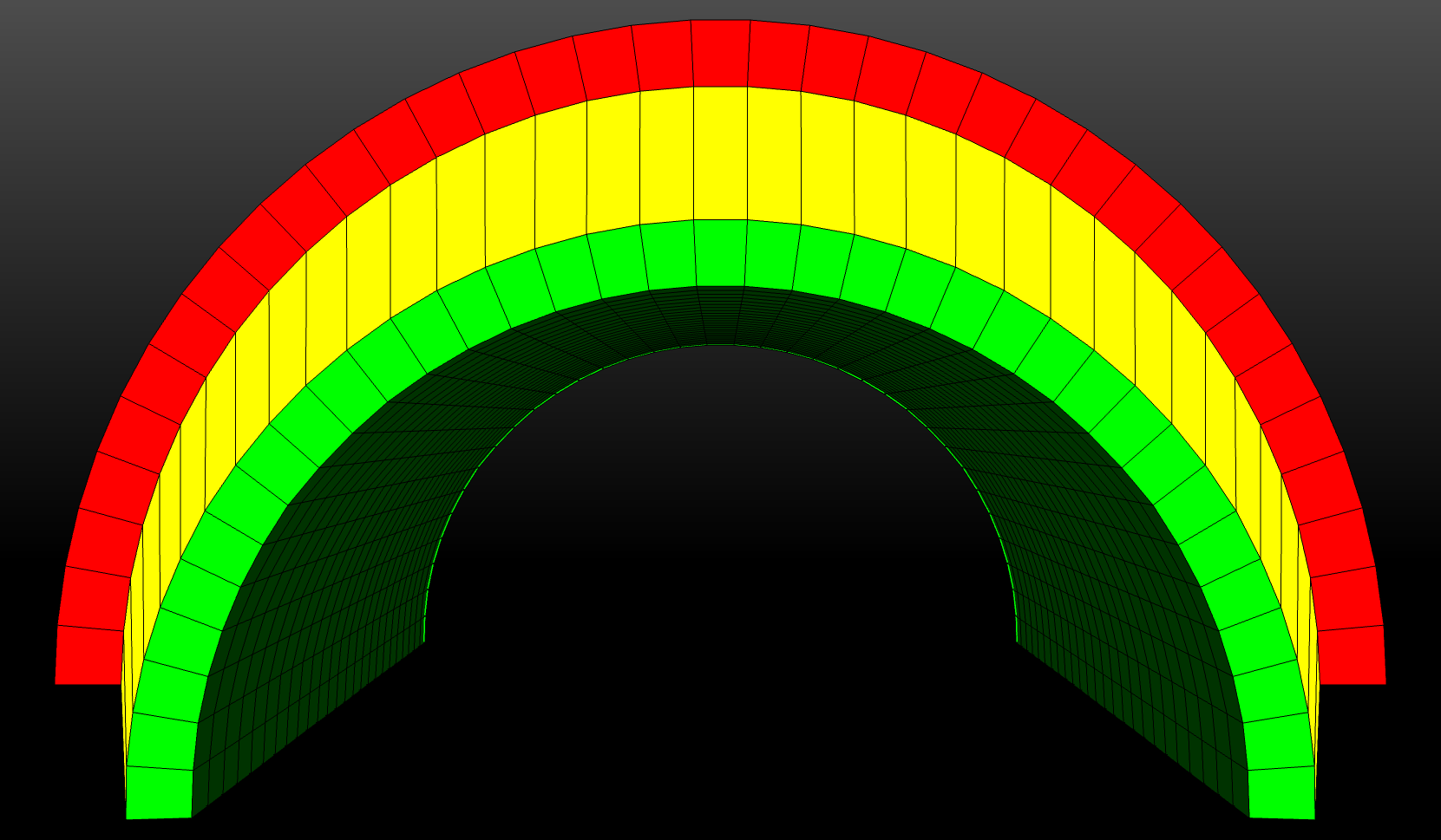
Fig. 30 Mesh with new cohesive zone
Contact Cohesive Zone
In order to create the same mesh as the previous example the same outer half-cylinder needs to be created, along with another half-cylinder that takes the place of the two inner cylinders. The volumes will then be imprinted and merged so that the mesh matches the previous mesh and the results can then be compared. After the mesh is created it is necessary to unmerge the two volumes (so that they are not sharing nodes) and save them to different blocks on the output mesh.
XFEM Cohesive Zone
The XFEM mesh follows many of the same steps that the contact cohesive mesh used, for example, creating the same two half-cylinders and meshing them. After meshing the two volumes, a sideset must be placed on the connecting surface. This sideset will be used by XFEM to cut the two cylinders apart. The blocks will then be saved to a single block on the output mesh.
Boundary Conditions
For simplicity in all three tests the two half-cylinders are stretched apart using prescribed and fixed displacement boundary conditions. The bottom surface of the bottom plate has a prescribed downward displacement, while the top surface of the top plate is fixed. For the contact cohesive zone problem it is additionally required to add a contact definition with a cohesive zone friction model.
begin cohesive zone model cohesive_zone
  critical normal gap = 0.05
  critical tangential gap = 0.05
  traction displacement function = spring_restore
  traction displacement scale factor = 2.5E+04
end cohesive zone model cohesive_zone
This model will not be able to use the same criteria as the other two examples because it will use the values from this friction model instead of the Tvergaard–Hutchinson model. The XFEM problem also requires an XFEM command block as follows:
initial cut with [SIDESET|STL] <string>file_or_surface_name
  REMOVE {INTERIOR|EXTERIOR|NOTHING(NOTHING)}
initial surface cohesive = true
cohesive section = <string>cohesive_section_name
cohesive material = <string>cohesive_material_name
cohesive model = <string>cohesive_model_name
These commands will cut the one block into the two different half-cylinders and add a cohesive zone between the two blocks.
Material Model
In this example two different material models were used: elastic and tvergaard_hutchinson.
begin parameters for model elastic
  youngs modulus  = 30.e5
  poissons ratio  = 0.3
end parameters for model elastic
begin parameters for model tvergaard_hutchinson
  lambda_1 = 0.5
  lambda_2 = 0.5
  normal length scale = 0.1
  tangential length scale = 0.1
  peak traction = 50.0e3
  penetration stiffness multiplier = 1.0
  use elastic unloading = no
end parameters for model tvergaard_hutchinson
The elastic material model was used for the two half-cylinders, while the Tvergaard–Hutchinson cohesive zone model was used in both the meshed and XFEM examples.
Metric units are used |
|---|
Displacement: meters |
Mass: kilograms |
Time: seconds |
Force: newtons |
Temperature: Kelvin |
Results and Discussion
 Contact
 Mesh Cohesive Zone
 Xfem
Xfem
Fig. 31 Results of cohesive zone test
When comparing the three different results at the final timestep, there is a visual difference between all three methods. The contact method is different because of the different cohesive zone definition, but the meshed and XFEM methods are also different. When XFEM cuts the mesh, it is not cutting perfectly along the mesh edge, which modifies the mesh slightly. The bottom cylinder has an extra layer of small elements, while the element in the top cylinder is cut in half. The differences in simulation run times among the three cohesive zone modeling methods are also shown in Table 8.
Method |
Time (s) |
|---|---|
Meshed |
0.7627 |
Contact |
2.7654 |
XFEM |
65.1444 |
The explicitly meshed modeling approach is the quickest while the XFEM is the slowest. The XFEM- and contact-based algorithms incur a significant overhead in computational cost relative to the meshed cohesive zone.
Each method has advantages and disadvantages when considering creating a mesh and running simulation with cohesive zones. The meshed method can be very difficult to mesh; however, it has the lowest computational cost. The contact method allows for relative ease in mesh creation and does not incur a very large increase in simulation run time, but cohesive zone material models are not supported in this approach. XFEM is by far the simplest method to mesh, but it is very expensive in terms of simulation run time.