Overlap Removal Methods
Problem Description
This example demonstrates the process of removing overlap from two rings using two different methods: overlap removal and artificial stain coupled with general contact.
In the first case, the two rings have a small overlap due to the inner ring being slightly larger than the inner radius of the outer ring. This overlap removal block will be placed directly into the contact block. In Fig. 20 the left side is showing the model before the overlap is removed while the right is showing the resulting model after the removal.
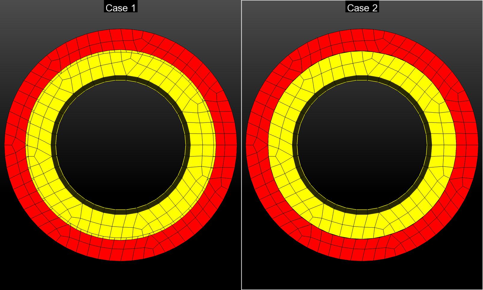
Fig. 20 Small overlap and results after overlap removal
In the second case, a large overlap will be removed from the rings using an artificial strain in the radial direction for the first time period as shown in Fig. 21. Then contact is activated and the artificial strain is removed as you can see on the right side of the plot in Fig. 21. In Fig. 22 the left side is showing the model before anything is done and the right is showing how the model will look after the removal method.
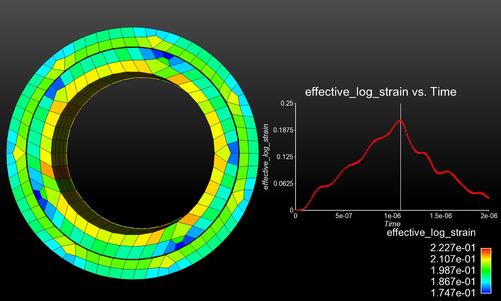
Fig. 21 Rings under strain with strain vs time plot
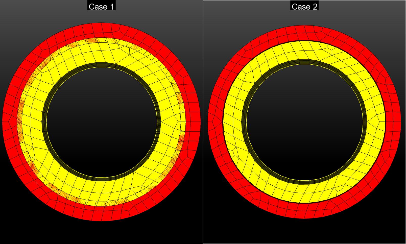
Fig. 22 Large overlap and results after overlap removal method
Boundary Conditions
No boundary conditions where applied to these models.
Material Model
In both of these cases an elastic orthotropic material model with isotropic properties was used. The elastic orthotropic model allows specification of a cylindrical coordinate system, so that strain can be applied in the radial direction.
The following material properties were used during analysis:
Metric units are used |
|---|
Displacement: meters |
Mass: kilograms |
Time: seconds |
Force: \(kgm/s^2\) |
Temperature: Kelvin |
Overlapping Rings |
||
|---|---|---|
Young’s Modulus: Block and Bolt |
E |
\(64\times10^9\) |
Poisson’s Ratio |
\(\nu\) |
0.20 |
Density |
\(\rho\) |
0.5 |
Finite Element Model
For the small overlap case the inside ring was made to have an outside radius of 0.205 while the outer ring has an inner radius of 0.20. For the larger overlap the case the inside ring has an outer radius of 0.2125 while the outer ring has the same inner radius. Both of these cases were created using a simple hex mesh.
Results and Discussion
Results obtained from the overlap removal case showed that no stress or strain was applied to the system in order to remove the overlap; however, this method could handle a larger overlap than 50 percent of the smallest element size. In the case where strain was applied larger amounts of overlap could be removed, however a resulting stress and strain value is added to the system causing the rings to change from their original configurations. In Fig. 23 the max principle stress of the resulting model is zero, while in Fig. 24 both of the rings are experiencing large values of stress.
Overlap Removal |
Simple to use for small amounts of overlap. Straightforward set up. |
Artificial Strain and General contact |
Works for large overlap but leaves a stress and deformation of original setup. Moderate set up. |
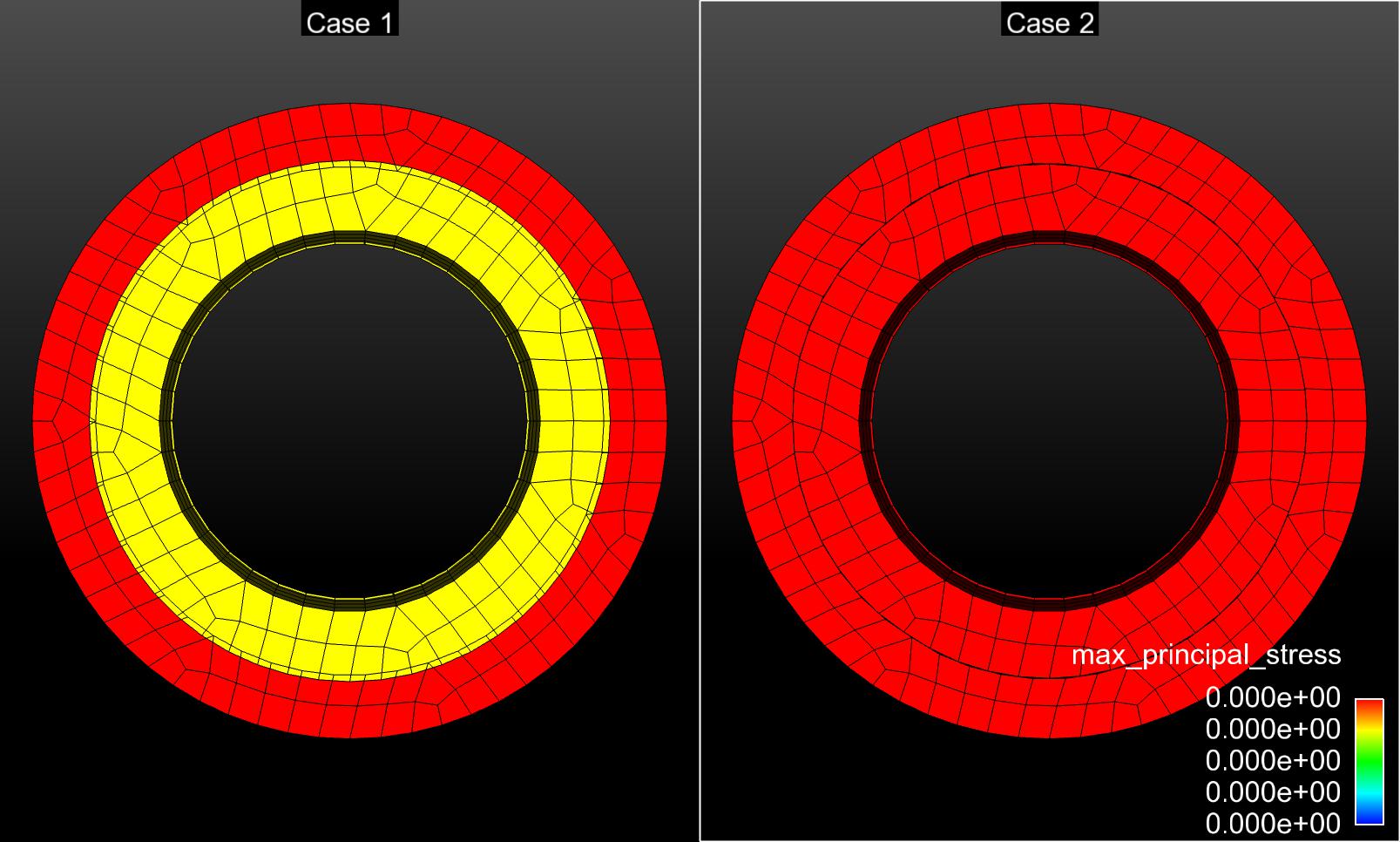
Fig. 23 Stresses experienced after overlap removal
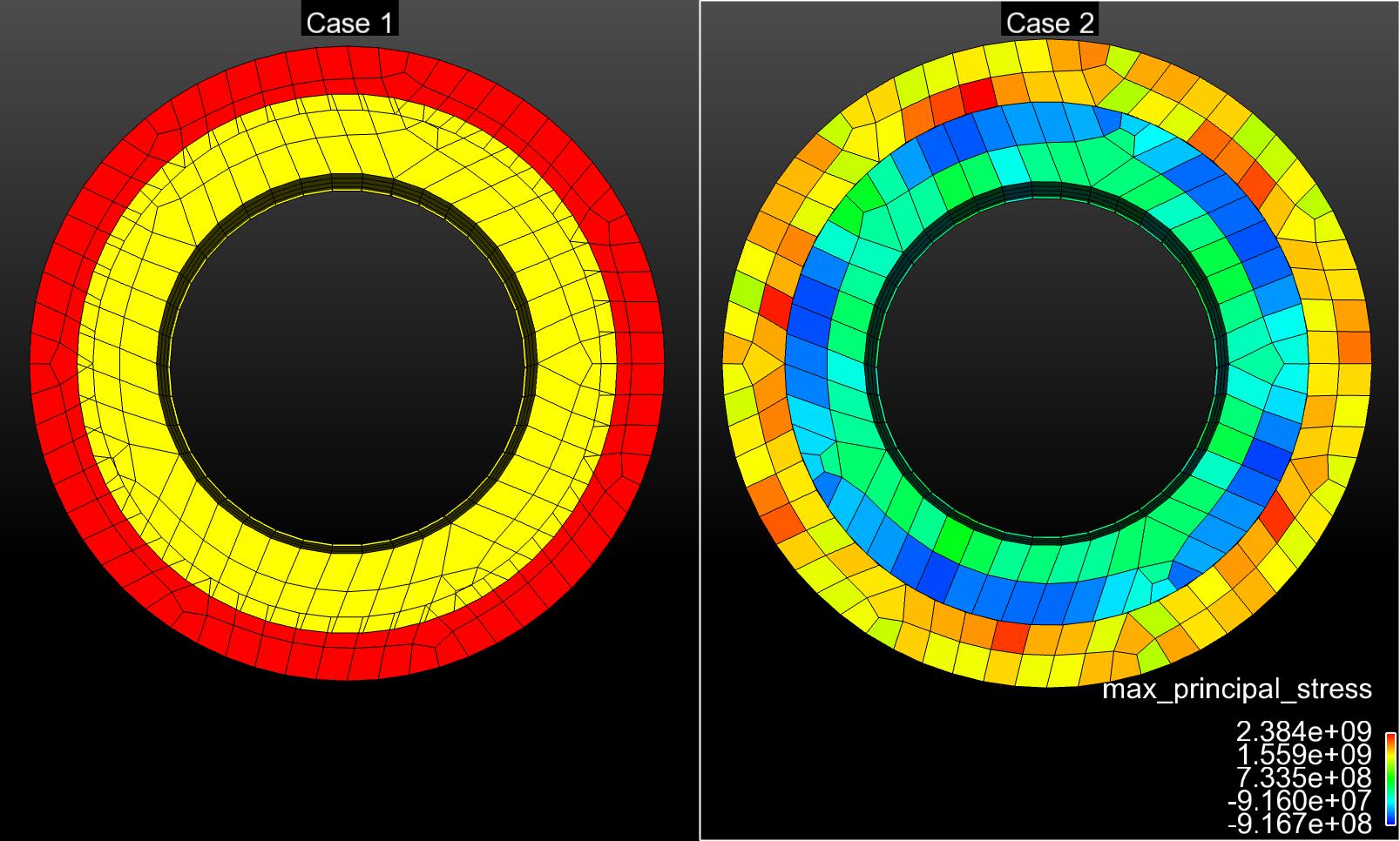
Fig. 24 Stresses experienced after strain and contact is applied
Files
Small overlap
Large overlap