Automated Adaptive Preloading
Product: Sierra/SolidMechanics - Explicit Analysis
Problem Description
This example demonstrates how an automated preload many be applied in an analysis to meet some specific target conditions. There are two analyses presented here. In the first analysis, preload is applied via artificial strain to achieve target clamping forces in a set of bolts. Two nominally equivalent methods are demonstrated for this problem: the automatic method, and the subroutine method. In the second analysis, the target force required to deform a nonlinear part a specified amount is determined.
Bolt Preload Problem
The mesh for the bolt preload analysis is shown in Fig. 14. Each of the three bolts (blue, violet, and red) are are embedded in a fixture block (gray). An artificial strain will be applied to shrink a portion of each bolt (green). The purpose of the preload is to find the correct artificial strain such that each bolt has the correct target clamping force as would be produced by tightening the bolt with a calibrated torque wrench.

Fig. 14 Bolt Preload Mesh
The material model for the bolt preload case is a simple elastic model. The bolts interact with the fixture block via contact. The bottom surface of the blue and red bolts are tied into the fixture block. All other contacts are frictional Coulomb contact.
The bolt model is loaded slowly in explicit transient dynamics in way to enable a mostly quasistatic response. A viscous damping block with a small velocity damping coefficient is used to damp out high frequency response and accelerate convergence to the quasistatic solution.
There are two nominally equivalent methods of finding the necessary artificial strain. The first method (automatic preloading method) is recommended for basic bolt preloading, while the subroutine method may be used in specialized cases that may not be possible with the automatic method.
Automatic bolt preloading method The automatic preloading method is designed to offer users a simple and direct syntax for preloading bolts. Preloading is accomplished primarily with a single command line:
preload bolt block_201 to target internal force = 1e7 in direction global_z
Here, block_201 is the shank to be preloaded to a target internal force of 1e7, the the global-z direction. This one line command does everything necessary to achieve the target preload. In fact, the automatic preloading method uses many of the same capabilities as the subroutine preloading method, but with much cleaner and more direct syntax for the user. The automatic bolt preloading method uses the same solver as the subroutine method so a good initial guess for the required artificial strain is necessary. This value is calculated automatically from the material properties and geometry by default, but may also be specified explicitly as a line command initial guess = -2.0e-4. An iteration time may also be specified to change the duration over which a preload increment is applied.
The preloading line command may be repeated any number of times to achieve preloading on multiple bolts, in multiple directions. If the direction is not specified, it is automatically determined as the minimum principal eigenvalue of the inertia tensor. Generally this value will correspond to a bolt axis, but shorter bolts may require the preloading direction be specified manually.
Preload is applied over the entire simulation, unless the ACTIVE PERIODS or INACTIVE PERIODS command lines are present to limit the preload to [a] specific time period[s].
Finally, this example demonstrates the compute internal reactions outputs = on command line which automatically computes the net internal (axial) force in the bolt. A global variable named sm_preload_axial_force_BLOCKNAME is created (where BLOCKNAME is the block name being preloaded. This output variable can be used to monitor the preloading process.
The user is encouraged to read the user manual section on automatic bolt preloading for additional details on this capability.
Subroutine preloading method In the subroutine preloading method, the requisite artificial strain is solved for by combining a number of specialized capabilities with a library user subroutine. Ultimately the actual artificial strain is applied by two ‘begin artificial strain’ blocks. Blocks 201 (blue bolt) and 401 (red bolt) are artificially shrunk in the z direction while block 301 (violet bolt) is shrunk in the y direction. The actual shrinkage is controlled by the function ‘bolt_preload’ which is a simple function that just sets the artificial strain to the element value of the variable ‘applied_strain’.
The per element applied strain is defined by a set of user output blocks each running a ‘aupst_preload_solver’ subroutine. The ‘aupst_preload_solver’ subroutine is described in more detail in the Sierra/SM User’s Guide chapter on the user subroutine library. Effectively this subroutine will adaptively update the element variable ‘applied_strain’ until the target criteria is matched.
In this case the target criteria is the global value of the internal force in each bolt (found by the magnitude of the internal reaction within the bolt.) The subroutine takes several parameters. The ‘target_value’ parameter is the target axial preload force in the bolt. The ‘initial_guess’ parameter is the initial guess of the strain required to reach the target force. The closer the initial guess is to the final correct value the faster the solution will be reached. Generally the initial guess should be on the low side to avoid accidentally overshooting the correct solution and causing yield. The ‘iteration_time’ parameter controls how long each ‘load step’ of the preload solver predictor corrector algorithm will be. The iteration time must be large enough that system is able to obtain at least approximate equilibrium within each iteration step. The ‘target_variable’ parameters defines the variable that drives solution. The preload is complete when the value of the ‘target_variable’ reaches the ‘target_value’. The ‘working_variable’ parameter defines where the output of the subroutine will be stored. For this example the subroutine is setting the ‘applied_strain’ variable on each element to be read by the artificial strain block. Finally the user subroutine requires some persistent state data to function ‘bolt_preload_state’ which is defined as a ‘begin user variable’ command block.
Preload Results and Discussion
The resultant forces in the bolts as a function of time are shown in Fig. 15. It can be seen that the bolt forces asymptote up to the correct target values. Additionally the load, evaluate, update cycles of produced by the aupst_preload_solver subroutine are apparent.
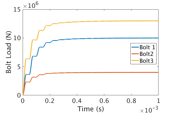
Fig. 15 Bolt Preload Results
Wishbone Problem
The mesh for the wishbone preload analysis is shown in Fig. 16. The purpose of the preload is to find the correct pin forces such that the body is stretched to the correct pin-to-pin length so that it can be placed on another component.
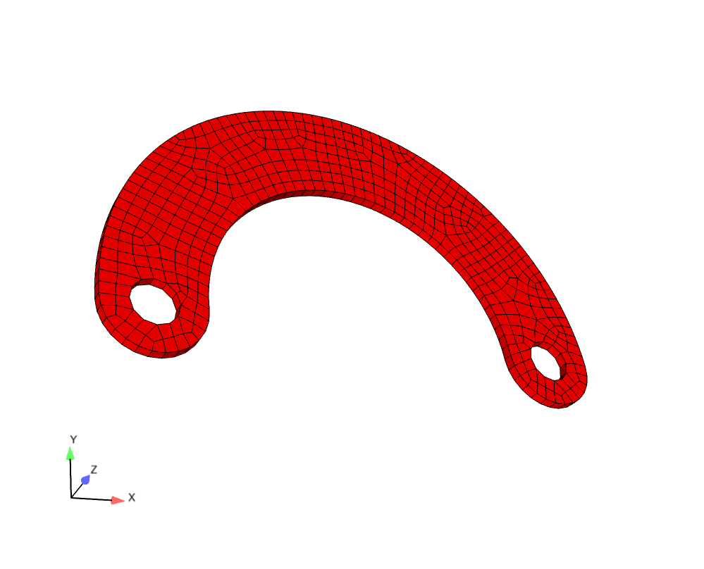
Fig. 16 Wishbone Preload Mesh
The material model for the bolt preload case is a elastic plastic. It is expected that the preload will yield the material making this problem very non-linear.
For this case the model is solved with implicit statics. A handful of additional symmetry constraints are applied to ensure the model remains statically determinate.
As in the bolt preload case the artificial strain is solved for by combining a number of specialized capabilities with a library user subroutine. Ultimately the actual pin force is applied by two ‘begin distributed force’ blocks which apply equal and opposite -X forces to the left pin hole and +X forces to the right pin hole. The distributed force blocks access the function ‘solved_force’ which just sets the net force on each pin equal to a global variable that will be defined by an ‘aupst_preload_solver’ subroutine.
In this case the target variable for the preload solver is the net displacement between the left and right pin holes and the ‘initial_guess’ is a guess of the required force to achieve the displacement. As in the bolt case this initial guess needs to be in the right ball park, but should generally be a low-ball estimate to avoid overshooting the actual solution and causing excessive yield. As in the bolt preload case the user subroutine requires an externally defined state variable field. The only difference in the wishbone case is the user subroutine is operating on global quantities (in the bolt case the user subroutine was operating on element quantities.)
Wishbone Results and Discussion
The forces applied to the pin holes as a function of time are shown in Fig. 17 and the resultant displacement in Fig. 18. It can be seen that the pin-to-pin displacement asymptotes to the correct value. Finally the force displacement curve (applied_force vs. curDisp) for the wishbone is plotted in Fig. 19. The force displacement curve shows the non-linear response of the wishbone and that the preload is effectively terminated at the correct displacement value.
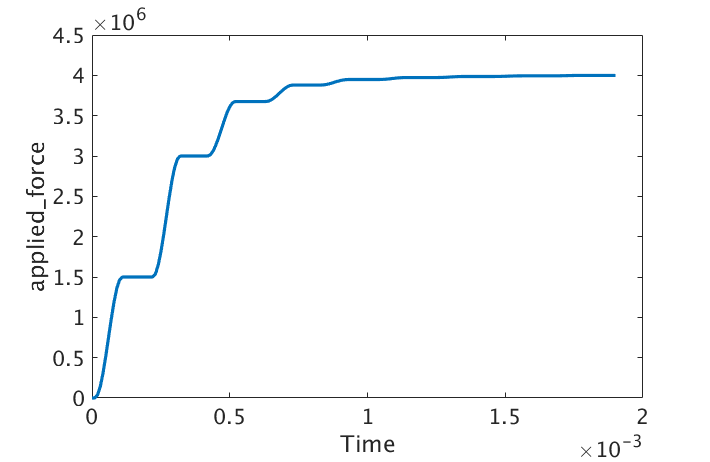
Fig. 17 Wishbone Force Results |
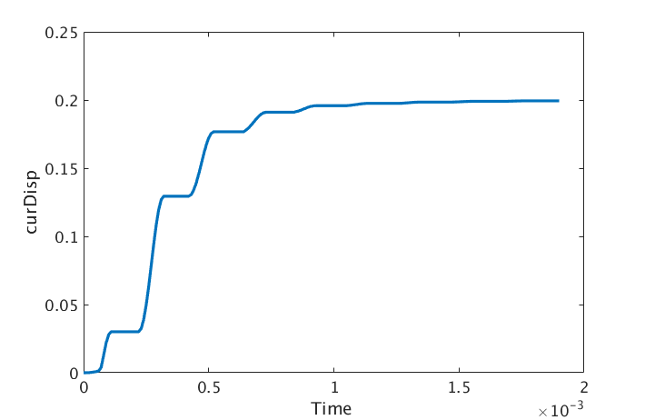
Fig. 18 Wishbone Displacements Results |

Fig. 19 Wishbone Force Displacement Curve |
Files
Bolt Preload Mesh
Wishbone Preload Mesh