Plate Indentation
Product: Sierra/SolidMechanics - Implicit Analysis
Problem Description
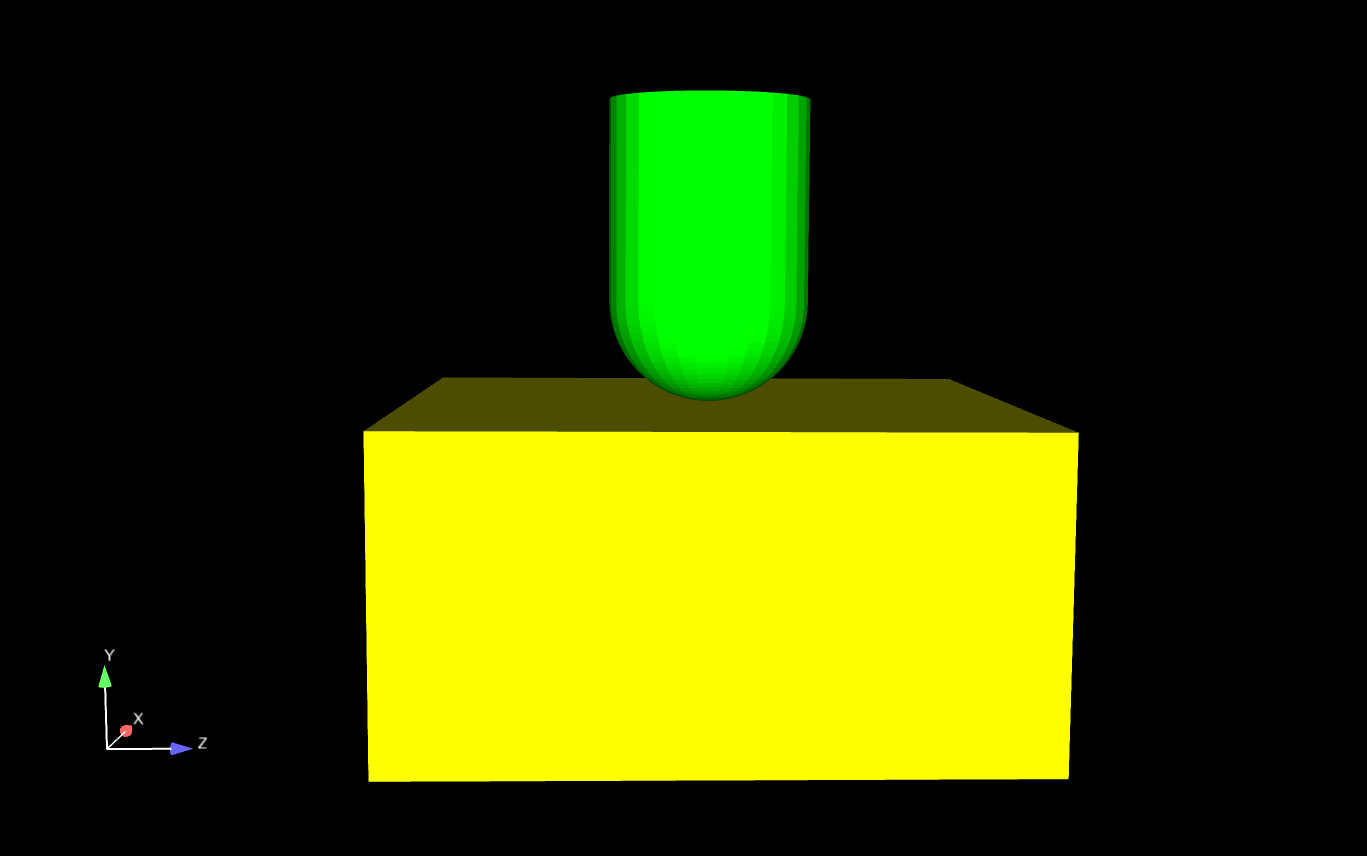
Fig. 53 Thick plate indentation problem.
This test was originally created to replicate a problem from the ABAQUS Example Problem Manual. In the problem, a punch is given a displacement which creates a deep indentation into a thick, malleable plate. However, the size of the displacement could not be replicated so the problem was modified to incorporate only a fraction of the original displacement. The other adjustments to the ABAQUS problem are that instead of the punch displacing, it is now fixed, with the plate pushing up on the punch, and that the problem now tests the full geometry instead of a quarter of the total geometry. The initial configuration can be seen in Fig. 53.
Loading and Boundary Conditions
This example problem contains very few and simple geometries. The bottom surface of the plate is given a prescribed displacement which pushes the plate up into the punch. In addition, the top surface of the punch is fixed in the y direction to ensure the contact between the plate and the punch causes deformation, not displacement. Lastly, a side A-side B relation is used to define contact between the punch and the plate, respectively.
Material Model
The plate uses an elastic material model and is given the properties of a crushable foam. The Young’s Modulus for the punch is set very high to mimic a rigid body. Properties for the crushable foam were obtained from the ABAQUS manual.
Finite Element Model
The total model contains just under 170000 hex elements, with the plate containing 150000 and the punch containing almost 20000. Fig. 54 shows the graded mesh used for the plate.
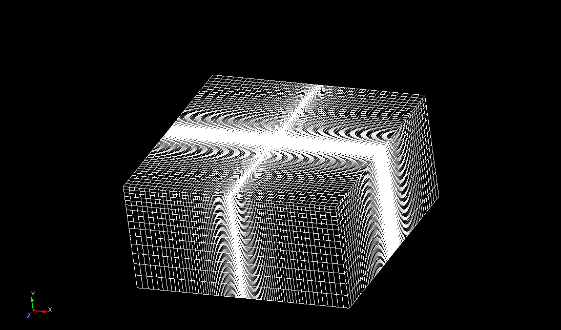
Fig. 54 Graded Mesh
Feature Tested
The primary featured tested in this problem is implicit contact
Results and Discussion
Fig. 55 shows the system at it’s final step, displaying the maximum indentation the plate undergoes. Fig. 56 displays \(1/4\) of the plate, which better shows the contact behavior. When behaving correctly, the plate will not show any wave patterns, and will be as smooth as the mesh allows it. A finer mesh will lend a smoother surface, eventually reaching a perfect curve as the as the mesh intervals go to zero. Figures Fig. 57 and Fig. 58 show the strain developed by the compression of the plate.
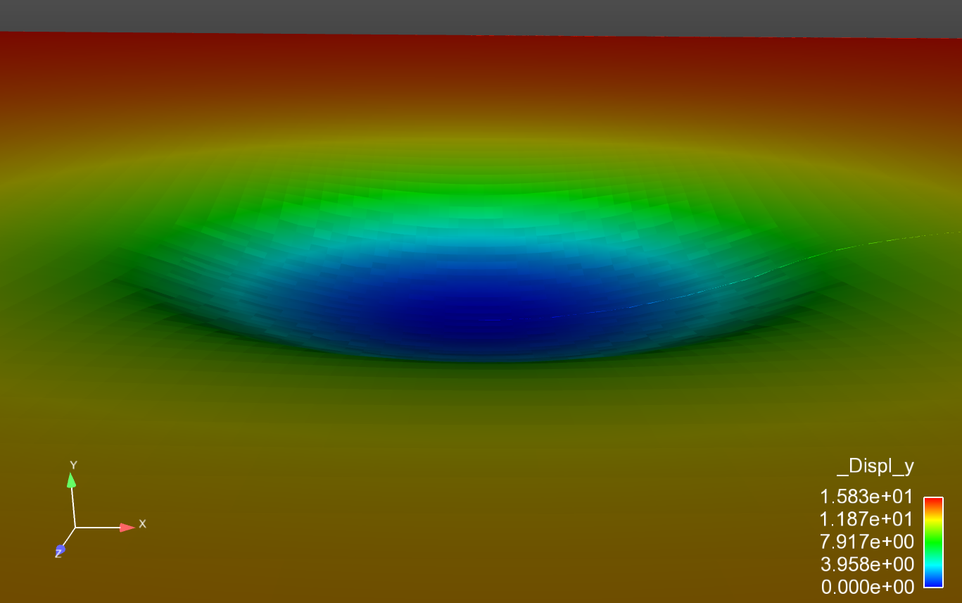
Fig. 55 Final displacement. |
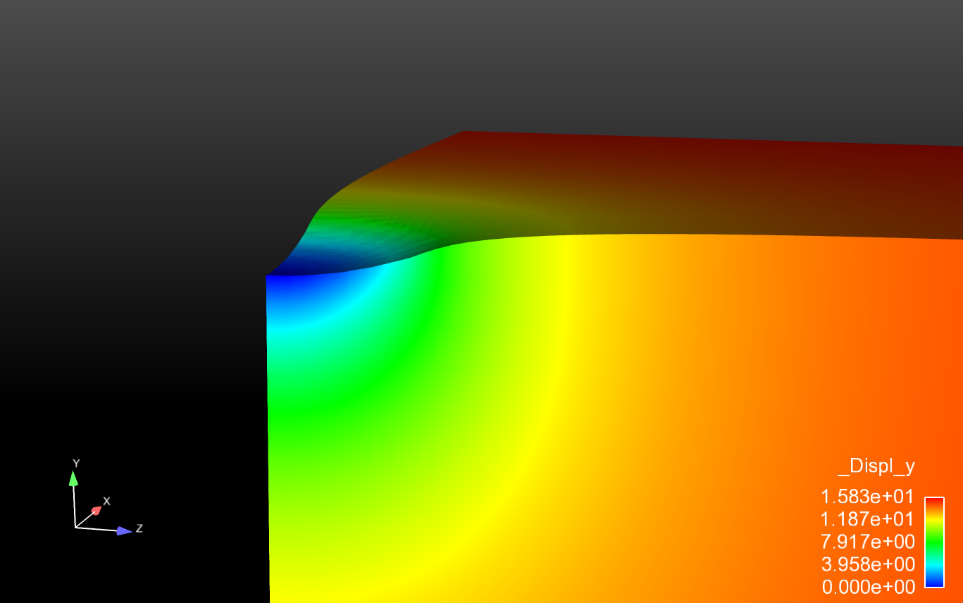
Fig. 56 Final displacement. |
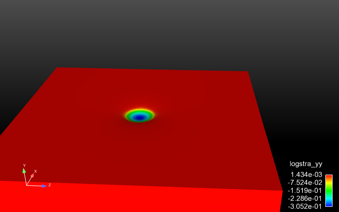
Fig. 57 Final strain. |
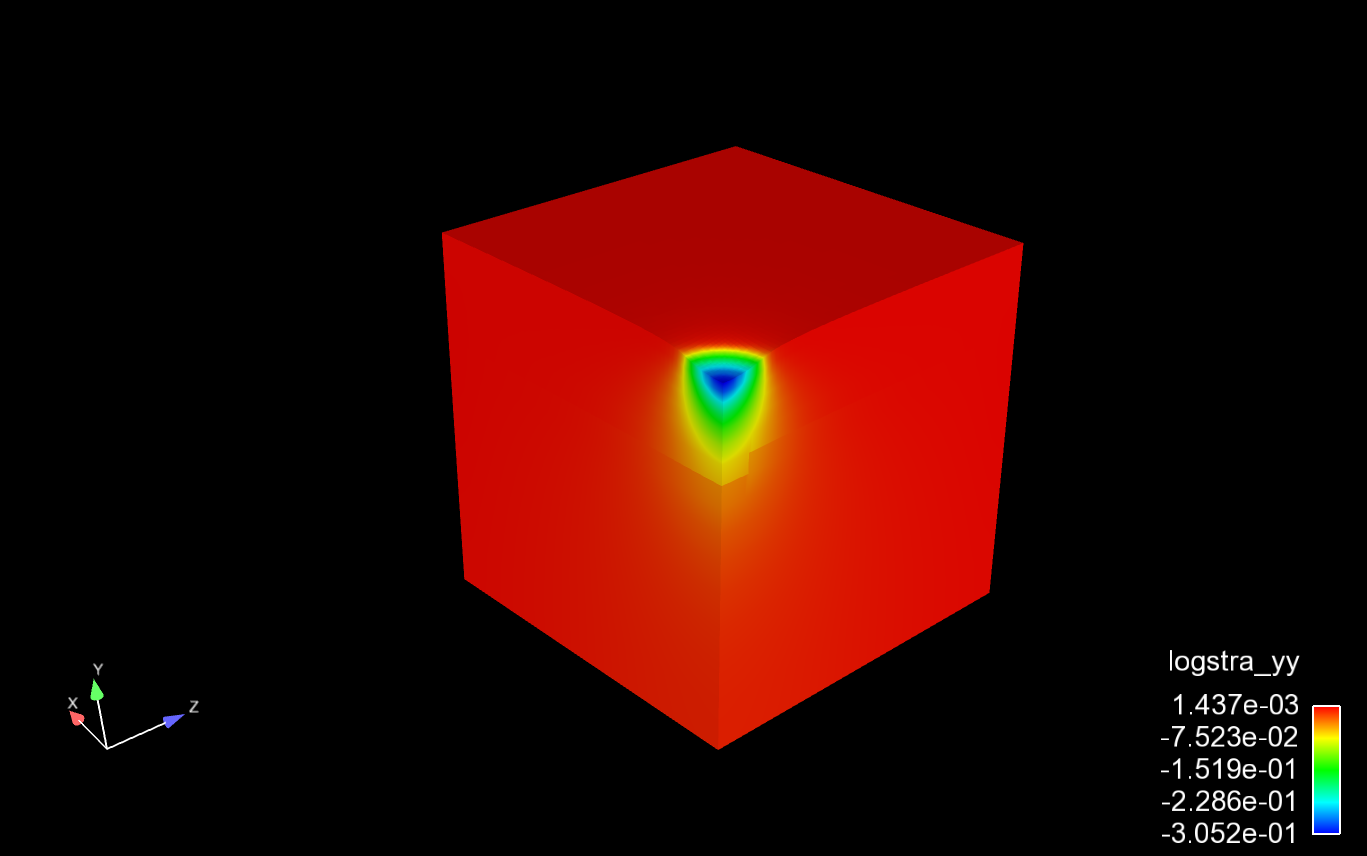
Fig. 58 Final strain. |