Newton Cradle
Product: Sierra/SolidMechanics - Explicit Analysis
Problem Description
This example demonstrates the conservation of momentum and kinetic energy (through basic Newtonian mechanics) within an explicit dynamic analysis with contact. There are currently three geometric cases available for running: the dropping of one, two, and three balls. These cases can be tested through commenting/uncommenting the Genesis files of interest referenced inside the input deck. These configurations can be seen in Fig. 35. The 5 ball-chain system contains a default initial configuration of one raised ball.
The balls are given an initial rotational displacement through their geometrical location specified in Cubit. The at rest balls touch at an initial position as fine as the mesh generated.
Loading and Boundary Conditions
The pendulum wires are defined as a truss section with each of the five balls containing an inner rigid body core. Connected in a v-shaped manner, the uppermost ‘ceiling’ node of the wires define the reference location to each of the five inner rigid body volumes. These rigid bodies are only allowed to rotate along the z-axis and translate along the x-axis and y-axis. Controlling the rigid body displacements in this manner allows one to bypass making the spherical nodeset rigid, hence restricting movement.
A constant and uniform gravitational load is applied to the system.
Material Model
Assuming small deformations and simple linear elastic behavior, the outermost material for each respective sphere is defined in an elastic model. Modulus of Elasticity values were picked out of convenience, i.e., stiff enough for minimal elastic deformation and compliant enough to minimize computational expense for the explicit analysis.
Iterations performed to optimize these parameters conceded the outer sphere’s Young’s Modulus at approximately \(10^4\) times less than that of steel. The inner spheres of the model were defined as rigid bodies.
Metric units are used |
|---|
Displacement: meters |
Mass: kilograms |
Time: seconds |
Force: \(kgm/s^2\) |
Temperature: Kelvin |
Young’s Modulus: Outer Sphere |
E |
\(200\times10^5\) |
Young’s Modulus: Core |
E |
Rigid |
Young’s Modulus: Wire/String |
E |
100 |
Poisson’s Ratio |
\(\nu\) |
0.3 |
Density |
\(\rho\) |
\(7.48\times10^3\) |
Finite Element Model
To eliminate rigid body contact of the outer spheres, mesh creation of this model required independent nodeset specification for inner and outer spherical volumes (see Fig. 36). The overlap of volumes was eliminated by first creating inner and outer spheres of radii 1 and 0.25 units respectively, followed by elimination/recreation of the inner sphere volumes. Both inner and outer spheres were then meshed using a standard four noded tetrahedral mesh.
The wires were given a truss element type.
Feature Tested
Explicit contact and rigid bodies.
Results and Discussion
In an idealized Newton Cradle exhibiting perfectly elastic collisions, the Total Kinetic Energy before and after a collisions would be equal. In reality, the balls are elastic, so some energy is stored in them as elastic Strain Energy of the balls themselves. Moreover, artificial bulk viscosity is used by default to damp out the high frequency responses from the system. Artificial viscosity is dissipative and so removes Total Energy from the system, hence Kinetic Energy is not conserved.
The Internal Energy is calculated as the sum of the nodal internal forces times the nodal velocities, integrated over time. In contrast, the Strain Energy is calculated as the stress times the strain rate integrated over time. The Internal Energy includes dissipated energy due to artificial viscosity and stored energy associated with hourglass modes which are not accounted for in the Strain Energy. The difference in Internal Energy and Strain Energy normalized by the Maximum Initial Potential Energy can be seen in Fig. 37. At sphere-to-sphere contact initiation, steep rates of change in Internal Energy and Strain Energy are present, followed by an approximately constant period when the opposing ball rebounds. This stair-step cycle continues with subsequent oscillations of the Newton Cradle. System energy conservation, including Kinetic, Internal, and Potential Energy, is presented in Fig. 38. The increasing Internal Energy over the simulation can be attributed to bulk viscosity.
At 20 seconds of test run time under the configured geometries and loading, the Newton Cradle will swing for approximately 2 periods. The run time for energy dissipation of the system can be carried out as desired through input deck specification.
Energy Variables |
|
|---|---|
Kinetic Energy |
KE |
Internal Energy |
IE |
Potential Energy |
PE |
Strain Energy |
SE |
Total Initial Energy |
TIE |
 1 ball
 2 balls
 3 balls
Fig. 35 Initial Configurations
Fig. 36 Rigid Body Highlight
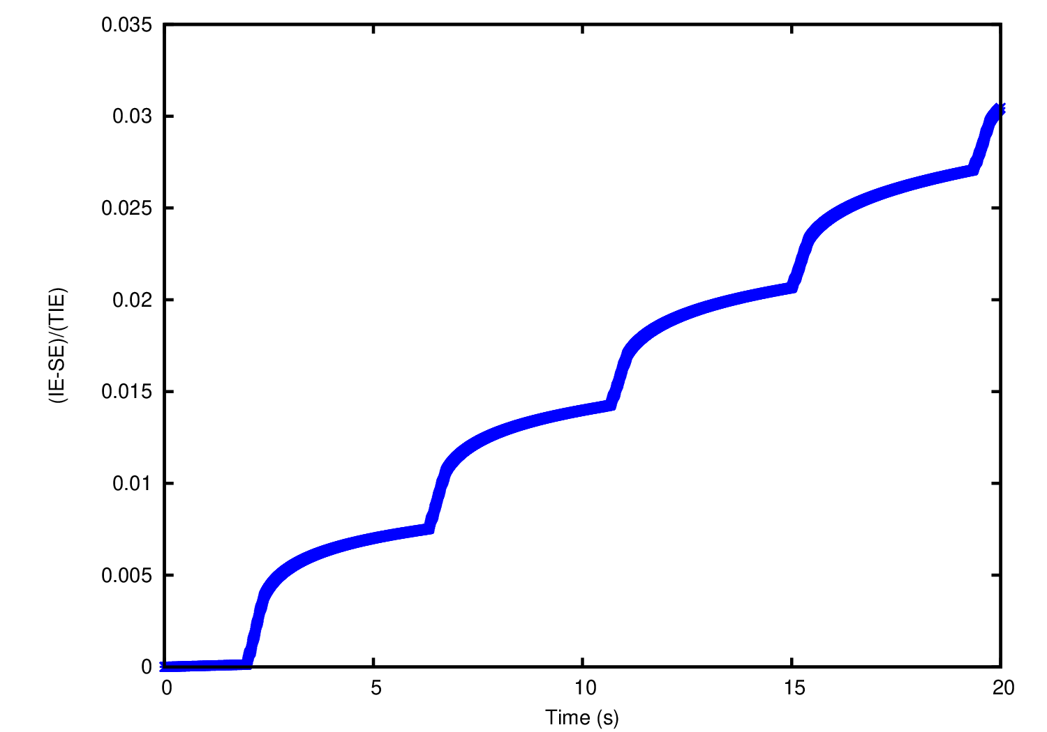
Fig. 37 Normalized Dissipation Energy
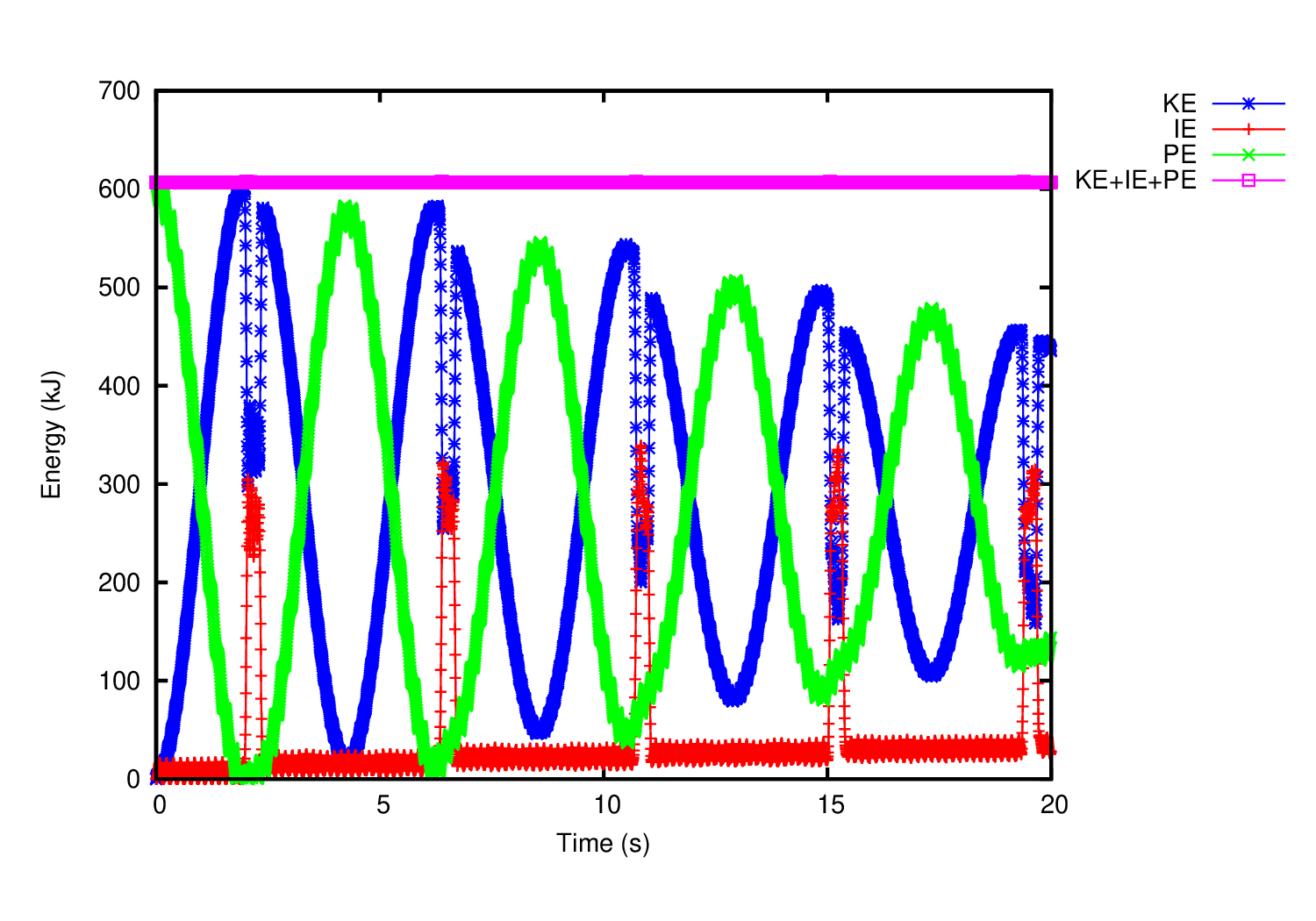
Fig. 38 Energy History