14. Element Basics
14.1. Properties of Shape Functions
In this chapter we explore the basic issues associated with the design of finite elements, which are the building blocks of the methods we have discussed. In particular we will discuss how definitions and manipulations are done at the local level to produce the elemental quantities, like \(\mathbf{m}^e\), \(\mathbf{f}^\text{int}_e\), and \(\mathbf{k}^e\), that are needed for assembly and solution of the global equations of motion. We concentrate in this chapter on one-field problems, i.e., where only the deformation mapping \(\varphi_t\) is discretized. It will turn out that many nonlinear solid mechanics applications of interest, including nearly incompressible elasticity and metal plasticity, require more sophisticated approximations in which other variables (like pressure) must be explicitly included in the formulation.
To start, we discuss in general terms the requirements usually placed upon shape function definitions. It should be noted that these conditions are sufficient but not necessary, so that many formulations exist that violate one or more of them. However, it is also fair to say that most finite elements in wide use satisfy the conditions we will discuss.
The first condition relates to convergence of the finite element method in general, and the implication on properties of shape functions for elements. We begin by defining \(m\), which will denote the highest order shape function spatial derivative present in the expression for the stiffness matrix. For the class of problems we have considered so far, we find from Section 13 that the element stiffness takes the form
The internal force vector required in (14.1) was given generically in Section 10, equations (10.43) and (10.44), as:
Performing the differentiation indicated in (14.1) will produce no higher than first-order derivatives of the shape functions; therefore \(m=1\).
The three general convergence requirements we need to mention are as follows:
The global shape function \(N_J\) should have global continuity of the order \(m-1\). In mathematical terms, they should be \(C^{m-1}\) on \(\Omega^h\).
The restriction of the global shape functions to individual elements (i.e., the \(\left\{ N_J \right\}\)) should be \(C^m\) on the element interiors.
The elemental shape functions \(\left\{ N_J \right\}\) should be complete.
The first two of these requirements are fairly simple to understand. The first, \(C^{m-1}\) continuity requirement, simply means that all derivatives up to \(m-1\) of the shape functions should not undergo jumps as element boundaries are crossed. In the current case this means that all \(N_J\) should be \(C^0\) continuous. Since the approximation to the configuration mapping \(\varphi^h_t\) is a linear combination of these shape functions, we see that the physical restriction placed by this condition amounts to no more that a requirement that the displacement be single-valued throughout the domain (i.e., gaps and interpenetrations at element boundaries may not occur).
The second requirement on element interiors simply states that the shape functions should be sufficiently smooth so that the element stiffness expressions are integrable. Physically speaking, the first derivatives of the configuration mapping produces strain measures, so we simply require that the strains be well-behaved on element interiors by this restriction. Note that global smoothness of the strains (and therefore stresses) is not required. This point is of some importance in the reporting of results, as we discuss later.
The third requirement, the completeness requirement, is somewhat more involved to explain and yet corresponds fairly directly to physical ideas. We say that a given element is complete when setting the element degrees of freedom according to a given low-order polynomial forces the solution \(\varphi^h_t\) to be interpolated according to the same polynomial point wise in the element. The degree of polynomials for which we place this requirement is referred to as the degree of completeness for the element.
In the current case where we deal with solid continua, the usual degree of completeness demanded is 1. This means that all global solutions representable by polynomials, up to and including order 1, should be exactly representable by the element. It is worthwhile to consider an example of this point. Suppose we are in three dimensions and set element degrees of freedom via
where \(c_0\), \(c_1\), \(c_2\), \(c_3\) are arbitrary constants and \(X^e_a\), \(Y^e_a\), \(Z^e_a\) are the reference coordinates for local node number \(a\). The completeness condition requires that
hold for all \(\mathbf{X}^e \in \Omega^e\) and for all values of the arbitrary constants.
14.1.1. Element patch test
As mentioned above, the completeness requirement has a physical interpretation as well. In solid mechanics we have already pointed out that the first spatial derivatives of the displacements produce strains. Since we require that an element be able to reproduce arbitrary global solutions that are linear polynomials, this also implies that any state where the first derivatives (i.e., strains) are constant should be exactly representable. Thus a complete element should be able to exactly represent any uniform strain state. A practical way to test for this condition is to impose a boundary value problem on an arbitrary patch of elements having a constant strain (and thus stress) solution and then demand exactness of the numerical solution. Such a test is called a patch test and has become one of the standard benchmarks by which any new proposed element formulation is tested and evaluated.
A particularly useful instantiation of the patch test is to prescribe a combined rigid body rotation and stretch, making use of all of the constants \(c_0\), \(c_1\), …, as depicted graphically in Fig. 14.1. Here a piecewise combination of global linear function are specified.
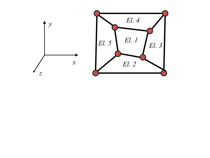
Fig. 14.1 Element Patch test in 2D.
14.2. Parameterization
With these three criteria in hand for element definitions, we proceed to define a recipe through which element definitions and manipulations can be systematically performed. The most basic definition to be made toward this end is the concept of the local (or parent) parameterization of an element. In effect we seek to define a local coordinate system that will be the same for every element in a problem, which contributes in great part to the modularity we will desire for element level operations.
We will denote a vector of these local variables by \(\mathbf{r}\), with \(\mathbf{r}\) being a 2-vector in two dimensions and a 3-vector in three dimensions. Specifically, we define \(\mathbf{r}\) as
The local variables \(r\), \(s\), and \(t\) are all assumed to range between \(-1\) and \(1\), so that the domain definition is likewise standardized among all elements of the same type in a given problem. The domain of \(\mathbf{r}\) is often referred to as the parent domain. As shown in Fig. 14.2, the two dimension parent domain is a bi-unit square, and in three dimensions a bi-unit cube.

Fig. 14.2 Local parameterization and coordinate mappings in two and three dimensions.
Of course, for this alternative element coordinate system to be of practical use, its relationship with the global coordinate system must be defined. This is accomplished through a shape function expansion via
where \(\mathbf{X}^e\) is the global (reference) coordinate mapping covering element \(e\) and where \(\mathbf{X}^e_a\) are the element nodal (reference) coordinates, as before. Note also in (14.6) that the shape functions have been written using the parent coordinates as the independent variables. This is the reason for the superposed tilde on the shape function. One could think of \(\mathbf{r}\) as a material point label within the element, so that \(\mathbf{X}^e\) and \(\mathbf{r}\) are two reference coordinate systems for the element that are related according to (14.6). The most important generic class of finite elements is comprised of isoparametric elements. Such elements are defined by utilizing the same shape functions for definition of deformation \(\varphi_t^h \left( \mathbf{X}^e \right)\) as for the element coordinates \(\mathbf{X}^e\). One can show that, providing all element shape functions sum to one at any point in the element, an isoparametric element automatically satisfies the completeness condition. Furthermore, provided the shape functions are also suitably smooth on the element interior and match neighboring element descriptions on element boundaries, all three of the conditions required for convergence are met by isoparametric shape functions.
There are important implications of the isoparametric approach for the Lagrangian description of large deformation solid mechanics. The implications are related to the restrictions imposed on the mapping from the parent domain to the physical domain. So that we may distinguish carefully between mappings taking \(\mathbf{r}\) as an argument and those taking \(\mathbf{X}\), we will use the superposed tildes for the former, as in (14.6). If an element is isoparametric, then by definition the configuration mapping over an element is given by
where the shape functions \(\tilde{N}_I (\mathbf{r})\) are exactly the same as in (14.6). However, it should also be the case that the function \(\tilde{\varphi}_t^h (\mathbf{r})\) should be obtainable from the composition of \(\tilde{\varphi}_t^h (\mathbf{X}^e)\) defined according to (14.4) with \(\mathbf{X}^e(\mathbf{r})\) defined according to (14.6). Thus we can write:
Comparing the leftmost and rightmost expressions of (14.8) and realizing that the equality must hold for any given combination of the element degrees of freedom \(\mathbf{d}_I^e\), we are led to conclude that the alternative shape function expressions \(\tilde{N}_I (\mathbf{r})\) and \(N_I \left( \mathbf{X}^e \right)\) must be related by composition via
Thus we have the option of defining the shape functions over whatever domain is convenient, and since the parent domain is the one that is standardized, we typically begin with an expression for \(\tilde{N}_I\) and then derive the implied expression for \(N_I\) according to
(14.10) reveals the important implications as a practical condition on the inverse mapping \(\left(\mathbf{X}^e\right)^{-1}\) of \(\mathbf{X}^e\). It must be well behaved for the shape function \(N_I\) to make sense.
Fortunately, according to the implicit function theorem, the inverse function to (14.6) is smooth and one-to-one provided the Jacobian of the indicated transformation is nonzero. This essentially amounts to a geometric restriction on elements in the reference domain. In two dimensions, e.g., the implication is that all interior angles in each 4-noded element must be less than 180 degrees.
Finally, let us consider shape functions that take the current coordinates, \(\mathbf{x}^e = \varphi_t^h \left(\mathbf{X}^e \right)\). Such an expression is needed in (14.2) where the spatial derivatives in the current configuration are needed:
where we have temporarily introduced the additional notation \(\hat{N}\) to indicate that the shape function takes the current coordinate.
Following similar reasoning as above, one can conclude that the functions \(\hat{N}\) must obey
Again for the needed function \(\left(\tilde{\varphi}_t^h\right)^{-1}\) to be well-behaved, the Jacobian of the transformation ((14.7) must be non-zero. This amounts to:
Provided the original element definitions are not overly distorted, the second term on the right hand side of (14.13) will be non-zero. Thus the well-posedness of the spatial shape functions \(\tilde{N}_I\) requires that \(\det \left[ \frac{\partial \tilde{\varphi}_t^h}{ \partial \mathbf{X}^e} \right]\) be non-zero. Notice, though, that this is an approximation of the determinant, \(J\), of the deformation gradient, as defined in Section 5. According to (5.10), \(J\) must be positive point wise for the concept of volume change to have any physical meaning. Thus, provided the approximated deformation mapping remains kinematically admissible (i.e., \(J>0\)), the spatially defined shape functions are guaranteed to be well-behaved.
With this discussion as background, we now turn our attention to definition of the shape functions according to the parent domain. To keep the notation complexity to a minimum, we will drop the explicit distinction between \(N_I\), \(\tilde{N}_I\), and \(\hat{N}_I\), referring to all these objects as simply \(N_I\).