4.2.1. Finite element model
The model discretization (mesh database) and the mesh components to be used in
the model are defined at the Sierra scope and are later referenced by the
application at the Region level. Specification of a mesh database and
association of material properties with portions of the mesh are defined within
the Finite Element Model command block. In coupled analyses the need often
arises for different discretizations of the same physical domain. In this case
one must supply a different Finite Element Model command block for each
discretization since only a single mesh can be referenced within this command
block.
4.2.1.1. Defining the Mesh Database and Decomposition Method
The mesh database can be defined as follows:
Database name {=|are|is} <StreamName>
Where the <StreamName> is the base name containing the output or input mesh.
If the filename begins with the / character, it is an absolute path;
otherwise the path to the current directory (where the input file is) will be
prepended to the name. If this command line is omitted, then an assumed filename
is used; this will be the basename of the input file with a .g suffix
appended. The most commonly used database formats are Exodus and Genesis (.e
and .g suffix, respectively). The database type defines the format used for
the input/output mesh:
The mesh can be partitioned across processes for parallel runs through a variety of decomposition methods; the particular method used can be defined with the following command line:
Decomposition Method {=|are|is} <MethodName>
The most commonly used parameters for <MethodName> are rcb (Recursive
Coordinate Geometric Bisection) and rib (Recursive Inertial Bisection). If
this command line is not specified, then the default method is rcb if the
input mesh file is not already pre-decomposed. A simple example of defining a
database name and its decomposition method for a finite element command block
is shown below:
Begin Finite Element Model The_Model
   Database Name = the_mesh.g
   Decomposition Method = rib
End
4.2.1.2. Mesh Database Part Names and Assemblies
The input mesh database can be created by a variety of mesh generators. These mesh databases can contain parts of the mesh that either have user-defined names or utilize a default internal naming convention used for the meshed entity/part with a numbered index (e.g. surface_1, block_8). Fig. 4.1 below shows an example of a mesh using the default enumerating scheme.
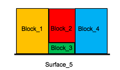
Fig. 4.1 Enumerated blocks
In the following sections, we will refer to Fig. 4.1 to demonstrate example commands of setting up
the finite element model command block.
4.2.1.3. Mesh Part Material Assignments
Assignment of the associated material can be accomplished using a command block:
Begin Parameters for Block block_2
  material air
End

Begin Parameters for Block block_3
  material air
End

Begin Parameters for Block block_1
  material air
End

Begin Parameters for Block block_4
  material air
End
This individually assigns a material air to the all of the blocks in Fig. 4.1. The above command block can be further shortened by assigning materials to more than one block at a time:
Begin Parameters for Block block_1 block_2 block_3 block_4
  material air
End
Finite Element Model shows a summary of commands used to assign materials to parts of the mesh.