9.6. User-Defined Gap Calculations
9.6.1. Background
When running Sierra/SM calculations, it is a common need to compute distances between two components or to compute max/minimum gaps between two components. Based on the problem setup, various algorithms are necessary in order to capture the expected quantity of interest. The section below details these algorithms, and explains the strengths and shortcomings of each.
Each algorithm first computes a nodal distance. Then, if global quantities are desired, global reductions may be performed on the nodal variables, or single line commands may also be used.
See section Section 9.4 for more details on full User Output Syntax.
9.6.2. Computing the Max/Min of a Nodal Closest Distance
BEGIN USER OUTPUT
  surface = surface_1
  COMPUTE NODAL closest_distance AS CLOSEST DISTANCE TO surface_2
END
The first and simplest distance calculation is to compute a nodal closest distance between parts. In this algorithm, the closest distance is computed between all nodes in the source surface (surface_1 in this case) and all faces in the target surface (surface_2 in this case). All nodes in surface_1 should be assigned a distance value, and nodes not in surface_1 are assigned a value of -1. The results of a nodal closest distance calculation can be seen below for a number of different geometries:
Fig. 9.12 Corner gap results using closest distance algorithm |
Fig. 9.13 Moving pin in hole results using closest distance algorithm |
The global max/min gap can then be computed via the below sierra command block:
BEGIN USER OUTPUT
  compute global max_gap as max of nodal closest_distance
  compute global min_gap as min of nodal closest_distance
END
9.6.3. Computing the Max Normal Gap Between Mesh Entities
BEGIN USER OUTPUT
  surface = surface_1
  COMPUTE NODAL normal_gap AS MAX NORMAL GAP BETWEEN surface_2
END
The next distance algorithm to explore is the max normal gap user output calculation. In this algorithm, the max normal gap is computed between all nodes in the source surface (surface_1 in this case) and all faces in the target surface (surface_2 in this case). The max normal gap calculation is achieved by first computing the normals of every node in the source surface. Then, rays are created using the node normals, and a ray search is performed to determine which faces intersect the ray on the target surface. If an intersection is found, a node-face closest point projection is calculated, the normal distance between the source point and the projection point is computed. Nodes not in surface_1 are assigned a value of -1, in addition to nodes in surface_1 whose normal rays do not intersect with any faces in surface_2. The results of max normal gap calculations can be seen below:
Warning
When the rays constructed from the node normals do not intersect any faces of the target, these nodes will receive a value will be -1.
Fig. 9.17 Moving pin in hole results using closest distance algorithm |
Fig. 9.18 Node normals for the moving pin in hole problem |
The global max/min normal gap can then be computed via the below sierra command block:
BEGIN USER OUTPUT
  compute global max_gap as max of nodal normal_gap
  compute global min_gap as min of nodal normal_gap
END
Additionally, a one line command can be used to compute the max gap:
BEGIN USER OUTPUT
  surface = surface_1
  COMPUTE GLOBAL max_gap AS MAX NORMAL GAP BETWEEN surface_2
END
9.6.4. Cases Where the Gap Calculations Yield Different Results
In most cases, both algorithms compute the same result, or very close to the same result. However, in some cases, one gap calculation is required to achieve the desired QOI.
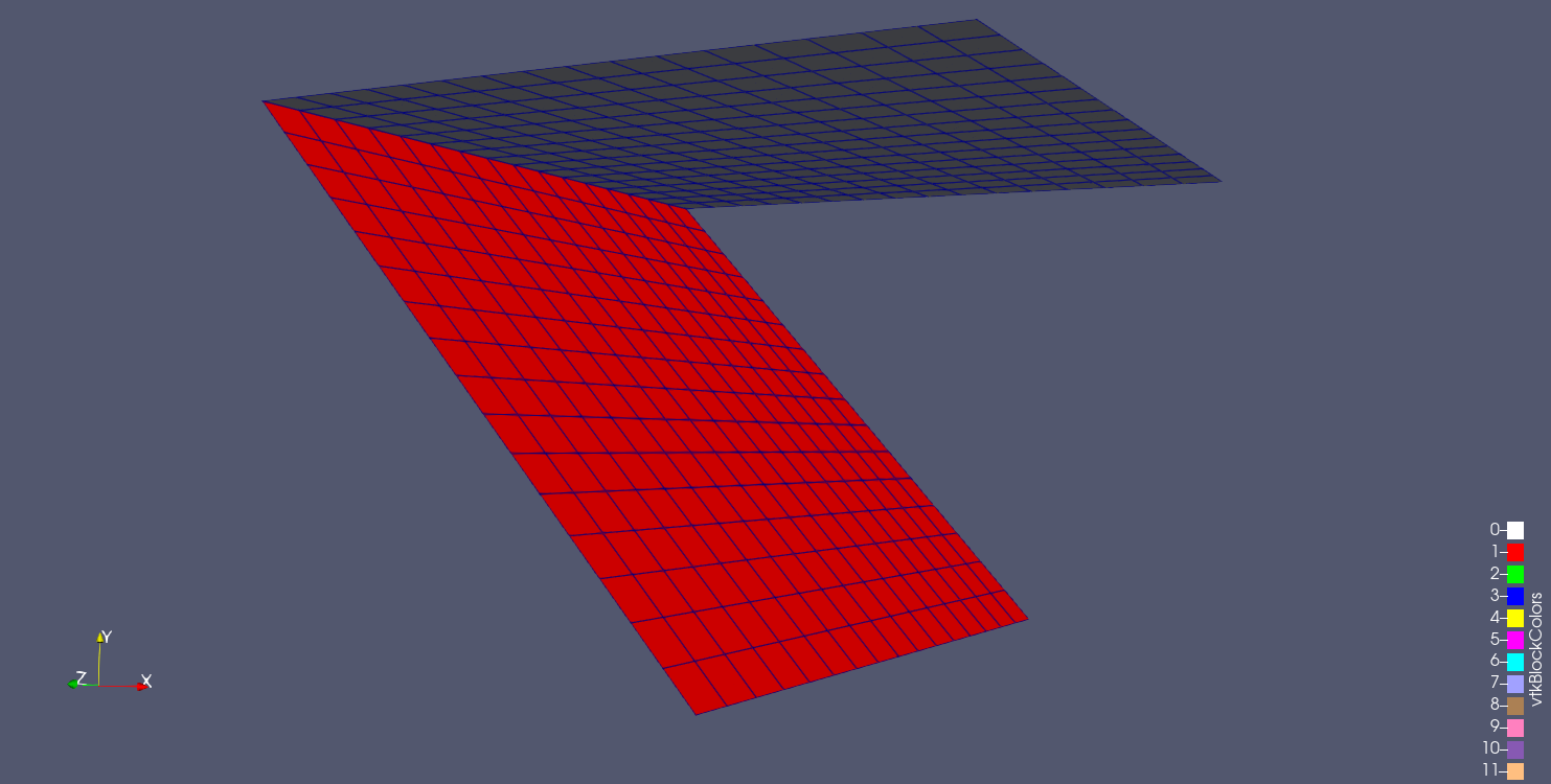
9.6.4.1. Two Cylinders Bolted Together
For the non-matching sideset case, consider the problem of computing the max gap between two cylindrical parts bolted together:
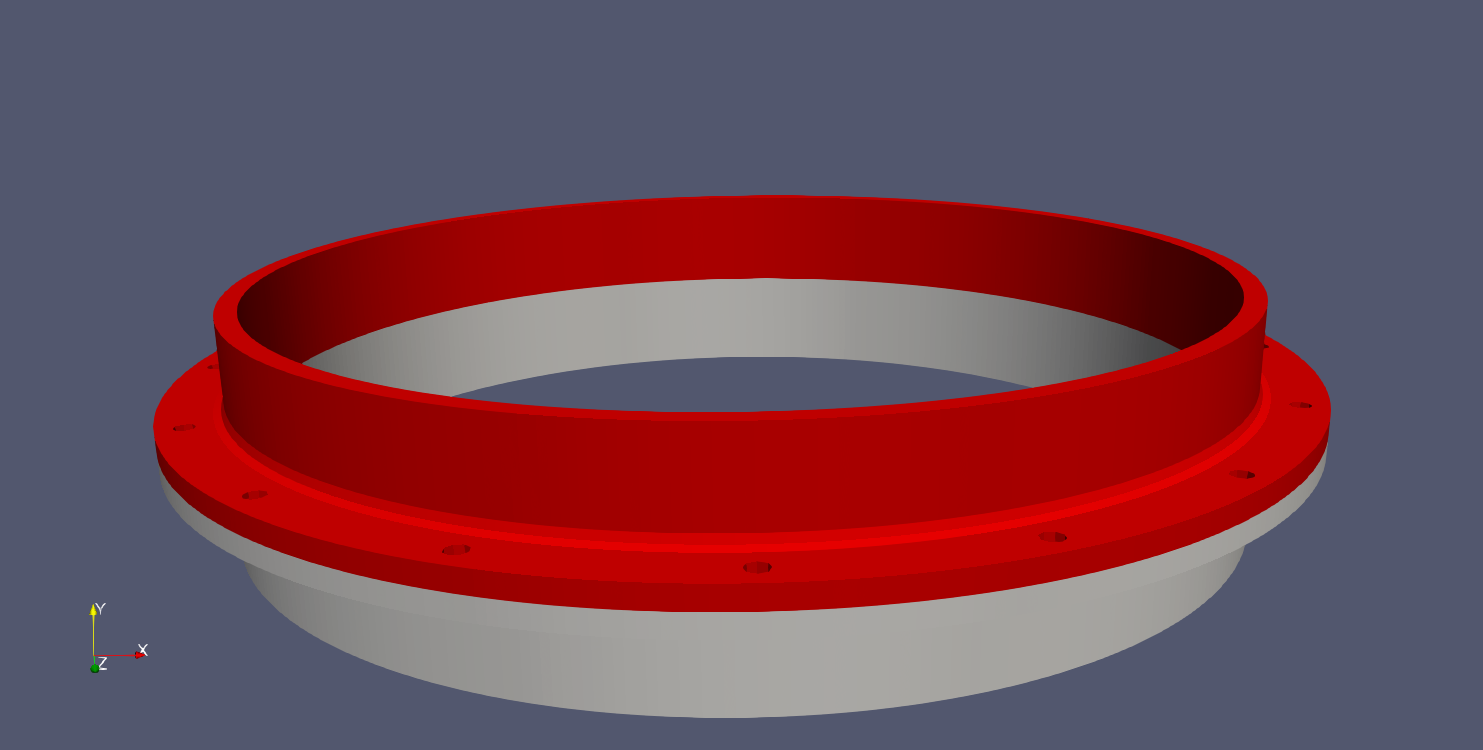
If the use case is to simply compute the max gap between a single surface on the bottom of the red block and the top of the grey block, both algorithms work as expected (the expected gap at this point is near zero).
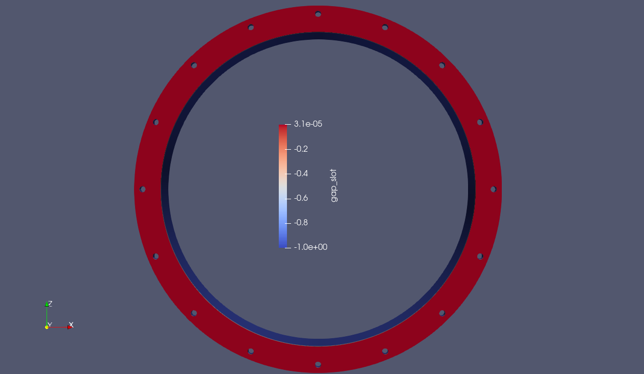
Fig. 9.21 Result using closest distance algorithm |
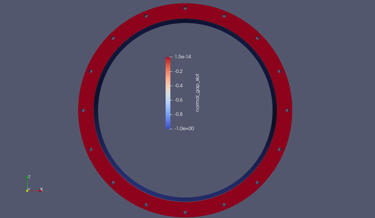
Fig. 9.22 Result using max normal gap algorithm |
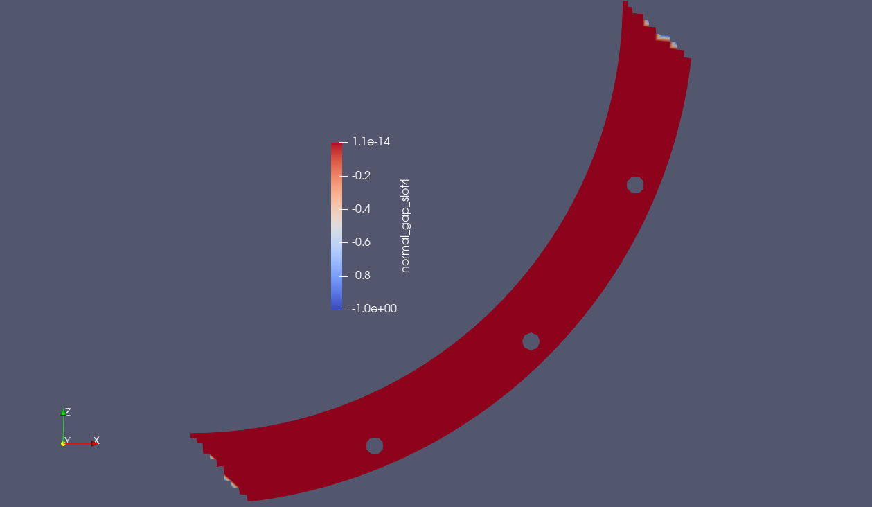
However, suppose you are interested in which quadrants have the max normal gap. Therefore, you divide the sidesets of the two cylinders into four separate quadrants like below:
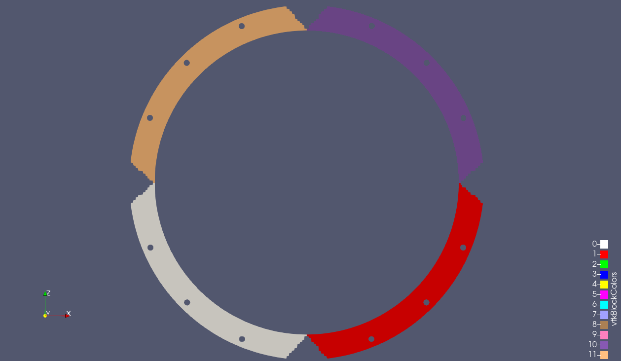
You run the closest distance algorithm on each quadrant, but the results you get back are not what you expect:
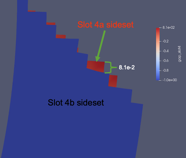
Instead of the near zero value, you now get a closest distance value that is orders of magnitude higher. Why is this? As you can see in the image below, this is due to the non-matching sideset specifications on the top and bottom cylinders. Because some nodes on the source sideset lie outside of the target sideset, the closest distance is a the face that is tangentially closest to them.
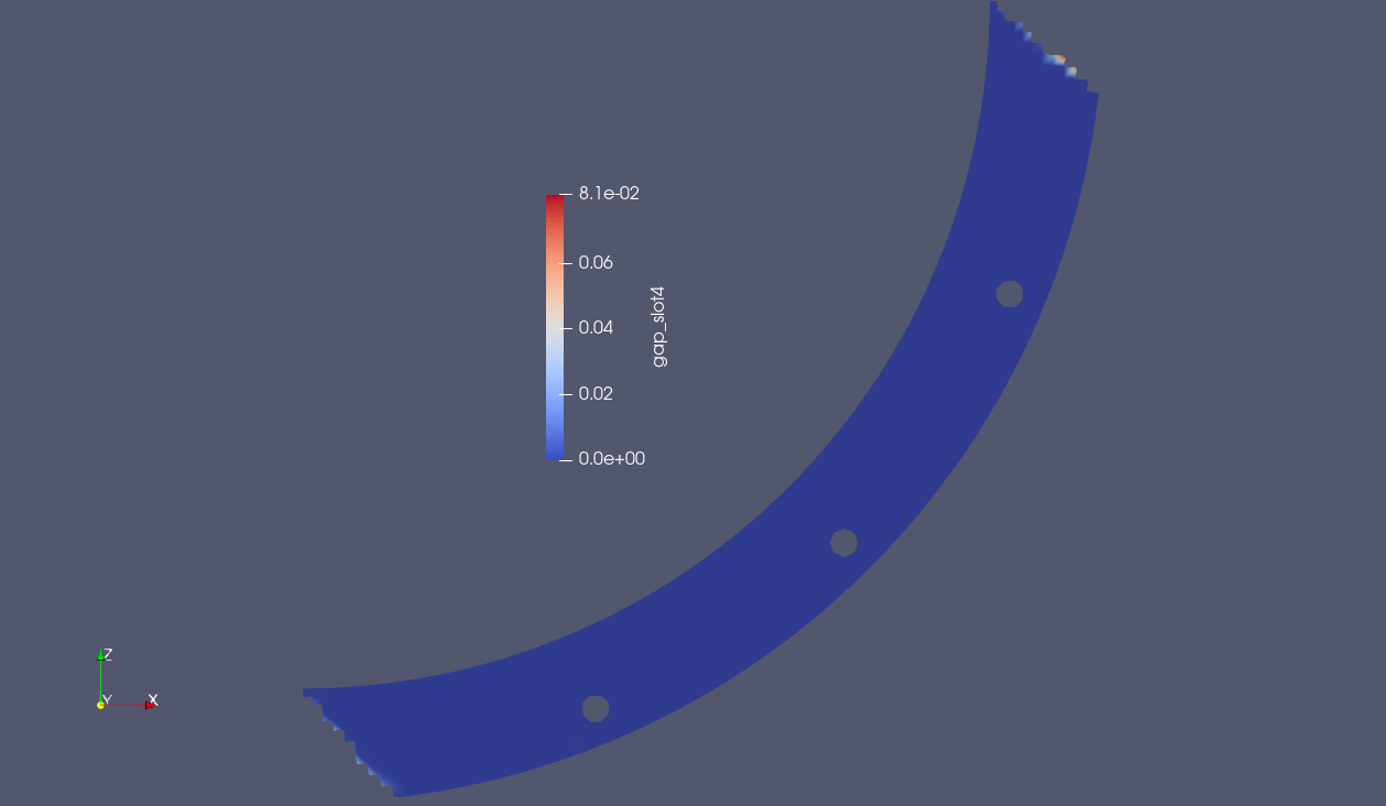
However, when running the max normal gap algorithm, the results are as expected:
9.6.4.2. Single Cylinder in Compression
Another use case where this is required is computing the max gap across a single part; consider the case of wanting to compute the maximum gap of a cylinder being compressed. The gap is computed between the nodes of the cylinder (block_1) and the faces of the cylinder (block_1). The results of computing the closest distance can be seen in the below video.
As you can see, the nodal closest distance is computed as zero, because all nodes are directly connected to their closest faces. However, when the max normal gap option is used, the expected result is achieved.
The expected max gap at full compression is approximately 2.1, which this algorithm predicts very well.
9.6.4.3. Gap Between Angled Shells
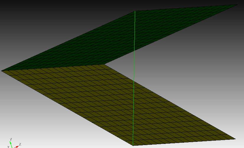
Finally, suppose you would like a max gap calculation for an angled geometry like that shown in the image below:
Intuitively, it would seem the desired max gap quantity of interest should be between points on opposite ends of each side of the angle:
This would achieve a max gap value of 7.65367 in this example. However, when we run both of our max gap between surfaces algorithms, we do not achieve the desired result:
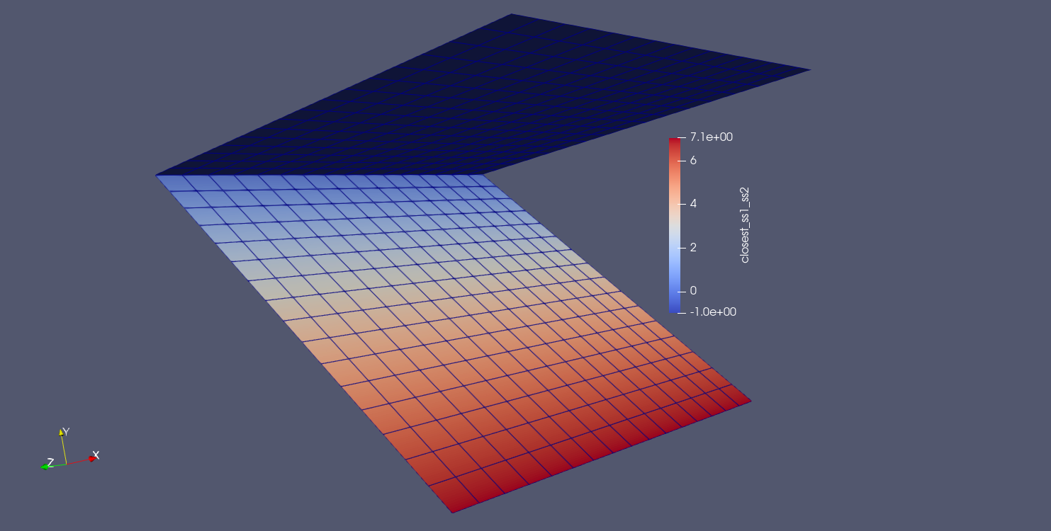
Fig. 9.23 Result using closest distance algorithm |
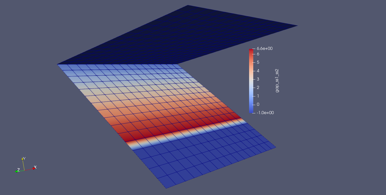
Fig. 9.24 Result using max normal gap algorithm |
Why is this?
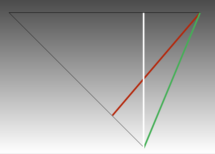
For the closest distance algorithm, we achieve the result shown by the white line. The closet point projection from the bottom surface to the top surface is directly above the node location. This yields a value of 7.071.
For the max normal gap algorithm, we achieve the red result. As can be seen in the figure above, the node normals on the bottom third of the source plate do not intersect with any faces on the target surface (thus, they have a value of -1.0). However, an intersection is found for nodes approximately 1/3 of the way up the source surface, and this is the value used for the max gap. This yields a value of 6.629.
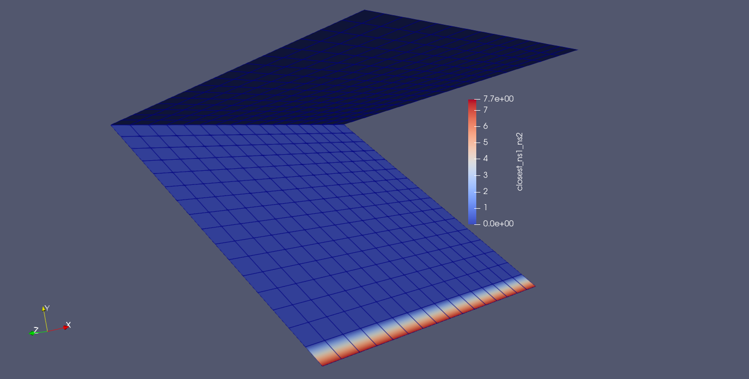
In order to achieve the desired QOI for this problem, the closest distance QOI must be computed either between the bottom surface and a nodeset on the front edge of the top surface or between a nodeset on the front edge of the bottom surface and the nodeset on the front edge of the top surface. This yields the correct value of 7.654.
BEGIN USER OUTPUT
  surface = surface_1
  COMPUTE NODAL closest_ss1_ns2 AS CLOSEST DISTANCE TO nodelist_2
END
Note that when computing from surface to nodeset, we get larger gap values than expected as we move up the bottom surface.
BEGIN USER OUTPUT
  nodeset = nodelist_1
  COMPUTE NODAL closest_ns1_ns2 AS CLOSEST DISTANCE TO nodelist_2
END