8.4. Defining the Contact Surfaces
The user must provide a description of which surfaces will be considered for contact. There are many options available to either automatically detect and create contact surfaces or fine tune specific contact surface definitions.
Many separate contact surfaces can be defined by the analysis. Each contact surface can contain one or more of the following:
The contact surface can include the exterior faces or “skin” of a block of finite elements. An exterior face is an outward facing finite element face that is not sandwiched between two contiguous finite elements. For more information on blocks skinning algorithms see Section 8.4.8.1.
The contact surface can include a set of faces defined as a sideset on the input mesh. All faces included in the face set are considered for contact even if those faces are not exterior faces of the finite elements.
The contact surface can include a set of nodes defined by a node set, surface, block, or assembly of blocks, surfaces, or node set on the input mesh. These nodes need not be attached to finite element faces. The nodes could for example be the nodes of beam elements or particle elements.
The contact surface can be a lofted set of faces around structural or lower dimensional elements. For example contact can define a lofted brick around a two dimensional shell element, a lofted prism around a one dimensional beam element, or lofted sphere around a zero dimensional particle element.
The contact surface can be defined by an analytic function. More information on this capability can be found in the Sierra/SM Capabilities in Development manual.
8.4.1. Contact Surface Command Line
CONTACT SURFACE <string>name CONTAINS <string list>surface_names
This command line identifies a set of sidesets, element blocks, and assemblies of element blocks or surfaces considered as a single contact surface; the string name is the unique name given to this contact surface. The list denoted by surfaces_names is a list of strings identifying surfaces, blocks, and assemblies of blocks or surfaces that are to be associated with this contact surface. The surfaces can be side sets, element blocks, assemblies of blocks, or assemblies of surfaces or any combination of the four as defined in the mesh file.
Any specified element blocks in the surface_names list, or contained in the listed assemblies, that are solid elements (bricks, tetrahedra, wedges, etc.) are “skinned,” meaning that a surface is created from all exterior faces of that element block. See Section 8.4.8.1 for more information on block skinning.
For element blocks in the surface_names list, including those in assemblies, that are lower dimensional (shells, beams, and particles), a lofted geometry is created for use with contact enforcement.
The name you create for a surface can be referenced in command blocks that specify how that surface will interact with other contact surfaces or interact when that surface contacts itself. See Section 8.6.1.2 and Section 8.6.2.1.
The surfaces can contain heterogeneous combinations of finite element faces and lofted geometry.
Warning
A given finite element face or lofted element can be placed in at most one contact surface. See Section 8.4.6 for more information on what happens if different contact surfaces try to include the same mesh objects.
8.4.2. Contact Node Set Command Line
CONTACT NODE SET <string>surface_name
  CONTAINS <string list>nodelist_names
The CONTACT NODE SET command line creates a contact surface named surface_name that contains a set of nodes. The list denoted by nodelist_names is a list of strings identifying node sets, surfaces, blocks, and assemblies of node sets, surfaces, or blocks that are to be associated with the contact node set surface_name. All nodes present in the listed node sets, surfaces, blocks, or assemblies of node sets, surfaces, or blocks will be added to the contact node set. The created node set contains only the mesh nodes of surfaces or blocks, not the faces, and not any lofted geometry. Thus, the contact node set can be used only in a node to face interaction.
8.4.3. Contact Surface Command Block
BEGIN CONTACT SURFACE <string>name
  INCLUDE ALL BLOCKS
  BLOCK = <string list>block_names
  ELEMENT = <int list>elem_numbers
  SURFACE = <string list>surface_names
  ASSEMBLY = <string list>assembly_names
  REMOVE BLOCK = <string list>block_names
  REMOVE SURFACE = <string list>surface_names
  SUBSET <string>subname WITH NORMAL <real> <real> <real>
END [CONTACT SURFACE <string>name]
The CONTACT SURFACE command block can be used to define a contact surface consisting of a more complex collection of finite element faces than can be defined using the CONTACT SURFACE command line.
A surface named name that is a set of faces or lofted elements can be defined by a combination of the command lines INCLUDE ALL BLOCKS, BLOCK, SURFACE, ELEMENT, ASSEMBLY, REMOVE BLOCK, and REMOVE SURFACE. Blocks listed in the block_names list or via ASSEMBLY or INCLUDE ALL BLOCKS will be skinned for exterior faces if the block contains solid elements (like hexahedra, tetrahedra, or wedges.) For blocks that contain shells, beams, or particles, the lofted geometry around those shells beams and particles will be included in the contact surface. The ELEMENT command can be used to pull individual lofted elements into the contact surface by element id.
If a BLOCK command line and a SURFACE command line are both specified within the same CONTACT SURFACE command block, the contact surface created will be the union of the faces in the skin of the blocks and the faces in the specified surfaces in the mesh file.
The contact surface created by the CONTACT SURFACE command block must be either a set of faces and lofted geometry.
Contact surfaces may not be empty. At least one block, element, surface, or assembly must be defined in the input.
Warning
Nodesets and blocks that only contain particles are not available when using CONTACT SURFACE.
8.4.4. Contact Surface Restriction
RESTRICT CONTACT TO SUBDOMAIN DEFINED BY RADIUS <real> AND POINT <real> <real> <real>
For convenience, contact surfaces may be setup via the above contact restriction line command. This line command is usually used in combination with the SKIN ALL BLOCKS command, but it can be used with any contact surface definition commands. When this option is used, contact is restricted to just the nodes/faces within the sphere defined by the RADIUS and POINT specifications. This can drastically improve the performance of skin all blocks in combination with general contact/self contact if you are only interested in having contact active in a particular location in your model.
8.4.4.1. Surface Subsetting
SUBSET <string>subname WITH NORMAL <real> <real> <real>
A contact surface can optionally be subdivided into multiple sub-surfaces based on the surface normal. This command will create a new surface that contains the faces mostly aligned with the specified normal direction. Faces for which the dot product of the unitized face normal vector and the unitized specified normal is greater than 0.45 are placed in the new surface. All other faces are left in the original surface. For example, the following command:
BEGIN CONTACT SURFACE surf1
  BLOCK = block_1
  SUBSET xp WITH NORMAL  1  0  0
  SUBSET zm WITH NORMAL  0  0 -1
END
will create three contact surfaces. Surface surf1_xp will contain the faces most closely aligned with the positive \(x\)-axis. Surface surf1_zm will contain the faces mostly aligned with the negative \(z\)-axis. Surface surf1 will contain all remaining faces in the skin of block_1.
8.4.4.2. Known Issues
The BEGIN CONTACT SURFACE block may sometimes resolve contact faces differently than the basic SKIN ALL BLOCKS or CONTACT SURFACE command. One potential difference is with interior faces. When using global block skinning, a face sandwiched between two element blocks is not considered for contact. However, when faces are constructed with individual block skins plus or minus side sets, those in-between block faces are constructed as contact faces but are ignored.
8.4.5. Skin All Blocks Command
SKIN ALL BLOCKS = <string>ON|OFF(OFF)
  [EXCLUDE <string list>block_names | assembly_names]
The SKIN ALL BLOCKS command provides a convenient way to create a number of contact surfaces covering the exterior skin or lofted geometry of all or most of the element blocks in the analysis. This command may create many surfaces, where the name of each surface is the same as the element block it was generated from. The optional EXCLUDE keyword can be used to skin all element blocks except the listed blocks or assemblies of blocks. For more information on how block skinning works see Section 8.4.8.1
The SKIN ALL BLOCKS is useful for large models in which individual specifying each contact surfaces would be unwieldy. The behavior of skin all blocks is best described by example. If a finite element analysis contains five element blocks:
block_1(eight-noded hexahedral elements)block_3(tetrahedral elements)block_4(shell elements)block_5(beam elements)
The command:
SKIN ALL BLOCKS = ON EXCLUDE block_2
Would be equivalent to defining several independent surfaces with:
CONTACT SURFACE block_1 CONTAINS block_1
CONTACT SURFACE block_3 CONTAINS block_3
CONTACT SURFACE block_4 CONTAINS block_4
CONTACT SURFACE block_5 CONTAINS block_5
The generated contact surfaces would be named block_1, block_3, block_4, and block_5. The contact surfaces named block_1 and block_3 would contain the exterior faces of the solid element blocks block_1 and block_3, respectively. The contact surfaces named block_4 and block_5 would contain lofted geometry around the shell and beam elements in block_4 and block_5, respectively.
The SKIN ALL BLOCKS command can be combined with any of the other surface definition methods available in the CONTACT DEFINITION command block. Generated contact surfaces are assigned based on the order in which these commands are specified. See Section 8.4.8.6 for an example.
8.4.6. Faces and Nodes in Multiple Contact Surfaces
The contact enforcement algorithms in Sierra/SM only allow for a face, node, or lofted object to be associated with a single contact surface. If such a contact entity were allowed to belong to more than one contact surface, ambiguities would arise in determining the interaction properties for that entity.
A situation where an entity could potentially be placed in more than one contact surface is when overlapping sidesets are used in contact. This could also occur if a combination of skinned block surfaces, side sets, and node sets on the mesh file are used to define a contact surface. The side sets can potentially include the same finite element faces as the block skin.
If a given finite element face or node is potentially part of more than one contact surface, then that face or node is included in the first contact surface to which it belongs that is listed in the CONTACT DEFINITION block. If the same face or node also potentially belongs to another contact surface listed later in the CONTACT DEFINITION block, it will not be included again in this later contact surface. A warning message is generated in the log file for any potentially ambiguous cases.
Use of overlapping contact surfaces can be used to implement more advanced behavior such as surfaces tied together at local patches.
The behavior described above is best illustrated by the following examples.
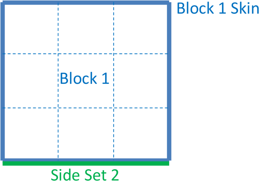
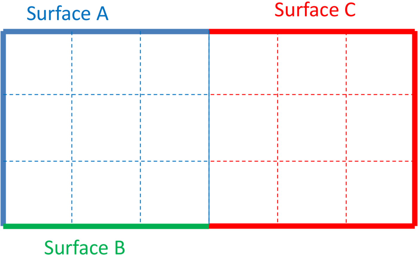
Example 1: Consider the model setup shown in Fig. 8.2(a) In the contact definition block, the contact surfaces are defined by the following input commands:
contact surface surfB contains surface_2
contact surface surfA contains block_1
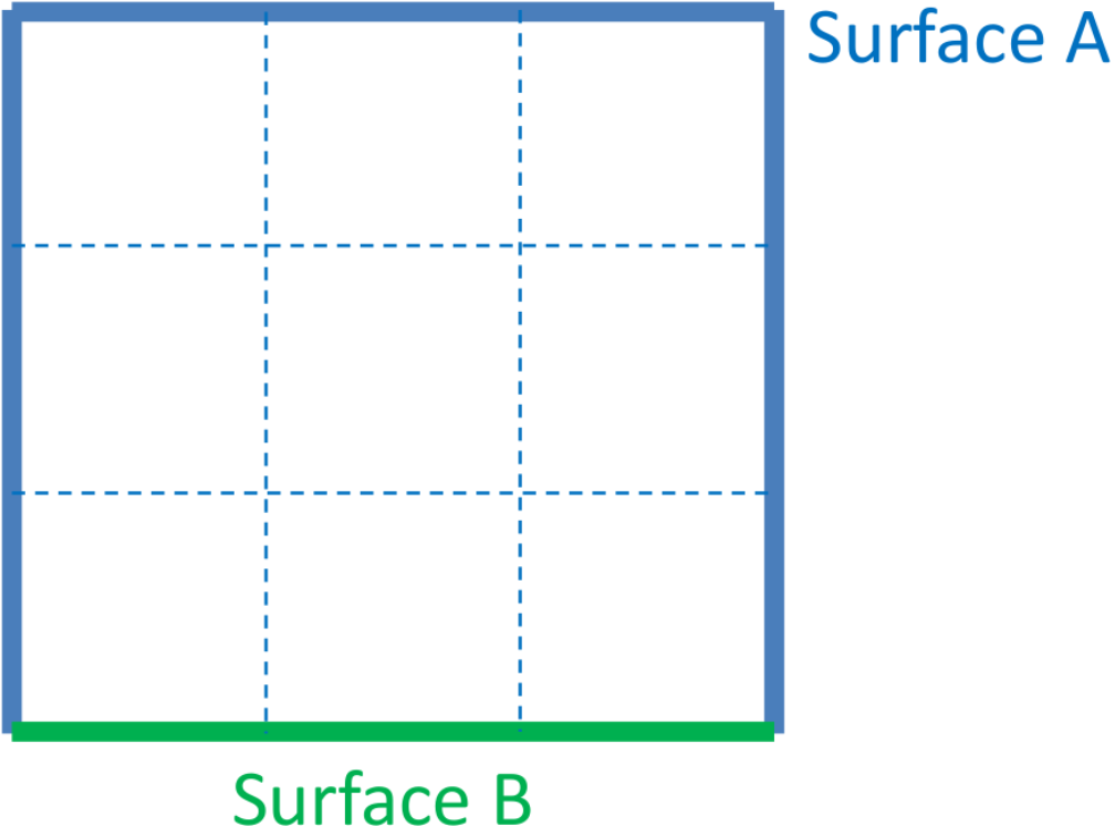
This results in a set of surfaces as shown in Fig. 8.2(b). The contact surface surfB is listed first in the input deck. The faces on side set 2 are placed into surfB, as surfA is listed second in the input deck. The remaining faces on the skin are placed in surfA. This means that the faces that are in both surface_2 and in block_1 are only placed in surfB. The sub-setting mechanism shown in this example may be used to specify a different friction model, such as tied contact, on a small piece of a larger part.
 (a) Setup.
 (b) Results.
Fig. 8.2 Faces in Multiple Contact Surfaces: Example 1.
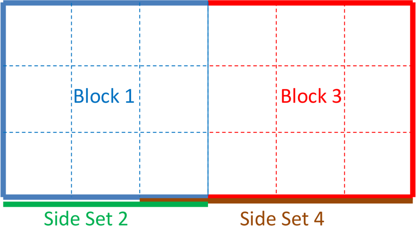
Example 2: A more complex example is shown in Fig. 8.3(a). Consider the following two contact surface definitions:
Contact surface definition 1:
contact surface surfD contains surface_4
contact surface surfB contains surface_2
contact surface surfA contains block_1
contact surface surfC contains block_2
Contact surface definition 2:
contact surface surfB contains surface_2
contact surface surfA contains block_1
contact surface surfC contains block_2
contact surface surfD contains surface_4
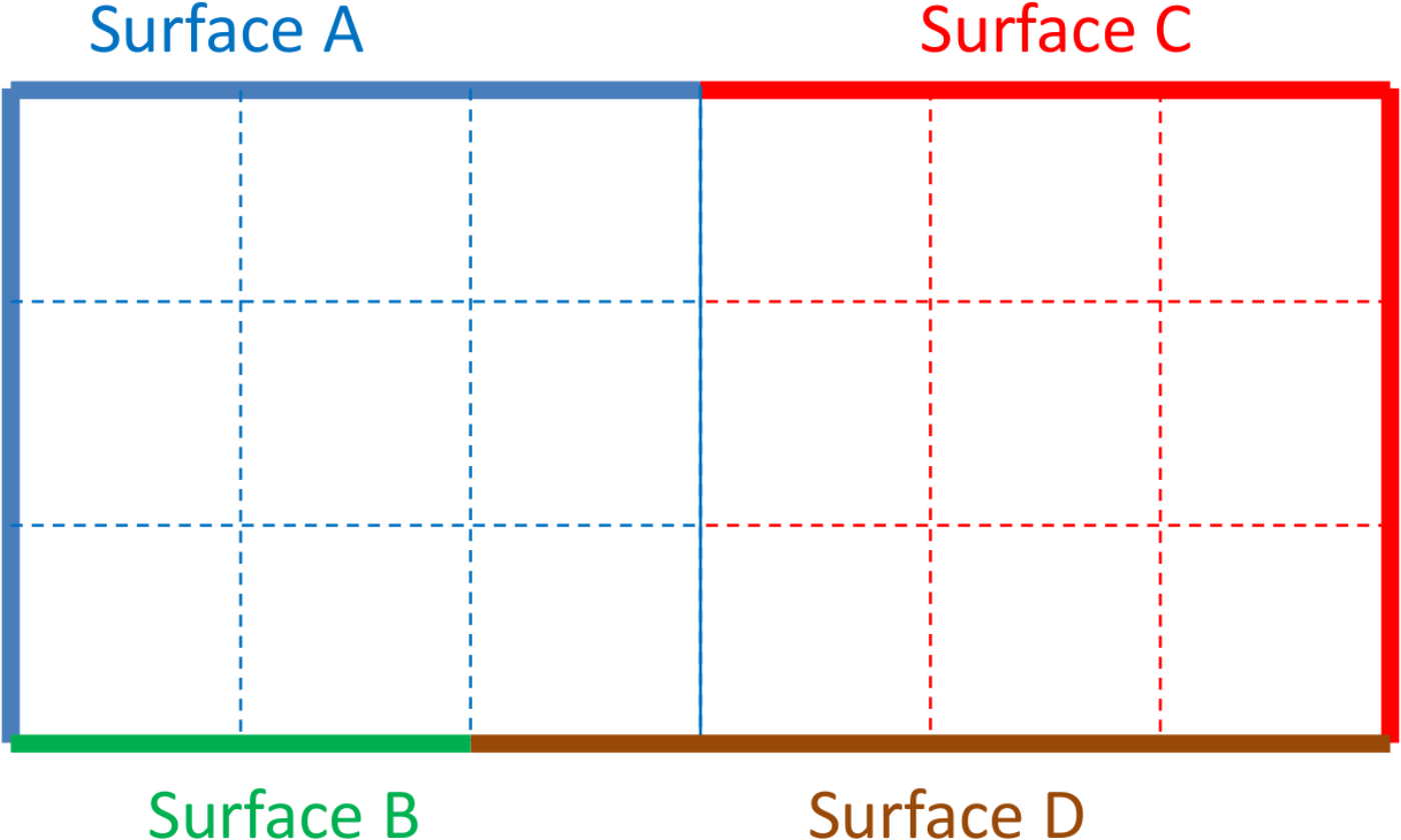
The first contact definition results in the organization of surfaces, as shown in Fig. 8.3(b). The second contact definition results in a different organization of the contact surfaces, as show in Fig. 8.3(c).
 (a) Setup.
 (b) Results 1.
 (c) Results 2.
Fig. 8.3 Faces in Multiple Contact Surfaces: Example 2.
Unlike most commands, the order in which the contact surface definition commands are placed in the input deck may change the analysis behavior. One final note, contact surface definition two above would also be equivalent to the following:
contact surface surfB contains surface_2
skin all blocks = on
contact surface surfD contains surface_4
If the skin all blocks command is present, that command is equivalent to specifying contact on all blocks individually.
8.4.7. Element Death and Surface Updates
When elements are killed in an analysis, contact surfaces may need to be updated to account for the removal of faces attached to killed elements or the addition of faces exposed by element death. The updates happen automatically when elements in a skinned block are removed due to element death (See Section 6.5). The update of these surfaces requires a full re-initialization of contact. Thus, surface-physics models that involve state data may lose some information when the new contact surfaces are created. If contact surfaces are defined by side sets rather than by block skinning, element death will cause the facets attached to killed elements to be removed from the contact surface, but no new facets will be added.
8.4.8. Block Skinning and Surface Definition Examples
A surface is defined as a collection of finite element faces, nodes, and lofted geometry. For a continuum element, any face that is not shared with another element can be considered for contact. A shell element has both a top face and a bottom face. Top, bottom, and side surfaces of shells are automatically created by the contact algorithm and may be lofted by a user-specified thickness. Contact is enforced on shells by computing the contact forces on the top and bottom surfaces of the shells and then moving the resulting forces back to the original shell nodes.
The easiest method to create contact surfaces is by skinning blocks. Block skinning identifies the exterior surfaces of a block and puts them in a contact surface. The following examples demonstrate how block skinning works in various circumstances.
8.4.8.1. Simple Block Skinning
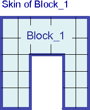
Fig. 8.4 Simple block skinning example.
See Fig. 8.4. This first example is a single block being skinned. This skinning could occur by one of the input lines
CONTACT SURFACE block_1 CONTAINS block_1
or if the model contains only block_1
SKIN ALL BLOCKS = ON
For either syntax all the exterior facets of block_1 are automatically identified and are placed into a contact surface which is also named block_1.
8.4.8.2. Block Skinning With Multiple Element Blocks
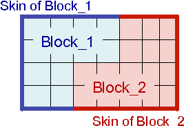
Fig. 8.5 Block skinning with multiple blocks example.
Fig. 8.5 shows an example of two blocks that are equivalenced on their interface. An equivalenced interface means that the two blocks share nodes at the interface so that there are no exposed contact faces between block_1 and block_2. The syntax to create the contact surfaces shown in Fig. 8.5 is:
CONTACT SURFACE block_1 CONTAINS block_1
CONTACT SURFACE block_2 CONTAINS block_2
Alternatively, if the model contains only block_1 and block_2, this could be accomplished by requesting that all blocks be skinned:
SKIN ALL BLOCKS = ON
For either syntax, all the exterior facets that are connected to elements that are part of block_1 are placed in contact surface block_1. All the exterior facets that are connected to elements of block_2 are placed in contact surface block_2. Any interior facet (one that is sandwiched between two elements) is not placed in any contact surface.
8.4.8.3. More Complex Block Skinning Cases
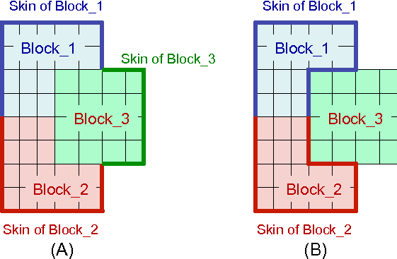
Fig. 8.6 Block skinning advanced example.
Block skinning considers only those elements actually present in the contact definition when deciding if a face is exposed. The surfaces shown by heavy lines in Fig. 8.6(A) will result from the following syntax:
CONTACT SURFACE block_1 CONTAINS block_1
CONTACT SURFACE block_2 CONTAINS block_2
CONTACT SURFACE block_3 CONTAINS block_3
All the exterior facets of the model have been placed in the contact surfaces associated with elements of the named blocks. Any facet sandwiched between two contact surface blocks is not considered to be on the exterior, and is thus not placed in any contact surface. The surfaces shown in Fig. 8.6(B) will result from the following syntax:
CONTACT SURFACE block_1 CONTAINS block_1
CONTACT SURFACE block_2 CONTAINS block_2
or
SKIN ALL BLOCKS = ON EXCLUDE block_3
In this case, block_3 was not included in the contact definition. Thus the faces on the block_1 block_3 and block_2 and block_3 boundaries will be considered exterior for the purposes of contact. Since block_3 is not part of the contact definition none of the remaining faces of block_3 will be part of any contact surface.
8.4.8.4. Combining Block Skinning, Side Sets, and Element Death
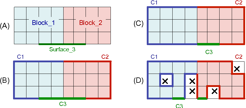
Fig. 8.7 Contact surface definition examples.
Fig. 8.7(A) shows a set of element blocks and surface sidesets as defined in a mesh file. Blocks block_1 and block_2 are equivalenced sharing nodes on their boundary. The surface surface_3 is a sideset defined on part of the exterior of block_1 and block_2. The contact surfaces shown in Fig. 8.7(B) will be generated by the following syntax:
CONTACT SURFACE c3 CONTAINS surface_3
CONTACT SURFACE c1 CONTAINS block_1
CONTACT SURFACE c2 CONTAINS block_2
As described in Section 8.4.6 the first surface defined in the input file that includes a facet owns that facet. If any subsequently defined contact surfaces attempt to include a facet that already belongs to a contact surface, it will be left in the original contact surface that it belongs to, and will not be made part of the surface that is defined later in the input file. In other words, a given mesh facet can belong in at most one contact surface, and when a conflict arises, the facet will belong to the first contact surface in the input file that included it. Thus, c3 contains the facets associated with surface_3. Contact surfaces c1 and c2 do not contain any of the facets of side set surface_3.
The surfaces in Fig. 8.7(C) are be generated by the following syntax:
CONTACT SURFACE c1 CONTAINS block_1
CONTACT SURFACE c3 CONTAINS surface_3
CONTACT SURFACE c2 CONTAINS block_2
Since contact surface c1 is listed before contact surface c3 in the input file, c1, the skin of block_1, contains the contact facets that could have been part of c1 or c3. Since contact surface c3 is listed before contact surface c2 in the input file, contact surface c3 includes the remaining portions of surface_3, while c2, the skin of block_2, contains only the remaining exterior facets of block_2.
When element death occurs, new contact facets may be exposed and old contact facets may be deleted. After element death, the ownership of contact facets in the updated contact surfaces will be evaluated as if the dead elements never existed. Fig. 8.7(D) shows the effect of element death on the contact surfaces. For this case the contact surfaces are defined by the same syntax as the case shown in Fig. 8.7(B):
CONTACT SURFACE c3 CONTAINS surface_3
CONTACT SURFACE c1 CONTAINS block_1
CONTACT SURFACE c2 CONTAINS block_2
Elements shown in the figure with an X are dead elements. Any newly exposed facets of block_1 and block_2 are added to the relevant contact surfaces. If all the elements attached to contact facet are deleted, the contact facet itself is also deleted. If a contact surface is defined via a side set, that surface can only lose faces. In other words, a contact surface defined by a contact side set cannot gain any faces that were not part of the original side set during the process of element death.
8.4.8.5. Equivalenced Solid and Shell Meshes
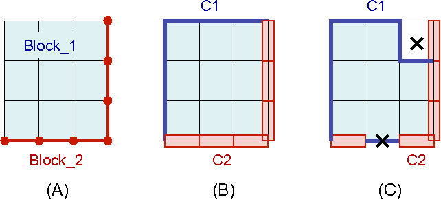
Fig. 8.8 Hexahedral and shell contact surface definitions.
A mesh that includes both solid elements such as hexahedral and shell elements obeys some special rules when defining contact surfaces via block skinning. Fig. 8.8(A) shows block_1, (solid hexahedral elements) and block_2 (quadrilateral shell elements). The nodes of the shell element block are equivalenced with the nodes of the hexahedral element block, or in other words, the two blocks share nodes on their interface. Fig. 8.8(B) shows the contact surfaces that would be generated using the following commands:
CONTACT SURFACE c1 CONTAINS block_1
CONTACT SURFACE c2 CONTAINS block_2
No matter what the order of the contact surfaces in the input file is, the shell block will always be considered “outside” the solid element block for this case. On portions of block_1 without any cladding shells, the standard block skinning rules apply. On the interface between block_1 and block_2 the quad faces on the block_1 hexahedral elements are considered sandwiched between the block_1 hexahedral elements and the block_2 shell elements. Thus, c1 contains none of the interface facets. Contact surface c2 contains the lofted shell geometry associated with the shell elements of block_2.
In Fig. 8.8(C), some elements have been removed due to element death. As in the example in Section 8.4.8.4, when elements are killed via element death the contact surfaces are reevaluated as if those elements were never there. When a cladding shell is removed the exterior face of block_1 is exposed and joins contact surface c1. The death of one of the lofted shell elements removes all faces associated with that element’s lofted geometry.
8.4.8.6. Skin All Blocks with Contact Surface Definition
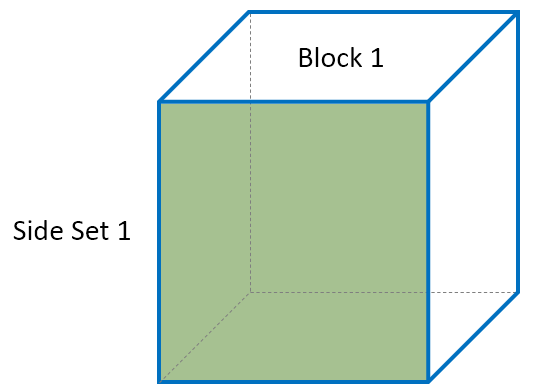
Fig. 8.9 Skin all blocks with contact surface definition example.
SKIN ALL BLOCKS = ON
CONTACT SURFACE surf_1 CONTAINS surface_1
If SKIN ALL BLOCKS is specified before any contact surface definition, the generated contact surfaces are assigned to the blocks’ exterior skin and the surfaces specified in the contact surface definitions will likely not have any faces. Thus, in this example, block_1 will have all 6 faces and surf_1 will not receive any faces. This will generate a warning to alert the user.
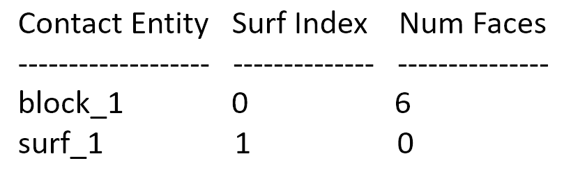
Fig. 8.10 Abbreviated table from log file for skin all blocks before contact surface definition, showing that block_1 gets all 6 faces assigned to it, and surf_1 does not receive any faces.
CONTACT SURFACE surf_1 CONTAINS surface_1
SKIN ALL BLOCKS = ON
Conversely, if the SKIN ALL BLOCKS command is specified after the contact surface definition, the exterior skin will only be assigned any remaining contact surfaces once they are assigned based on the contact surface definitions. In this example, the one face on side set 2 is first assigned to surf_1. Then, the remaining 5 faces are assigned to block_1.
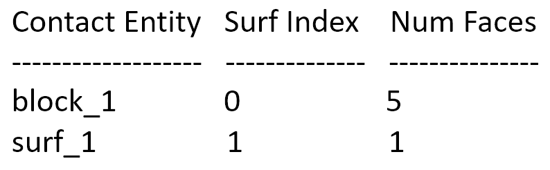
Fig. 8.11 Abbreviated table from log file for skin all blocks after contact surface definition, showing that block_1 gets assigned 5 faces, while surf_1 is assigned 1 face.