8.12. Examples
This section has several example problems. The geometric configuration for each problem is presented together with a brief description and the appropriate command lines.
8.12.1. Example 1
The first example problem has two blocks that come into contact due to initial velocity conditions. Block 1 has an initial velocity equal to \(v1\), and block 2 has an initial velocity equal to \(v2\). The geometric configuration for this problem is shown in Fig. 8.26.
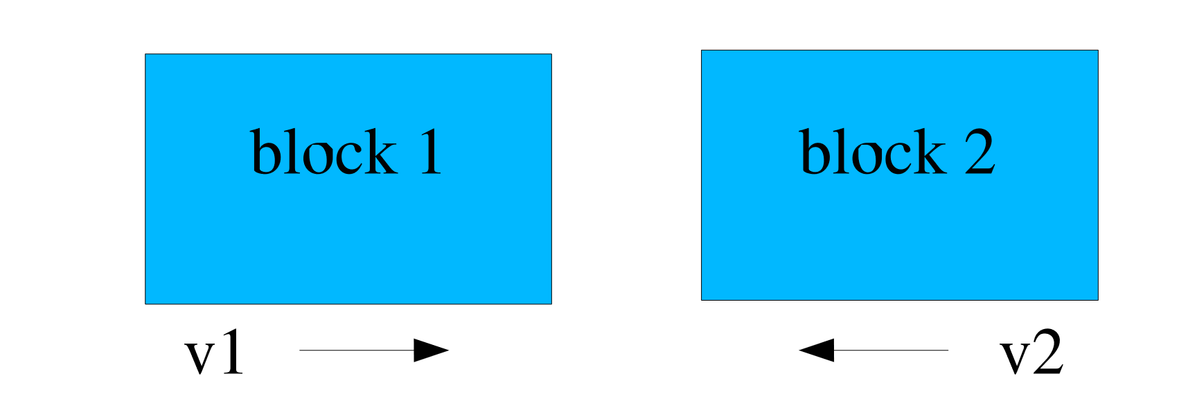
Fig. 8.26 Problem with two blocks coming into contact.
The simplest input for this problem will be named EXAMPLE1 and is shown as follows:
BEGIN CONTACT DEFINITION EXAMPLE1
  #
  # define contact surfaces
  SKIN ALL BLOCKS = ON

  # set interactions
  BEGIN INTERACTION DEFAULTS
    GENERAL CONTACT = ON
  END

END
In this example, the SKIN ALL BLOCKS command line with parameter set to ON will create a surface named block_1 from the exterior skin of block_1 and a surface named block_2 from the exterior skin of block_2. The GENERAL CONTACT = ON command defines that block_1 can contact block_2. As no friction model was specified, the default frictionless model is used for this interaction.
Now consider the same problem (two blocks coming into contact) in which it is desired that the two blocks interact with a coulomb friction model. The input for this variation of the two block problem will be named EXAMPLE1A and is shown as follows:
BEGIN CONTACT DEFINITION EXAMPLE1A
  #
  # define contact surfaces
  SKIN ALL BLOCKS = ON

  # friction model definition
  BEGIN CONSTANT FRICTION MODEL rough
    FRICTION COEFFICIENT = 0.5
  END

  # set interactions
  BEGIN INTERACTION EX1A
    SURFACES = block_1 block_2
    FRICTION MODEL = rough
  END
END
As was the case for the EXAMPLE1 command block, the SKIN ALL BLOCKS command line with its parameter set to ON will create a surface named block_1 from the skin of block_1 and a surface named block_2 from the skinning of block_2.
In order to have frictional contact between the two blocks, a constant Coulomb friction model is specified with a CONSTANT FRICTION MODEL command block. We name this model ROUGH and specify the coefficient of friction as 0.5.
In the INTERACTION command block, the friction model ROUGH is selected on the FRICTION MODEL command line. This model is then applied to the interaction of surfaces block_1 and block_2.
8.12.2. Example 2
A second more complex example problem has three blocks that come into contact due to initial velocity conditions. Block 1 is a solid element brick block with initial velocity equal to \(v1\). Block 3 is a solid element brick block with initial velocity \(v3\). Block 2 is a shell element block that has zero initial velocity. There is a side set (Surface 3) on the top faces of block 3. The geometric configuration for this problem is shown in Fig. 8.27.
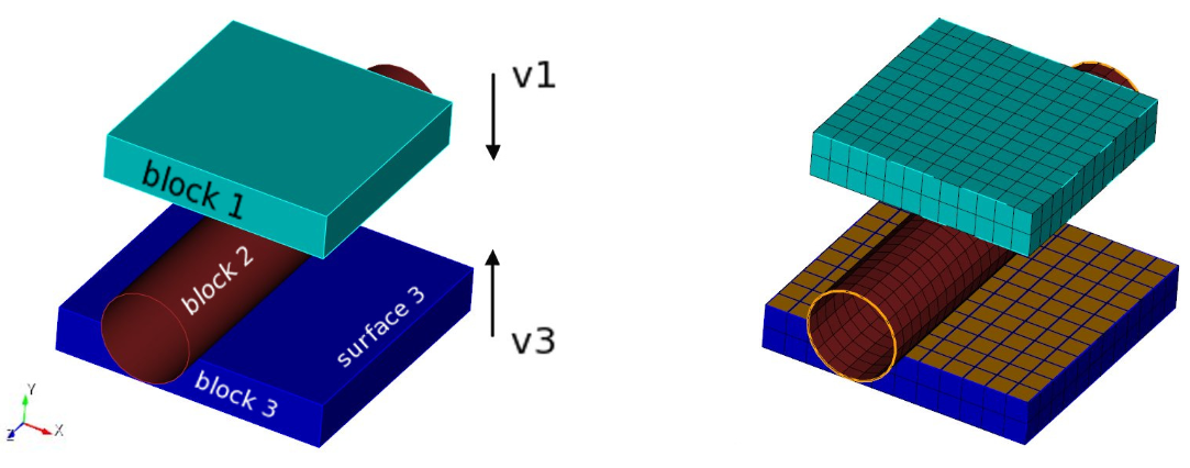
Fig. 8.27 Problem with three blocks coming into contact.
The contact input for this three-block problem is called EXAMPLE2 and is shown as follows:
BEGIN CONTACT DEFINITION EXAMPLE2
  #
  # define contact surfaces
  CONTACT SURFACE b1 CONTAINS block_1
  CONTACT SURFACE b2 CONTAINS block_2
  CONTACT SURFACE s3 CONTAINS surface_3

  BEGIN CONSTANT FRICTION MODEL rough
    FRICTION COEFFICIENT = 0.5
  END
  #
  # set interactions
  BEGIN INTERACTION DEFAULTS
    FRICTION MODEL = rough
    GENERAL CONTACT = ON
    SELF CONTACT = ON
  END

  # set specific interaction
  BEGIN INTERACTION
    SURFACES = b2 s3
    FRICTION MODEL = FRICTIONLESS
  END

END
In the EXAMPLE2 command block, three surfaces have been defined. The first surface, b1, is obtained by skinning block_1. The second surface, b2 is obtained by skinning block_2. The third surface, s3, is the user-defined side set surface_3.
In the INTERACTION DEFAULTS command block, we select the friction model ROUGH on the FRICTION MODEL command line. Both GENERAL CONTACT and SELF CONTACT are set to ON. For this problem the hollow cylinder, block_2, will undergo self-contact. Setting GENERAL CONTACT to ON will enforce contact between b1 and b2, b2 and s3, and b1 and s3. Setting SELF CONTACT to ON will enable self-contact for all three of the surfaces.
For this particular example, we want to override some of the default setting for surface interactions which were previously set by the INTERACTION DEFAULTS command block. The INTERACTION command block shown in EXAMPLE2 overrides these defaults and instead specifies surfaces b2 and s3 to have a frictionless interaction.
In Fig. 8.28, the bodies are shown after deformation and contact. The second image shows a cross section cut through the center. Due to the lofting of the shell surface there is a small gap between the shell elements themselves and the compressing blocks, which is expected. The actual contact geometry is shown in Fig. 8.29. Note that as block_1 is skinned, the entire exterior surface of block_1 is included in contact surface b1. The lofted geometry of the shell blocks is seen in this figure, this lofted geometry is both contacting with the blocks and experiencing self contact. Contact surface s3 contains only the top sideset on block_3, not the entire skin.
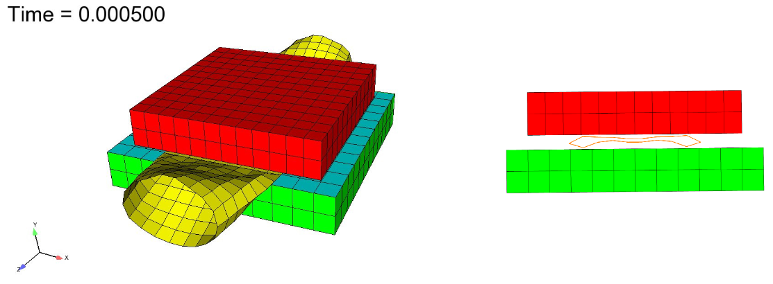
Fig. 8.28 State of bodies after contact and deformation.
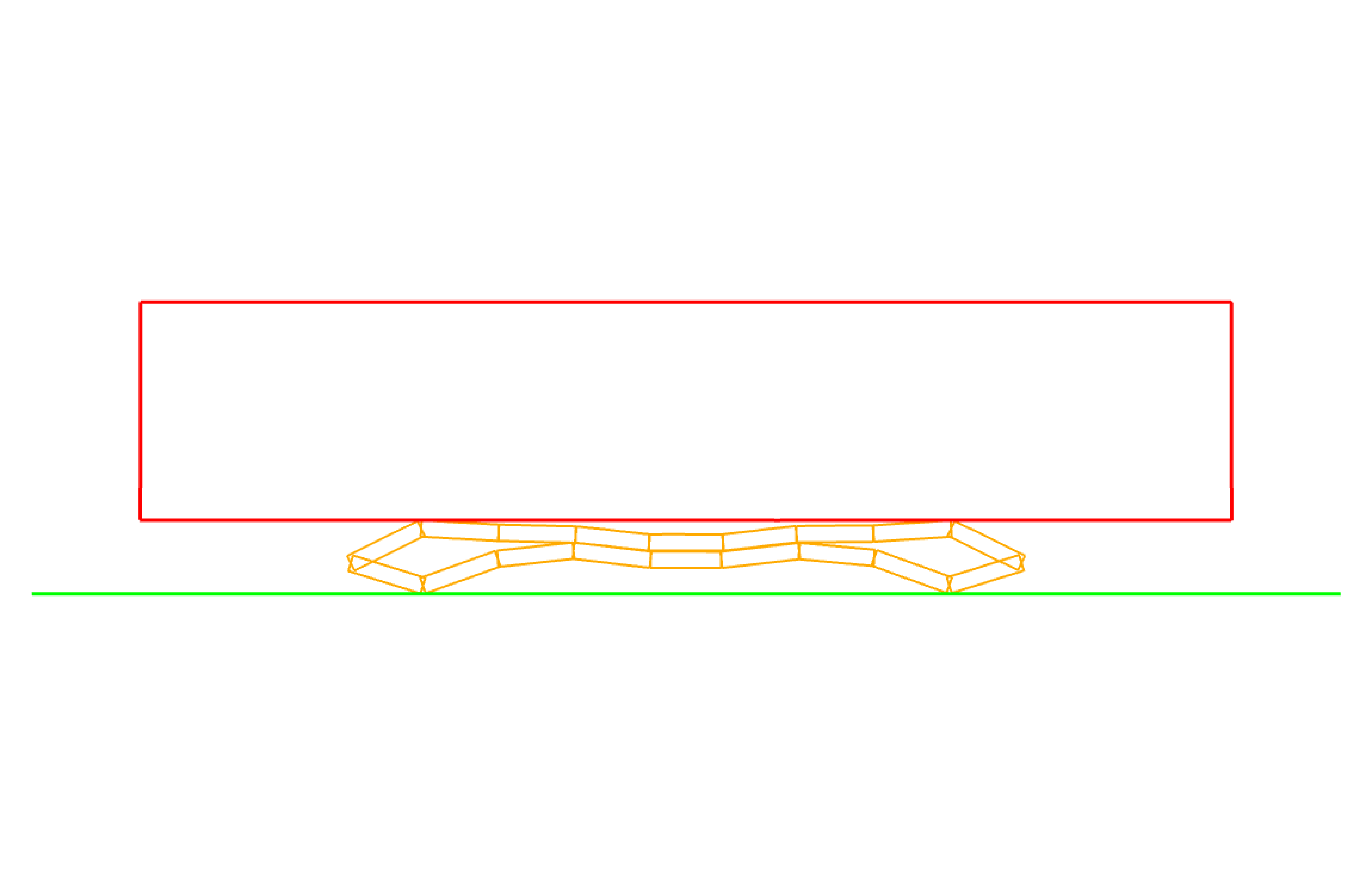
Fig. 8.29 Deformed contact geometry.