Plate with Multiple Holes
Warning
Support for XFEM in Sierra/SM is currently at an experimental level. As such, not all features may be fully implemented or tested and the analyst should use this capability with caution.
Product: Sierra/SolidMechanics - Explicit Analysis
Problem Description
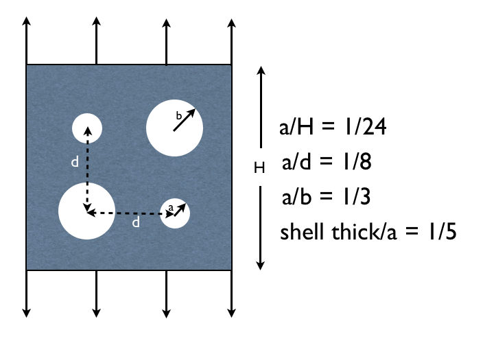
Fig. 68 Plate with multiple holes problem set-up.
The purpose of the following numerical examples is to display the X-FEM nucleation and branching capabilities for 2-D shell elements. Consider a plate with a multiple holes under uniform tensile loading (Fig. 68). As the force increases as the top and bottom are pulled apart, a stress concentration forms at the sides of both large holes. Once the stress concentration reaches the fracture stress, a crack nucleates at these locations. The cracks grow in multiple different modes, and the cracks branch when their user specified branching criteria is reached.
Loading and Boundary Conditions
A force is applied to the top and bottom of the plate at a linear rate. The nucleation method that was chosen for this problem is element based nucleation and the nucleation and branching failure parameter is maximum principal stress.
Material Model
An elastic-plastic material model is used, and the material properties can be found in Table 18 below.
Metric units are used |
|---|
Displacement: meters |
Mass: kilograms |
Time: seconds |
Force: \(kgm/s^2\) |
Temperature: Kelvin |
Plate with Hole |
||
|---|---|---|
Young’s Modulus: |
E |
\(210\times10^3\) |
Poisson’s Ratio |
\(\nu\) |
0.3 |
Density |
\(\rho\) |
\(7.8\times10^-3\) |
Yield Stress |
\(\sigma _{yield}\) |
360 |
Hardening Modulus |
H |
\(50\times10^3\) |
Beta |
\(\beta\) |
0.75 |
Finite Element Model
The elements that were used for this simulation were Belytschko-Tsay shell elements.
Feature Tested
X-FEM crack nucleation, piecewise-linear crack growth, and crack branching in shells under dynamic conditions.
Results and Discussion
As can be seen in Fig. 69 below, the stress concentration just before crack nucleation is the highest around the 2 large holes. Once crack nucleation is initiated, stress waves propagate throughout the geometry as shown in Fig. 70. The cracks propagate in multiple different fashions, with other cracks nucleating in the geometry as well as crack branching occurring (Fig. 71).
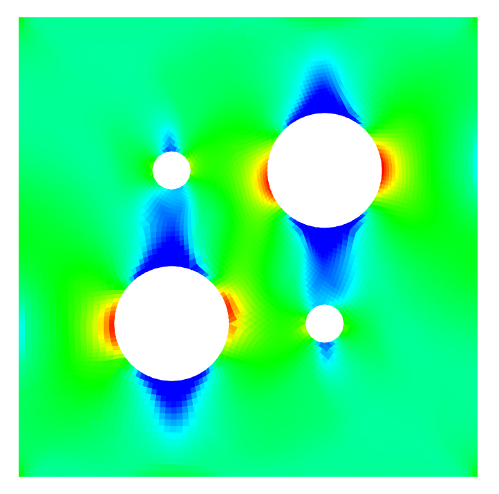
Fig. 69 Multi holes before nucleation. |
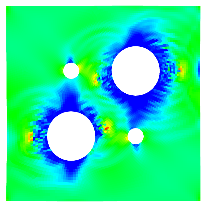
Fig. 70 Stress waves after nucleation. |
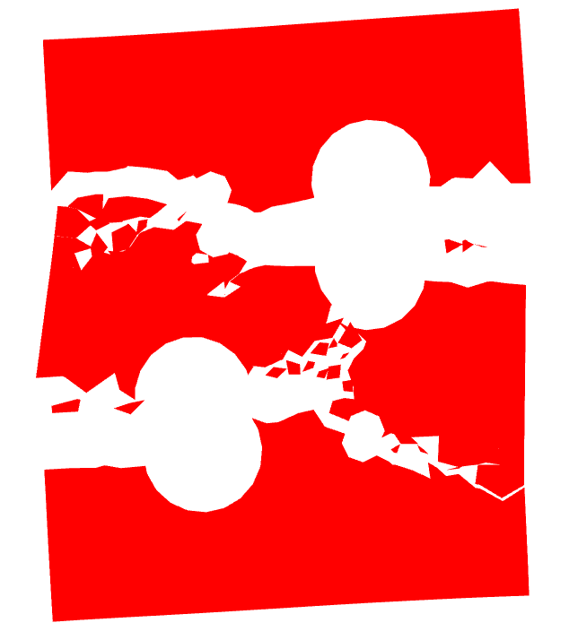
Fig. 71 Plate with Multiple Holes Snapshots.