Angled Crack Cylinder
Warning
Support for XFEM in Sierra/SM is currently at an experimental level. As such, not all features may be fully implemented or tested and the analyst should use this capability with caution.
Product: Sierra/SolidMechanics - Explicit Analysis
Problem Description
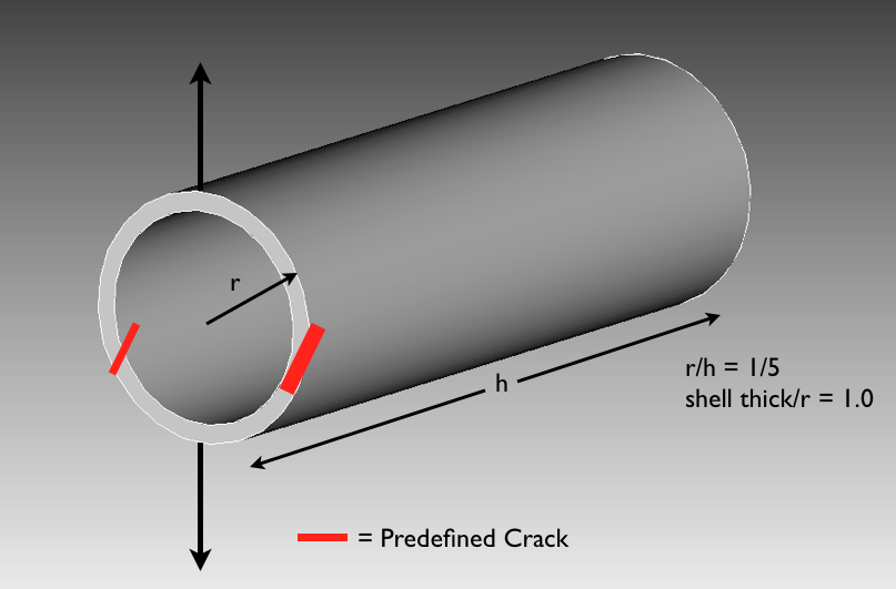
Fig. 65 Angled crack cylinder problem set-up.
The purpose of the following numerical example is to display the X-FEM cutting by prescribed object and planar crack growth capabilities for 2-D shell elements. Consider a hollow cylinder under uniform tensile loading at the rim of the cylinder and an angled prescribed crack (Fig. 65). As the force increases as the top and bottom of the cylinder are pulled apart, a stress concentration forms at the crack tip. Once the stress concentration reaches the crack growth stress, the crack grows across that particular element. This problem is run using explicit dynamics.
Loading and Boundary Conditions
A prescribed displacement is applied to the top and bottom of the rim of the cylinder at a linear rate. The prescribed object used for cutting is a disk whose midpoint is placed at the end of the cylinder, halfway between the center of the cylinder and the bottom rim. The crack growth parameter that was used was chosen for this problem is maximum principal stress.
Material Model
An elastic-plastic material model is used, and the material properties can be found in Table 17 below.
Metric units are used |
|---|
Displacement: meters |
Mass: kilograms |
Time: seconds |
Force: \(kgm/s^2\) |
Temperature: Kelvin |
Cylinder |
||
|---|---|---|
Young’s Modulus: |
E |
\(1.0\times10^9\) |
Poisson’s Ratio |
\(\nu\) |
0.25 |
Density |
\(\rho\) |
\(2.61\times10^-4\) |
Yield Stress |
\(\sigma _{yield}\) |
36,000 |
Hardening Modulus |
H |
0.0 |
Beta |
\(\beta\) |
1.0 |
Finite Element Model
The elements that were used for this simulation were Belytschko-Tsay shell elements.
Feature Tested
X-FEM cut by prescribed object, and planar crack growth.
Results and Discussion
As can be seen in Fig. 66 below, the prescribed crack grows when the user-specified maximum principal stress is reached. The crack propagates up the geometry in a planar fashion, and a sliver of the cylinder is cut off. As the displacement is applied, the geometry separates into two separate pieces. In Fig. 67, the triangles over the geometry are not elements but visualization surfaces; the element used is still the Belytschko-Tsay four node shell.
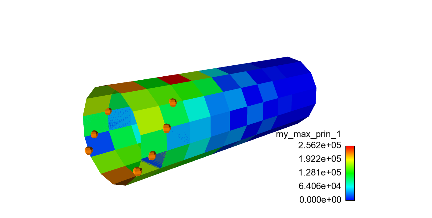
Fig. 66 Planar crack growth
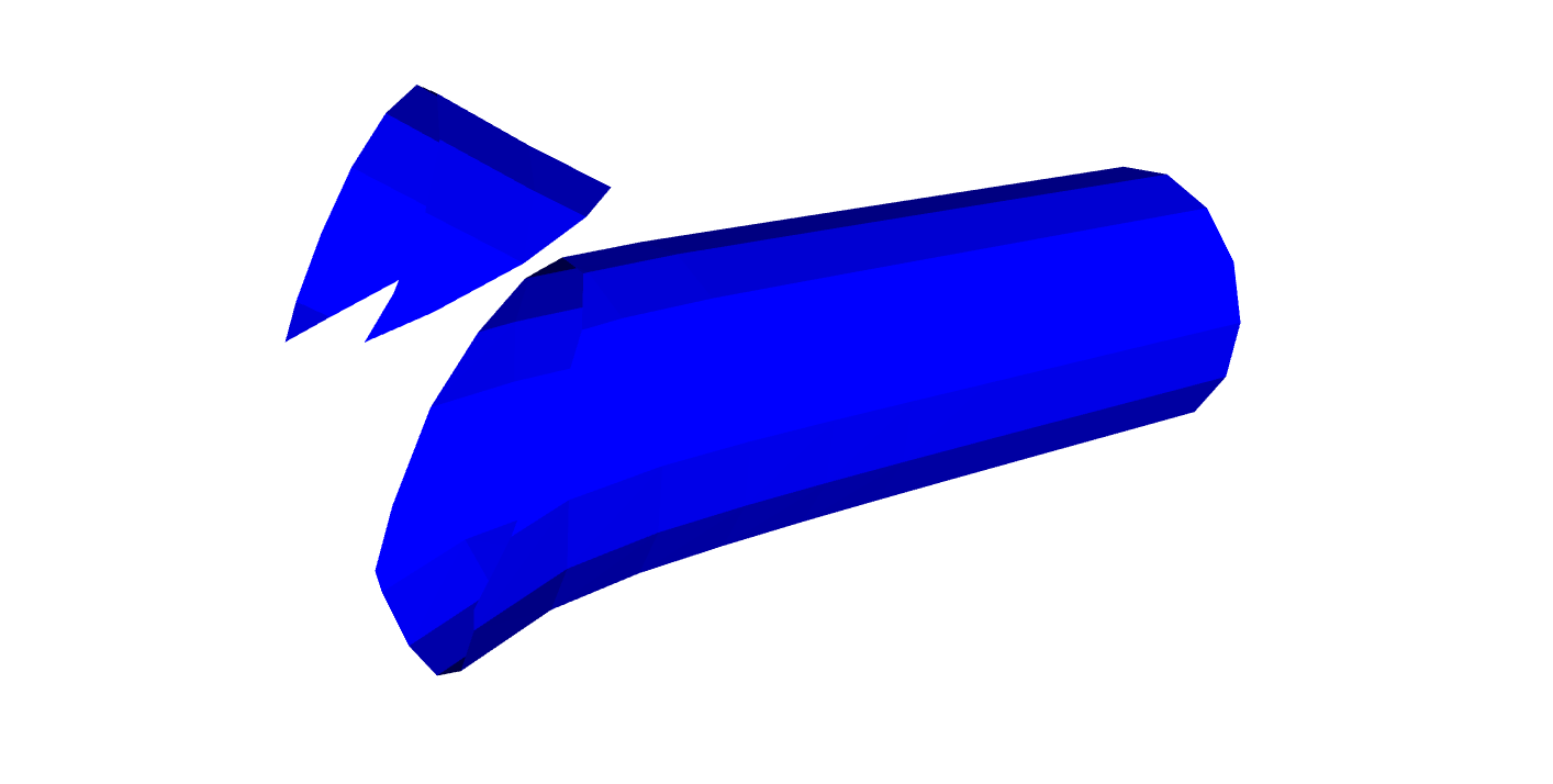
Fig. 67 Piece of cylinder is cut off and separates.