4.4.13. Pressurization Zones
Upon heating, materials like foams or energetic materials can decompose and produce gas that can accumulate in pore spaces and free volumes. A pressurization zone can be used to track the approximate pressure from this gas production using a simple molar balance and equation of state without the need to solve fluid dynamics equations. This pressure may simply be post-processed, or it may influence reaction kinetics for pressure-dependent reaction mechanisms.
Each pressurization zone requires a few pieces of information to be configured:
A list of source blocks (blocks that produce gas)
A list of pressurized blocks and bulk nodes (blocks with void space where gas can be contained)
An equation of state (e.g. ideal gas or BKWS) to use to calculate pressure as a function of temperature, volume, and number of moles of gas
A temperature averaging method (to determine the average temperature to use for the equation of state)
Initial pressure (to determine the initial amount of gas in the zone)
(optional) The volume and temperature of a non-meshed excess domain (e.g. a region where gas could accumulate that is not a part of the Aria model)
For each pressurization zone, a global variable for pressure, temperature, gas volume, and total moles will be created and shown in the log file. These can be output to heartbeat, included in the Exodus file, and used in user functions along with other global variables.
The complete set of commands for the pressurization model can be found in the command summary section.
4.4.13.1. Example
Consider the problem in the image below. Upon heating, the foam block (block_4) could produce gas that would flow into the void spaces in block_4, block_3, and the bulk node air1.
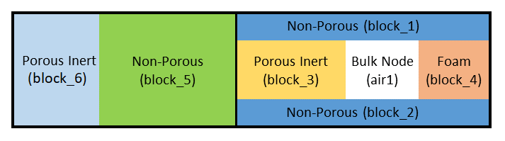
Fig. 4.27 Example domain for pressure zone setup.
To set up a pressurization zone to track the pressure of the gas in that domain, we would add the following pressurization model in the Aria Region, assuming the zone was initially at 14 psi:
Begin Pressurization Model Aft_Cavity
  Equation of State = Ideal_Gas
  Pressure Unit = psi
  Initial Pressure = 14
  Pressurization Source Blocks = block_4
  Pressurized Blocks = block_3 block_4
  Pressurized Bulk Nodes = air1
End
There are some required material properties for blocks involved in the pressurization zone:
In order to calculate the gas volume, all the
Pressurized Blocksmust define a model forvolume fraction gasin their material models.To calculate gas produced, all blocks in
Pressurization Source Blocksmust define aSPECIESexpression for the molar concentration of produced gas (moles/volume) in their material models. This could be defined from a chemistry model, level set state, or a custom user function.If a block has pressure-dependent reactions and needs the pressurization zone pressure, it should define
PRESSURE = PRESSURIZATION_MODELin the material model.
When using a CHEMEQ model, there are pre-defined SPECIES and VOLUME FRACTION GAS models that can be used to calculate these quantities based on the CHEMEQ model state. In the example below, the SPECIES is calculated based on the production of the species marked as “gas” in the CHEMEQ definition, and volume fraction of gas is calculated using the solid_density values and mass fractions of the solids taken from CHEMEQ.
Begin aria material foam # block_4
  Species Names = FOAM CHAR CO2

  Mass_Fraction of FOAM = From_ChemEq
  Mass_Fraction of CHAR = From_ChemEq

  Solid_Density of FOAM = Constant  rho_solid = 1200
  Solid_Density of CHAR = Constant  rho_solid = 1500

  Pressure = Pressurization_Model
  Volume Fraction Gas = From_Chemeq_Mass_Fractions
  Species = ChemEq_Gas

  # ...

  Begin Parameters for Chemeq Model foam_decomp
    species names are             FOAM      CHAR      CO2
    species phases are            Condensed Condensed Gas
    Species molecular weights are 1         1         120  # solid values don't matter here

    # ...

    Concentration Units = Mass Fractions
  End
End

Begin aria material porous_inert # block_3
  volume fraction gas = 0.01

  # ...

End
4.4.13.2. Pressure Unit
The default pressure unit is Pascals (Pa). Other options are psi or atm. The pressure global variable will be in the units specified here, and will have the unit appended to the global variable name (e.g. pZone1_pressure_psi).
4.4.13.3. Temperature Averaging Method
This section describes the different averaging methods that can be selected to get an effective temperature ( ). In all cases,
  is the volume fraction of gas. This effective temperature is used in the equation of state to calculate the pressure in the pressurization zone.
Method |
Effective Temperature |
|---|---|
|
|
|
|
|
|
|
|


The IDEAL_GAS averaging is the most physically accurate method and is the recommended selection for all use-cases. It is the default if the averaging is not specified. It is derived by starting with the following relationships and solving for , assuming the pressure and compressibility (Z) are spatially uniform across the pressurized zone:


4.4.13.4. Equation of State
Given the volume, temperature, and number of moles of gas present in the pressurized zone, an appropriate equation of state is still required to calculate pressure. This is specified in the pressurization model block, and can be one of the options listed below. Any arguments required for the equation of state are given on the same line, after its name. All equations of state have the optional gas constant argument, R, which defaults to 8314 J/kmol-K if omitted. If your molar concentrations (SPECIES) are in units of moles, then you must supply R in J/mol-K (8.314).
4.4.13.4.1. Ideal Gas
The ideal gas equation of state requires no coefficients and evaluates the pressure as

and is specified (with or without R) by
Equation of State = Ideal_Gas R = 8.314
4.4.13.4.2. BKWS
The BKWS equation of state requires one parameter, the co-volume ( ). The values of
  ,
,  , and
, and  are constants (10.5e-3, 0.298, and 6620 respectively). The pressure is then evaluated using:


It is specified (with or without R) by
Equation of State = BKWS covol = VALUE R = 8.314
4.4.13.4.3. Van Der Waal
The VanDerWaal equation of state requires two parameters,  and
and  . The pressure is then evaluated using:

It is specified (with or without R) by
Equation of State = VanDerWaal a = VALUE b = VALUE R = 8.314
4.4.13.5. Venting and Coupling
Aria has some basic capabilities to model venting of a pressurization zone to the environment, as well as to couple the pressure of multiple pressurization zones to one another to allow flow between zones. Venting may be modeled by setting VENTING MODEL = VENTED in the pressurization model block. This also requires specifying a model for the venting flow rate as a function of the pressure in the zone. At present there are 2 supported models, one that accounts for choked flow and one that does not. Both models take the form:

where  is an empirical factor,
  is the density of the gas in the pressurization zone,
  is the pressure in the pressurization zone, and
  is the pressure of the environment the gas is venting to. The choked flow model switches to the form:

once  where
where  is the user-specified critical pressure ratio. The value of can be set using any of the generic material model forms supported by Aria (i.e. constant, polynomial, user function, etc.). A sample vented pressurization zone input deck block is presented below:
Begin Pressurization Model pZone1
  Initial Pressure = 13
  Initial Mixture Molecular Weight = 32
  Pressure Unit = psi

  Pressurization Source Blocks = block_1
  Pressurized Blocks = block_1

  Venting Model = Vented
  Venting Model Property Venting_Volumetric_Flow_Rate = K_FACTOR_WITH_CHOKING \$
      critical_pressure_ratio=2.
  Venting Model Property ambient_pressure = constant value = 13
  Venting Model Property K_factor = constant value=1.e-2

  Equation of State = Ideal_Gas
End Pressurization Model pZone1
Multiple pressurization zones may be connected using the same model forms for the flow rate as are available for venting. This can be used to model multiple sealed volumes connected by a restricted flow path or feature that is initially sealed until it reaches a certain temperature or pressure for example. The coupling is turned on using the syntax:
Begin Bulk Node Coupling coupling
  Bulk Nodes = pZone1 pZone2
  Couple density model = k_factor_flow
  Couple species model = k_factor_flow
  additional parameter K_factor = user_function name=k_coupling X=time
End
where “pZone1” and “pZone2” are the names of 2 pressurization zones present in the model.
4.4.13.5.1. Flow Rate Limiter
When the K_factor value is large and the time step is large, the resulting high flow rate between zones may cause numerical convergence issues. To alleviate this, you can specify a flow rate limiter in your coupling specification, as
Begin Bulk Node Coupling coupling12
  Bulk Nodes = PZone1 PZone2
  Couple density model = k_factor_flow flow_rate_limiter=100
  Couple species model = k_factor_flow flow_rate_limiter=100
  additional parameter K_factor = Constant  value = 10
End
When using the limiter option, the code first calculates the amount of mass transfer between the two zones that would result in pressure equilibrium. This is divided by the current fluid time step to determine a baseline flow rate. The baseline flow rate is then multiplied by the limiter you specify to obtain the maximum allowable flow rate. In this example, the flow rate is limited to reaching equilibrium in 1 % of the current fluid time step. A larger limiter value results in less clipping of the flow rate (so less limiting). When this limiter is not provided, there is no flow rate limiting.
4.4.13.5.2. Coupling Algorithm
When the flow rates between coupled pressurization zones is large, it can cause numerical convergence issues in the overall nonlinear solution. When this is the case, you have the option of using a segregated solution approach for the coupling contributions to the pressurization zones. To use this option, you must first specify an ODE solver block in the Aria region, as shown in the example below. The syntax for this block is the same as for the chemistry ODE solver blocks, and is described in the chemistry section
Begin ODE Solver Parameters PZone
  ODE Solver = CVODE
  Absolute Tolerance = 1e-15
  Relative Tolerance = 1e-9
End ODE Solver Parameters
Next, you must select the segregated coupling algorithm in each pressurization zone involved in the coupling network and list which ODE solver to use.
Begin Pressurization Model pZone1
  Coupling Algorithm = Segregated
  Solver Name = PZONE
End Pressurization Model pZone1
There are a few notes to be aware of when using this option:
The coupled network will use the ODE solver specified in the first block it stores, so if you specify different solvers in each pressurization model some of them will be ignored.
The segregated approach only works for CLOSED pressurization zones. If you were using a
VENTEDpressurization zone in your network to vent to atmosphere, you will need to add a new pressurization zone to represent atmosphere (with a large excess volume and no listed blocks) and vent to that instead.For very high flow rates, the flow rate limiter described previously may still be required for good convergence.
4.4.13.5.3. Boundary Coupling
A pressurization zone can also be coupled to a region of the domain where fluid transport is solved through a coupling boundary. The pressurization zone pressure will be applied as the boundary condition pressure for the fluid solve, and any mass flow through the boundary will be added or subtracted from the pressurization zone molar balance.
To use this option, the porous domain should use a bulknode_flux boundary condition with the name of the pressurization zone as its target.
BC bulknode_flux for mass_balance in gas_phase on surface_1 = bulk_node_mass_open bulk_node = pZone1