4.4.7. Level Set/CDFEM
Level set methods can be used to model multiphase flow where an evolving free surface must be accounted for. This section goes over how to set up a level set equation within Aria, as well as setting up a diffuse interface or sharp interface (CDFEM) approach.
4.4.7.1. Level Set Equation and Interface Definition
Within the Aria region, an input deck must define a level set equation system.
BEGIN EQUATION SYSTEM LS
  .
  [SOLVER SETTINGS]
  EQ LEVEL_SET FOR LEVEL_SET ON BLOCK_1 USING Q1 WITH MASS ADV SUPG
  .
END EQUATION SYSTEM
In the above input block, [SOLVER SETTINGS] includes any information about
the nonlinear solution strategy, such as the maximum nonlinear iteration,
nonlinear solution strategy etc. For the example above, the MASS and ADV
terms are included. Level Set goes over the
terms and formulation of the level set equation. SUPG stabilization is also
added; information about SUPG stabilization can be found in
SUPG. In addition to
defining the level set equation system, a LEVEL SET INTERFACE must be
defined in the Aria region scope.
BEGIN LEVEL SET INTERFACE LS
  .
  DISTANCE VARIABLE = SOLUTION->LEVEL_SET
  PERFORM INITIAL REDISTANCE = FALSE
  REDISTANCE METHOD = CLOSEST_POINT
  .
END LEVEL SET INTERFACE
The above shows some of the basic commands needed to define an interface, such as the distance variable and some commands associated with redistancing. Refer to Level Set Interface for more details on available commands for setting up a level set interface.
4.4.7.2. Redistancing the Level Set Field
As mentioned in Level Set, the advection of
the level set field in general does not preserve the signed distance property.
The integration of Eq. (3.91) can result in the formation of
sharp and shallow gradients in the level set field  ; these
sharp and shallow gradients may result in numerical difficulties while solving
Eq. (3.91) and inappropriate widening of the interface,
respectively. To correct this, redistancing of the level set field is
periodically done throughout the simulation. It should be noted that
redistancing occurs in pseudo time, and not physical time. Aria utilizes
Sierra/Krino to support two methods of redistancing the level set
field:
; these
sharp and shallow gradients may result in numerical difficulties while solving
Eq. (3.91) and inappropriate widening of the interface,
respectively. To correct this, redistancing of the level set field is
periodically done throughout the simulation. It should be noted that
redistancing occurs in pseudo time, and not physical time. Aria utilizes
Sierra/Krino to support two methods of redistancing the level set
field: CLOSEST_POINT and FAST_MARCHING method. The default is the
CLOSEST_POINT method.
The FAST_MARCHING was originally developed by Sethian
[35] to solve boundary value problems of the Eikonal
equation:
(4.6)
where  is a time of arrival and
  is an extension
speed of the interface; this type of equation describes the evolution of a
closed interface
is an extension
speed of the interface; this type of equation describes the evolution of a
closed interface  as a function of with speed
in the direction normal to . Eq. (4.6) can be
manipulated to look like the condition posed by Eq. (3.89):
as a function of with speed
in the direction normal to . Eq. (4.6) can be
manipulated to look like the condition posed by Eq. (3.89):
(4.7)
which can be solved via the FAST_MARCHING method. For a more detailed
description of this method, users are referred to [35].
The CLOSEST_POINT method reconstructs a piecewise linear representation of
the  interface through elements that have differing signs
of . From this, facets representing the interface are
constructed and each node
interface through elements that have differing signs
of . From this, facets representing the interface are
constructed and each node  in the mesh finds a minimum distance
 to this set.
(4.8)
where  is the level set function prior to redistancing
and
is the level set function prior to redistancing
and  is the newly redistanced level set. Given a
sufficient density of facets, this procedure yields good results and is fast and
robust.
is the newly redistanced level set. Given a
sufficient density of facets, this procedure yields good results and is fast and
robust.
Both FAST_MARCHING and CLOSEST_POINT redistancing methods can
potentially perturb the interface resulting in a loss of mass.
A volume constraint is enforced to ensure that the phase volume is conserved
throughout the entire simulation. A global constant  is
solved from the following:
is
solved from the following:
(4.9)
Where the sharp Heaviside function  (indicated by a
  superscript) is used to measure the volume of phase
 A. The final redistanced
level set  is then computed by:
(4.10)
The redistancing options can be specified in the Solution Control Transient block. An example of performing redistancing after 7 physical time steps is shown below:
Begin Transient The_Time_Block_1
  .
  Event LS_CONSERVED_REDISTANCE when "(CURRENT_STEP - LAST_LS_CONSERVED_REDISTANCE_STEP) >= 7"
  .
End
Where the LS in LS_CONSERVED_REDISTANCE uses the name of the BEGIN LEVEL SET INTERFACE LS block
declared in Level Set Equation and Interface Definition.
For the above example, LS_CONSERVED_REDISTANCE has been selected; this means
that the initial volume measured in Eq. (4.9) is
only measured once at the beginning of the simulation. For applications where
mass of a particular phase is introduced into the simulation domain over time,
the LS_CONSTRAINED_REDISTANCE event can be used, which measures the initial
volume in Eq. (4.9) at the end of each physical
time step before redistancing event occurs.
4.4.7.3. Diffuse Interface Approach
Within Aria, there are options for representing the interface as either diffuse
or sharp. A diffuse interface, which is modeled with a smooth Heaviside function
 , varies the phase transition region (and therefore, phase
properties) smoothly but sharply over a finite thickness. This thickness is
typically related to the minimum element size in the mesh. The smooth Heaviside
is evaluated as:
, varies the phase transition region (and therefore, phase
properties) smoothly but sharply over a finite thickness. This thickness is
typically related to the minimum element size in the mesh. The smooth Heaviside
is evaluated as:
(4.11)![\heaviSmooth \equiv
\begin{cases}
0 & \;\; \text{if} \;\; \levelSet < -\heaviWidth\\
\frac{1}{2}\left[1 + \frac{\levelSet}{\heaviWidth} + \frac{1}{\pi}\text{sin}\left(\frac{\pi\levelSet}{\heaviWidth}\right)\right]
& \;\; \text{if} \;\; |\levelSet| \leq \heaviWidth\\
1 & \;\; \text{if} \;\; \levelSet > \heaviWidth
\end{cases}](data:image/svg+xml;base64,PD94bWwgdmVyc2lvbj0nMS4wJyBlbmNvZGluZz0nVVRGLTgnPz4KPCEtLSBUaGlzIGZpbGUgd2FzIGdlbmVyYXRlZCBieSBkdmlzdmdtIDMuMC4zIC0tPgo8c3ZnIHZlcnNpb249JzEuMScgeG1sbnM9J2h0dHA6Ly93d3cudzMub3JnLzIwMDAvc3ZnJyB4bWxuczp4bGluaz0naHR0cDovL3d3dy53My5vcmcvMTk5OS94bGluaycgd2lkdGg9JzI1Ni42MzEzNDRwdCcgaGVpZ2h0PSc1OC41ODA5MnB0JyB2aWV3Qm94PSc2NS4zNTgwNTcgLTU5Ljc3NjAzOCAyNTYuNjMxMzQ0IDU4LjU4MDkyJz4KPGRlZnM+CjxwYXRoIGlkPSdnNC04JyBkPSdNMy44OTU1NzUtMS4zMTgwNTJDNS40MDg4OTMtMS40MzUyMTIgNi40OTI2MjQtMi4zNDMyMDMgNi40OTI2MjQtMy4zMjkzMDFDNi40OTI2MjQtNC4zNDQ2ODggNS4zNzk2MDMtNS4yMzMxNTMgMy44OTU1NzUtNS4zNTAzMTNWLTUuODk3MDZDMy44OTU1NzUtNi4yMjkwMTQgMy44OTU1NzUtNi4zNjU3MDEgNC44MjMwOTItNi4zNjU3MDFINS4xNDUyODNWLTYuNjY4MzY0QzQuNzkzODAyLTYuNjM5MDc0IDMuODk1NTc1LTYuNjM5MDc0IDMuNDk1Mjc3LTYuNjM5MDc0UzIuMTg2OTg5LTYuNjM5MDc0IDEuODM1NTA5LTYuNjY4MzY0Vi02LjM2NTcwMUgyLjE1NzY5OUMzLjA4NTIxNy02LjM2NTcwMSAzLjA4NTIxNy02LjIzODc3NyAzLjA4NTIxNy01Ljg5NzA2Vi01LjM1MDMxM0MxLjU5MTQyNS01LjIwMzg2MyAuNTQ2NzQ3LTQuMzA1NjM1IC41NDY3NDctMy4zMzkwNjRDLjU0Njc0Ny0yLjMzMzQzOSAxLjYzMDQ3OS0xLjQ2NDUwMiAzLjA4NTIxNy0xLjMxODA1MlYtLjc3MTMwNEMzLjA4NTIxNy0uNDM5MzUxIDMuMDg1MjE3LS4zMDI2NjQgMi4xNTc2OTktLjMwMjY2NEgxLjgzNTUwOVYwQzIuMTg2OTg5LS4wMjkyOSAzLjA4NTIxNy0uMDI5MjkgMy40ODU1MTQtLjAyOTI5UzQuNzkzODAyLS4wMjkyOSA1LjE0NTI4MyAwVi0uMzAyNjY0SDQuODIzMDkyQzMuODk1NTc1LS4zMDI2NjQgMy44OTU1NzUtLjQyOTU4NyAzLjg5NTU3NS0uNzcxMzA0Vi0xLjMxODA1MlpNMy4wODUyMTctMS41NDI2MDhDMS42OTg4MjItMS43MjgxMTIgMS41MjMwODItMi43MjM5NzMgMS41MjMwODItMy4zMjkzMDFDMS41MjMwODItMy44MzY5OTQgMS42MjA3MTUtNC45MzA0ODkgMy4wODUyMTctNS4xMjU3NTZWLTEuNTQyNjA4Wk0zLjg5NTU3NS01LjEzNTUxOUM1LjI0MjkxNi00Ljk3OTMwNiA1LjUxNjI5LTQuMDgxMDc4IDUuNTE2MjktMy4zMzkwNjRDNS41MTYyOS0yLjc1MzI2MyA1LjM2OTg0LTEuNzA4NTg1IDMuODk1NTc1LTEuNTMyODQ1Vi01LjEzNTUxOVonLz4KPHBhdGggaWQ9J2c0LTQ5JyBkPSdNMi44NzA0MjMtNi4yNDg1NDFDMi44NzA0MjMtNi40ODI4NjEgMi44NzA0MjMtNi41MDIzODggMi42NDU4NjYtNi41MDIzODhDMi4wNDA1MzktNS44Nzc1MzQgMS4xODEzNjUtNS44Nzc1MzQgLjg2ODkzOC01Ljg3NzUzNFYtNS41NzQ4N0MxLjA2NDIwNS01LjU3NDg3IDEuNjQwMjQyLTUuNTc0ODcgMi4xNDc5MzYtNS44Mjg3MTdWLS43NzEzMDRDMi4xNDc5MzYtLjQxOTgyNCAyLjExODY0Ni0uMzAyNjY0IDEuMjM5OTQ1LS4zMDI2NjRILjkyNzUxOFYwQzEuMjY5MjM1LS4wMjkyOSAyLjExODY0Ni0uMDI5MjkgMi41MDkxOC0uMDI5MjlTMy43NDkxMjQtLjAyOTI5IDQuMDkwODQxIDBWLS4zMDI2NjRIMy43Nzg0MTRDMi44OTk3MTMtLjMwMjY2NCAyLjg3MDQyMy0uNDEwMDYgMi44NzA0MjMtLjc3MTMwNFYtNi4yNDg1NDFaJy8+CjxwYXRoIGlkPSdnNC01MCcgZD0nTTEuMjM5OTQ1LS43NTE3NzhMMi4yNzQ4NTktMS43NTc0MDJDMy43OTc5NDEtMy4xMDQ3NDQgNC4zODM3NDItMy42MzE5NjQgNC4zODM3NDItNC42MDgyOTlDNC4zODM3NDItNS43MjEzMiAzLjUwNTA0MS02LjUwMjM4OCAyLjMxMzkxMy02LjUwMjM4OEMxLjIxMDY1NS02LjUwMjM4OCAuNDg4MTY3LTUuNjA0MTYgLjQ4ODE2Ny00LjczNTIyMkMuNDg4MTY3LTQuMTg4NDc1IC45NzYzMzQtNC4xODg0NzUgMS4wMDU2MjUtNC4xODg0NzVDMS4xNzE2MDEtNC4xODg0NzUgMS41MTMzMTgtNC4zMDU2MzUgMS41MTMzMTgtNC43MDU5MzJDMS41MTMzMTgtNC45NTk3NzkgMS4zMzc1NzgtNS4yMTM2MjYgLjk5NTg2MS01LjIxMzYyNkMuOTE3NzU0LTUuMjEzNjI2IC44OTgyMjgtNS4yMTM2MjYgLjg2ODkzOC01LjIwMzg2M0MxLjA5MzQ5NS01LjgzODQ4IDEuNjIwNzE1LTYuMTk5NzI0IDIuMTg2OTg5LTYuMTk5NzI0QzMuMDc1NDU0LTYuMTk5NzI0IDMuNDk1Mjc3LTUuNDA4ODkzIDMuNDk1Mjc3LTQuNjA4Mjk5QzMuNDk1Mjc3LTMuODI3MjMxIDMuMDA3MTEtMy4wNTU5MjcgMi40NzAxMjYtMi40NTA2TC41OTU1NjQtLjM2MTI0NEMuNDg4MTY3LS4yNTM4NDcgLjQ4ODE2Ny0uMjM0MzIgLjQ4ODE2NyAwSDQuMTEwMzY4TDQuMzgzNzQyLTEuNjk4ODIySDQuMTM5NjU4QzQuMDkwODQxLTEuNDA1OTIyIDQuMDIyNDk4LS45NzYzMzQgMy45MjQ4NjUtLjgyOTg4NEMzLjg1NjUyMS0uNzUxNzc4IDMuMjEyMTQtLjc1MTc3OCAyLjk5NzM0Ny0uNzUxNzc4SDEuMjM5OTQ1WicvPgo8cGF0aCBpZD0nZzItMjUnIGQ9J00yLjU4NzI4Ni0zLjY0MTcyOEgzLjY5MDU0NEMzLjM2ODM1NC0yLjE5Njc1MyAzLjI4MDQ4NC0xLjc3NjkyOSAzLjI4MDQ4NC0xLjEyMjc4NUMzLjI4MDQ4NC0uOTc2MzM0IDMuMjgwNDg0LS43MTI3MjQgMy4zNTg1OTEtLjM4MDc3QzMuNDU2MjI0IC4wNDg4MTcgMy41NjM2MjEgLjEwNzM5NyAzLjcxMDA3MSAuMTA3Mzk3QzMuOTA1MzM4IC4xMDczOTcgNC4xMTAzNjgtLjA2ODM0MyA0LjExMDM2OC0uMjYzNjFDNC4xMTAzNjgtLjMyMjE5IDQuMTEwMzY4LS4zNDE3MTcgNC4wNTE3ODgtLjQ3ODQwNEMzLjc2ODY1MS0xLjE4MTM2NSAzLjc2ODY1MS0xLjgxNTk4MiAzLjc2ODY1MS0yLjA4OTM1NkMzLjc2ODY1MS0yLjYwNjgxMyAzLjgzNjk5NC0zLjEzNDAzNCAzLjk0NDM5MS0zLjY0MTcyOEg1LjA1NzQxM0M1LjE4NDMzNi0zLjY0MTcyOCA1LjUzNTgxNi0zLjY0MTcyOCA1LjUzNTgxNi0zLjk3MzY4MUM1LjUzNTgxNi00LjIwODAwMiA1LjMzMDc4Ni00LjIwODAwMiA1LjE0NTI4My00LjIwODAwMkgxLjg3NDU2MkMxLjY1OTc2OS00LjIwODAwMiAxLjI4ODc2Mi00LjIwODAwMiAuODU5MTc0LTMuNzQ5MTI0Qy41MTc0NTctMy4zNjgzNTQgLjI2MzYxLTIuOTE5MjQgLjI2MzYxLTIuODcwNDIzQy4yNjM2MS0yLjg2MDY2IC4yNjM2MS0yLjc3Mjc5IC4zODA3Ny0yLjc3Mjc5Qy40NTg4NzctMi43NzI3OSAuNDc4NDA0LTIuODExODQzIC41MzY5ODQtMi44ODk5NUMxLjAxNTM4OC0zLjY0MTcyOCAxLjU4MTY2Mi0zLjY0MTcyOCAxLjc3NjkyOS0zLjY0MTcyOEgyLjMzMzQzOUMyLjAyMTAxMi0yLjQ2MDM2MyAxLjQ5Mzc5Mi0xLjI3ODk5OCAxLjA4MzczMS0uMzkwNTM0QzEuMDA1NjI1LS4yNDQwODQgMS4wMDU2MjUtLjIyNDU1NyAxLjAwNTYyNS0uMTU2MjE0QzEuMDA1NjI1IC4wMjkyOSAxLjE2MTgzOCAuMTA3Mzk3IDEuMjg4NzYyIC4xMDczOTdDMS41ODE2NjIgLjEwNzM5NyAxLjY1OTc2OS0uMTY1OTc3IDEuNzc2OTI5LS41MjcyMjFDMS45MTM2MTYtLjk3NjMzNCAxLjkxMzYxNi0uOTk1ODYxIDIuMDQwNTM5LTEuNDg0MDI4TDIuNTg3Mjg2LTMuNjQxNzI4WicvPgo8cGF0aCBpZD0nZzItMzQnIGQ9J00xLjM3NjYzMi0yLjIxNjI3OUMxLjY5ODgyMi0yLjA3OTU5MiAxLjk4MTk1OS0yLjA3OTU5MiAyLjIxNjI3OS0yLjA3OTU5MkMyLjQ3MDEyNi0yLjA3OTU5MiAzLjAwNzExLTIuMDc5NTkyIDMuMDA3MTEtMi4zODIyNTZDMy4wMDcxMS0yLjYxNjU3NiAyLjY2NTM5My0yLjY0NTg2NiAyLjI5NDM4Ni0yLjY0NTg2NkMyLjA4OTM1Ni0yLjY0NTg2NiAxLjc0NzYzOS0yLjYyNjM0IDEuMzg2Mzk1LTIuNDYwMzYzQzEuMTYxODM4LTIuNTc3NTIzIC45OTU4NjEtMi43NjMwMjcgLjk5NTg2MS0zLjAyNjYzN0MuOTk1ODYxLTMuNjIyMjAxIDEuOTUyNjY5LTMuOTczNjgxIDIuODMxMzctMy45NzM2ODFDMi45ODc1ODMtMy45NzM2ODEgMy4zMzkwNjQtMy45NzM2ODEgMy43Mjk1OTgtMy43MDAzMDhDMy44MzY5OTQtMy42MjIyMDEgMy44NTY1MjEtMy42MDI2NzQgMy45MjQ4NjUtMy42MDI2NzRDNC4wNTE3ODgtMy42MDI2NzQgNC4xODg0NzUtMy43Mjk1OTggNC4xODg0NzUtMy44NjYyODVDNC4xODg0NzUtNC4wNTE3ODggMy41OTI5MTEtNC40MjI3OTUgMi45MjkwMDMtNC40MjI3OTVDMS44MDYyMTktNC40MjI3OTUgLjc1MTc3OC0zLjc2ODY1MSAuNzUxNzc4LTMuMDI2NjM3Qy43NTE3NzgtMi42MDY4MTMgMS4xMDMyNTgtMi4zNjI3MjkgMS4xNDIzMTEtMi4zMzM0MzlDLjU2NjI3NC0yLjAxMTI0OSAuMjUzODQ3LTEuNDY0NTAyIC4yNTM4NDctMS4wMTUzODhDLjI1Mzg0Ny0uMzgwNzcgLjgxMDM1OCAuMjE0Nzk0IDEuODQ1MjcyIC4yMTQ3OTRDMy4xMzQwMzQgLjIxNDc5NCAzLjY4MDc4MS0uNjQ0MzgxIDMuNjgwNzgxLS43OTA4MzFDMy42ODA3ODEtLjg0OTQxMSAzLjYzMTk2NC0uODg4NDY0IDMuNTczMzg0LS44ODg0NjRDMy41MjQ1NjctLjg4ODQ2NCAzLjQ5NTI3Ny0uODQ5NDExIDMuNDc1NzUxLS44MjAxMjFDMy4zMzkwNjQtLjU5NTU2NCAzLjEwNDc0NC0uMjM0MzIgMS45MzMxNDItLjIzNDMyQzEuMzM3NTc4LS4yMzQzMiAuNTA3Njk0LS4zODA3NyAuNTA3Njk0LTEuMDczOTY4Qy41MDc2OTQtMS40MDU5MjIgLjc4MTA2OC0xLjkyMzM3OSAxLjM3NjYzMi0yLjIxNjI3OVpNMS42OTg4MjItMi4zNDMyMDNDMS45MjMzNzktMi40MjEzMDkgMi4xMjg0MDktMi40MzEwNzMgMi4yOTQzODYtMi40MzEwNzNDMi41Mzg0Ny0yLjQzMTA3MyAyLjU3NzUyMy0yLjQyMTMwOSAyLjc1MzI2My0yLjM3MjQ5M0MyLjYwNjgxMy0yLjMwNDE0OSAyLjU4NzI4Ni0yLjI5NDM4NiAyLjIxNjI3OS0yLjI5NDM4NkMyLjAwMTQ4Ni0yLjI5NDM4NiAxLjg4NDMyNi0yLjI5NDM4NiAxLjY5ODgyMi0yLjM0MzIwM1onLz4KPHBhdGggaWQ9J2czLTM0JyBkPSdNMS45Mzg3My0zLjE4MDA3NUMyLjM4NTA1Ni0yLjk5ODc1NSAyLjg1OTI3OC0yLjk5ODc1NSAzLjEyNDI4NC0yLjk5ODc1NUMzLjQ4NjkyNC0yLjk5ODc1NSA0LjIxMjIwNC0yLjk5ODc1NSA0LjIxMjIwNC0zLjQwMzIzOEM0LjIxMjIwNC0zLjY1NDI5NiAzLjk0NzE5OC0zLjc1MTkzIDMuMjM1ODY2LTMuNzUxOTNDMi44ODcxNzMtMy43NTE5MyAyLjQ2ODc0Mi0zLjcxMDA4NyAxLjk4MDU3My0zLjUwMDg3MkMxLjU0ODE5NC0zLjcxMDA4NyAxLjM4MDgyMi00LjAzMDg4NCAxLjM4MDgyMi00LjMzNzczM0MxLjM4MDgyMi01LjIwMjQ5MSAyLjc0NzY5Ni01LjcwNDYwOCAzLjk4OTA0MS01LjcwNDYwOEM0LjIyNjE1Mi01LjcwNDYwOCA0LjcyODI2OS01LjcwNDYwOCA1LjMxNDA3Mi01LjI3MjIyOUM1LjM5Nzc1OC01LjIxNjQzOCA1LjQzOTYwMS01LjE3NDU5NSA1LjUzNzIzNS01LjE3NDU5NUM1LjcwNDYwOC01LjE3NDU5NSA1Ljg4NTkyOC01LjM1NTkxNSA1Ljg4NTkyOC01LjUyMzI4OEM1Ljg4NTkyOC01Ljc3NDM0NiA1LjA3Njk2MS02LjMwNDM1OSA0LjExNDU3LTYuMzA0MzU5QzIuNTUyNDI4LTYuMzA0MzU5IDEuMDczOTczLTUuMzY5ODYzIDEuMDczOTczLTQuMzM3NzMzQzEuMDczOTczLTMuODIxNjY5IDEuNDA4NzE3LTMuNTAwODcyIDEuNjQ1ODI4LTMuMzMzNDk5Qy44MzY4NjItMi44NzMyMjUgLjM2MjY0LTIuMTIwMDUgLjM2MjY0LTEuNDM2NjEzQy4zNjI2NC0uNDc0MjIyIDEuMjI3Mzk3IC4yOTI5MDIgMi41NjYzNzYgLjI5MjkwMkM0LjQwNzQ3MiAuMjkyOTAyIDUuMTQ2Ny0uOTM0NDk2IDUuMTQ2Ny0xLjEyOTc2M0M1LjE0NjctMS4xOTk1MDIgNS4wOTA5MDktMS4yNTUyOTMgNS4wMjExNzEtMS4yNTUyOTNTNC45MjM1MzctMS4yMTM0NSA0Ljg2Nzc0Ni0xLjEyOTc2M0M0LjcxNDMyMS0uODY0NzU3IDQuMzUxNjgxLS4zMDY4NDkgMi42OTE5MDUtLjMwNjg0OUMxLjgyNzE0OC0uMzA2ODQ5IC42ODM0MzctLjUzMDAxMiAuNjgzNDM3LTEuNTIwMjk5Qy42ODM0MzctMS45OTQ1MjEgMS4wMzIxMy0yLjcwNTg1MyAxLjkzODczLTMuMTgwMDc1Wk0yLjM3MTEwOC0zLjM0NzQ0N0MyLjc0NzY5Ni0zLjQ3Mjk3NiAzLjExMDMzNi0zLjQ3Mjk3NiAzLjIwNzk3LTMuNDcyOTc2QzMuNTk4NTA2LTMuNDcyOTc2IDMuNjY4MjQ0LTMuNDQ1MDgxIDMuODkxNDA3LTMuMzg5MjlDMy42NTQyOTYtMy4yNzc3MDkgMy42MjY0MDEtMy4yNzc3MDkgMy4xMjQyODQtMy4yNzc3MDlDMi44NzMyMjUtMy4yNzc3MDkgMi42NTAwNjItMy4yNzc3MDkgMi4zNzExMDgtMy4zNDc0NDdaJy8+CjxwYXRoIGlkPSdnMy02MCcgZD0nTTkuMTkxNTMyLTYuNzkyNTI4QzkuNDQyNTktNi45MDQxMSA5LjQ3MDQ4Ni03LjAwMTc0MyA5LjQ3MDQ4Ni03LjA4NTQzQzkuNDcwNDg2LTcuMjM4ODU0IDkuMzU4OTA0LTcuMzUwNDM2IDkuMjA1NDc5LTcuMzUwNDM2QzkuMTc3NTg0LTcuMzUwNDM2IDkuMTYzNjM2LTcuMzM2NDg4IDguOTY4MzY5LTcuMjUyODAyTDEuNDIyNjY1LTMuNzc5ODI2QzEuMTcxNjA2LTMuNjY4MjQ0IDEuMTQzNzExLTMuNTcwNjEgMS4xNDM3MTEtMy40ODY5MjRDMS4xNDM3MTEtMy4zODkyOSAxLjE1NzY1OS0zLjMwNTYwNCAxLjQyMjY2NS0zLjE4MDA3NUw4Ljk2ODM2OSAuMjkyOTAyQzkuMTQ5Njg5IC4zNzY1ODggOS4xNzc1ODQgLjM5MDUzNSA5LjIwNTQ3OSAuMzkwNTM1QzkuMzU4OTA0IC4zOTA1MzUgOS40NzA0ODYgLjI3ODk1NCA5LjQ3MDQ4NiAuMTI1NTI5QzkuNDcwNDg2IC4wNDE4NDMgOS40NDI1OS0uMDU1NzkxIDkuMTkxNTMyLS4xNjczNzJMMi4wMDg0NjgtMy40NzI5NzZMOS4xOTE1MzItNi43OTI1MjhaJy8+CjxwYXRoIGlkPSdnMy02MicgZD0nTTkuMTkxNTMyLTMuMTgwMDc1QzkuNDU2NTM4LTMuMzA1NjA0IDkuNDcwNDg2LTMuMzg5MjkgOS40NzA0ODYtMy40ODY5MjRDOS40NzA0ODYtMy41NzA2MSA5LjQ0MjU5LTMuNjY4MjQ0IDkuMTkxNTMyLTMuNzc5ODI2TDEuNjQ1ODI4LTcuMjUyODAyQzEuNDY0NTA4LTcuMzM2NDg4IDEuNDM2NjEzLTcuMzUwNDM2IDEuNDA4NzE3LTcuMzUwNDM2QzEuMjQxMzQ1LTcuMzUwNDM2IDEuMTQzNzExLTcuMjEwOTU5IDEuMTQzNzExLTcuMDk5Mzc3QzEuMTQzNzExLTYuOTMyMDA1IDEuMjU1MjkzLTYuODc2MjE0IDEuNDM2NjEzLTYuNzkyNTI4TDguNjA1NzI5LTMuNDg2OTI0TDEuNDIyNjY1LS4xNjczNzJDMS4xNDM3MTEtLjA0MTg0MyAxLjE0MzcxMSAuMDU1NzkxIDEuMTQzNzExIC4xMzk0NzdDMS4xNDM3MTEgLjI1MTA1OSAxLjI0MTM0NSAuMzkwNTM1IDEuNDA4NzE3IC4zOTA1MzVDMS40MzY2MTMgLjM5MDUzNSAxLjQ1MDU2IC4zNzY1ODggMS42NDU4MjggLjI5MjkwMkw5LjE5MTUzMi0zLjE4MDA3NVonLz4KPHBhdGggaWQ9J2czLTcyJyBkPSdNMTAuNDMyODc3LTguNTA4MDk1QzEwLjU1ODQwNi04Ljk4MjMxNiAxMC41ODYzMDEtOS4xMjE3OTMgMTEuNTc2NTg4LTkuMTIxNzkzQzExLjgyNzY0Ni05LjEyMTc5MyAxMS45NjcxMjMtOS4xMjE3OTMgMTEuOTY3MTIzLTkuMzcyODUyQzExLjk2NzEyMy05LjUyNjI3NiAxMS44NDE1OTQtOS41MjYyNzYgMTEuNzU3OTA4LTkuNTI2Mjc2QzExLjUwNjg0OS05LjUyNjI3NiAxMS4yMTM5NDgtOS40OTgzODEgMTAuOTQ4OTQxLTkuNDk4MzgxSDkuMzAzMTEzQzkuMDM4MTA3LTkuNDk4MzgxIDguNzQ1MjA1LTkuNTI2Mjc2IDguNDgwMTk5LTkuNTI2Mjc2QzguMzgyNTY1LTkuNTI2Mjc2IDguMjE1MTkzLTkuNTI2Mjc2IDguMjE1MTkzLTkuMjYxMjdDOC4yMTUxOTMtOS4xMjE3OTMgOC4zMTI4MjctOS4xMjE3OTMgOC41Nzc4MzMtOS4xMjE3OTNDOS40MTQ2OTUtOS4xMjE3OTMgOS40MTQ2OTUtOS4wMTAyMTIgOS40MTQ2OTUtOC44NTY3ODdDOS40MTQ2OTUtOC44Mjg4OTIgOS40MTQ2OTUtOC43NDUyMDUgOS4zNTg5MDQtOC41MzU5OUw4LjUwODA5NS01LjE2MDY0OEg0LjI5NTg5TDUuMTMyNzUyLTguNTA4MDk1QzUuMjU4MjgxLTguOTgyMzE2IDUuMjg2MTc3LTkuMTIxNzkzIDYuMjc2NDYzLTkuMTIxNzkzQzYuNTI3NTIyLTkuMTIxNzkzIDYuNjY2OTk5LTkuMTIxNzkzIDYuNjY2OTk5LTkuMzcyODUyQzYuNjY2OTk5LTkuNTI2Mjc2IDYuNTQxNDY5LTkuNTI2Mjc2IDYuNDU3NzgzLTkuNTI2Mjc2QzYuMjA2NzI1LTkuNTI2Mjc2IDUuOTEzODIzLTkuNDk4MzgxIDUuNjQ4ODE3LTkuNDk4MzgxSDQuMDAyOTg5QzMuNzM3OTgzLTkuNDk4MzgxIDMuNDQ1MDgxLTkuNTI2Mjc2IDMuMTgwMDc1LTkuNTI2Mjc2QzMuMDgyNDQxLTkuNTI2Mjc2IDIuOTE1MDY4LTkuNTI2Mjc2IDIuOTE1MDY4LTkuMjYxMjdDMi45MTUwNjgtOS4xMjE3OTMgMy4wMTI3MDItOS4xMjE3OTMgMy4yNzc3MDktOS4xMjE3OTNDNC4xMTQ1Ny05LjEyMTc5MyA0LjExNDU3LTkuMDEwMjEyIDQuMTE0NTctOC44NTY3ODdDNC4xMTQ1Ny04LjgyODg5MiA0LjExNDU3LTguNzQ1MjA1IDQuMDU4NzgtOC41MzU5OUwyLjE3NTg0MS0xLjAzMjEzQzIuMDUwMzExLS41NDM5NiAyLjAyMjQxNi0uNDA0NDgzIDEuMDYwMDI1LS40MDQ0ODNDLjczOTIyOC0uNDA0NDgzIC42NDE1OTQtLjQwNDQ4MyAuNjQxNTk0LS4xMzk0NzdDLjY0MTU5NCAwIC43OTUwMTkgMCAuODM2ODYyIDBDMS4wODc5MiAwIDEuMzgwODIyLS4wMjc4OTUgMS42NDU4MjgtLjAyNzg5NUgzLjI5MTY1NkMzLjU1NjY2My0uMDI3ODk1IDMuODQ5NTY0IDAgNC4xMTQ1NyAwQzQuMjI2MTUyIDAgNC4zNzk1NzcgMCA0LjM3OTU3Ny0uMjY1MDA2QzQuMzc5NTc3LS40MDQ0ODMgNC4yNTQwNDctLjQwNDQ4MyA0LjA0NDgzMi0uNDA0NDgzQzMuMTk0MDIyLS40MDQ0ODMgMy4xOTQwMjItLjUxNjA2NSAzLjE5NDAyMi0uNjU1NTQyQzMuMTk0MDIyLS42Njk0ODkgMy4xOTQwMjItLjc2NzEyMyAzLjIyMTkxOC0uODc4NzA1TDQuMTg0MzA5LTQuNzU2MTY0SDguNDEwNDYxQzguMTczMzUtMy44MzU2MTYgNy40NjIwMTctLjkyMDU0OCA3LjQzNDEyMi0uODM2ODYyQzcuMjgwNjk3LS40MTg0MzEgNy4wNTc1MzQtLjQxODQzMSA2LjIzNDYyLS40MDQ0ODNDNi4wNjcyNDgtLjQwNDQ4MyA1Ljk0MTcxOS0uNDA0NDgzIDUuOTQxNzE5LS4xMzk0NzdDNS45NDE3MTkgMCA2LjA5NTE0MyAwIDYuMTM2OTg2IDBDNi4zODgwNDUgMCA2LjY4MDk0Ni0uMDI3ODk1IDYuOTQ1OTUzLS4wMjc4OTVIOC41OTE3ODFDOC44NTY3ODctLjAyNzg5NSA5LjE0OTY4OSAwIDkuNDE0Njk1IDBDOS41MjYyNzYgMCA5LjY3OTcwMSAwIDkuNjc5NzAxLS4yNjUwMDZDOS42Nzk3MDEtLjQwNDQ4MyA5LjU1NDE3Mi0uNDA0NDgzIDkuMzQ0OTU2LS40MDQ0ODNDOC40OTQxNDctLjQwNDQ4MyA4LjQ5NDE0Ny0uNTE2MDY1IDguNDk0MTQ3LS42NTU1NDJDOC40OTQxNDctLjY2OTQ4OSA4LjQ5NDE0Ny0uNzY3MTIzIDguNTIyMDQyLS44Nzg3MDVMMTAuNDMyODc3LTguNTA4MDk1WicvPgo8cGF0aCBpZD0nZzAtMCcgZD0nTTUuNzYwMzk5IDE2LjAyNTkwM0M1Ljc2MDM5OSAxNS45NzAxMTIgNS43MzI1MDMgMTUuOTQyMjE3IDUuNzA0NjA4IDE1LjkwMDM3NEM1LjA2MzAxNCAxNS4yMTY5MzYgNC4xMTQ1NyAxNC4wODcxNzMgMy41Mjg3NjcgMTEuODEzNjk5QzMuMjA3OTcgMTAuNTQ0NDU4IDMuMDgyNDQxIDkuMTA3ODQ2IDMuMDgyNDQxIDcuODEwNzFDMy4wODI0NDEgNC4xNDI0NjYgMy45NjExNDYgMS41NzYwOSA1LjYzNDg2OS0uMjM3MTExQzUuNzYwMzk5LS4zNjI2NCA1Ljc2MDM5OS0uMzkwNTM1IDUuNzYwMzk5LS40MTg0MzFDNS43NjAzOTktLjU1NzkwOCA1LjY0ODgxNy0uNTU3OTA4IDUuNTkzMDI2LS41NTc5MDhDNS4zODM4MTEtLjU1NzkwOCA0LjYzMDYzNSAuMjc4OTU0IDQuNDQ5MzE1IC40ODgxNjlDMy4wMjY2NSAyLjE3NTg0MSAyLjEyMDA1IDQuNjg2NDI2IDIuMTIwMDUgNy43OTY3NjJDMi4xMjAwNSA5Ljc3NzMzNSAyLjQ2ODc0MiAxMi41ODA4MjIgNC4yOTU4OSAxNC45Mzc5ODNDNC40MzUzNjcgMTUuMTA1MzU1IDUuMzQxOTY4IDE2LjE2NTM4IDUuNTkzMDI2IDE2LjE2NTM4QzUuNjQ4ODE3IDE2LjE2NTM4IDUuNzYwMzk5IDE2LjE2NTM4IDUuNzYwMzk5IDE2LjAyNTkwM1onLz4KPHBhdGggaWQ9J2cwLTEnIGQ9J000LjI1NDA0NyA3LjgxMDcxQzQuMjU0MDQ3IDUuODMwMTM3IDMuOTA1MzU1IDMuMDI2NjUgMi4wNzgyMDcgLjY2OTQ4OUMxLjkzODczIC41MDIxMTcgMS4wMzIxMy0uNTU3OTA4IC43ODEwNzEtLjU1NzkwOEMuNzExMzMzLS41NTc5MDggLjYxMzY5OS0uNTMwMDEyIC42MTM2OTktLjQxODQzMUMuNjEzNjk5LS4zNjI2NCAuNjQxNTk0LS4zMjA3OTcgLjY5NzM4NS0uMjc4OTU0QzEuMzY2ODc0IC40NDYzMjYgMi4yNzM0NzQgMS41NzYwOSAyLjg0NTMzIDMuNzkzNzczQzMuMTY2MTI3IDUuMDYzMDE0IDMuMjkxNjU2IDYuNDk5NjI2IDMuMjkxNjU2IDcuNzk2NzYyQzMuMjkxNjU2IDkuMjA1NDc5IDMuMTY2MTI3IDEwLjYyODE0NCAyLjgwMzQ4NyAxMS45OTUwMTlDMi4yNzM0NzQgMTMuOTQ3Njk2IDEuNDUwNTYgMTUuMDYzNTEyIC43MzkyMjggMTUuODQ0NTgzQy42MTM2OTkgMTUuOTcwMTEyIC42MTM2OTkgMTUuOTk4MDA3IC42MTM2OTkgMTYuMDI1OTAzQy42MTM2OTkgMTYuMTM3NDg0IC43MTEzMzMgMTYuMTY1MzggLjc4MTA3MSAxNi4xNjUzOEMuOTkwMjg2IDE2LjE2NTM4IDEuNzU3NDEgMTUuMzE0NTcgMS45MjQ3ODIgMTUuMTE5MzAzQzMuMzQ3NDQ3IDEzLjQzMTYzMSA0LjI1NDA0NyAxMC45MjEwNDYgNC4yNTQwNDcgNy44MTA3MVonLz4KPHBhdGggaWQ9J2cwLTInIGQ9J00yLjgxNzQzNSAxNi4xNjUzOEg1LjQ5NTM5MlYxNS42MDc0NzJIMy4zNzUzNDJWMEg1LjQ5NTM5MlYtLjU1NzkwOEgyLjgxNzQzNVYxNi4xNjUzOFonLz4KPHBhdGggaWQ9J2cwLTMnIGQ9J00yLjk4NDgwNyAxNi4xNjUzOFYtLjU1NzkwOEguMzA2ODQ5VjBIMi40MjY4OTlWMTUuNjA3NDcySC4zMDY4NDlWMTYuMTY1MzhIMi45ODQ4MDdaJy8+CjxwYXRoIGlkPSdnMC01NicgZD0nTTcuMDI5NjM5IDYuMzE4MzA2QzcuMDI5NjM5IDUuMTc0NTk1IDcuMzM2NDg4IDIuNTEwNTg1IDkuODE5MTc4IC43NTMxNzZDMTAuMDAwNDk4IC42MTM2OTkgMTAuMDE0NDQ2IC41OTk3NTEgMTAuMDE0NDQ2IC4zNDg2OTJDMTAuMDE0NDQ2IC4wMjc4OTUgMTAuMDAwNDk4IC4wMTM5NDggOS42NTE4MDYgLjAxMzk0OEg5LjQyODY0M0M2LjQyOTg4OCAxLjYzMTg4IDUuMzU1OTE1IDQuMjY3OTk1IDUuMzU1OTE1IDYuMzE4MzA2VjEyLjMxNTgxNkM1LjM1NTkxNSAxMi42Nzg0NTYgNS4zNjk4NjMgMTIuNjkyNDAzIDUuNzQ2NDUxIDEyLjY5MjQwM0g2LjYzOTEwM0M3LjAxNTY5MSAxMi42OTI0MDMgNy4wMjk2MzkgMTIuNjc4NDU2IDcuMDI5NjM5IDEyLjMxNTgxNlY2LjMxODMwNlonLz4KPHBhdGggaWQ9J2cwLTU4JyBkPSdNOS42NTE4MDYgMTIuNTM4OTc5QzEwLjAwMDQ5OCAxMi41Mzg5NzkgMTAuMDE0NDQ2IDEyLjUyNTAzMSAxMC4wMTQ0NDYgMTIuMjA0MjM0QzEwLjAxNDQ0NiAxMS45NTMxNzYgMTAuMDAwNDk4IDExLjkzOTIyOCA5Ljk0NDcwNyAxMS44OTczODVDOS41MTIzMjkgMTEuNTc2NTg4IDguNTA4MDk1IDEwLjg2NTI1NSA3Ljg1MjU1MyA5LjU4MjA2N0M3LjMwODU5MyA4LjUyMjA0MiA3LjAyOTYzOSA3LjQ0ODA3IDcuMDI5NjM5IDYuMjM0NjJWLjIzNzExMUM3LjAyOTYzOS0uMTI1NTI5IDcuMDE1NjkxLS4xMzk0NzcgNi42MzkxMDMtLjEzOTQ3N0g1Ljc0NjQ1MUM1LjM2OTg2My0uMTM5NDc3IDUuMzU1OTE1LS4xMjU1MjkgNS4zNTU5MTUgLjIzNzExMVY2LjIzNDYyQzUuMzU1OTE1IDguMjk4ODc5IDYuNDI5ODg4IDEwLjkzNDk5NCA5LjQyODY0MyAxMi41Mzg5NzlIOS42NTE4MDZaJy8+CjxwYXRoIGlkPSdnMC02MCcgZD0nTTUuMzU1OTE1IDI0Ljg2ODc0MkM1LjM1NTkxNSAyNS4yMzEzODIgNS4zNjk4NjMgMjUuMjQ1MzMgNS43NDY0NTEgMjUuMjQ1MzNINi42MzkxMDNDNy4wMTU2OTEgMjUuMjQ1MzMgNy4wMjk2MzkgMjUuMjMxMzgyIDcuMDI5NjM5IDI0Ljg2ODc0MlYxOC45ODI4MTRDNy4wMjk2MzkgMTcuMjk1MTQzIDYuMzE4MzA2IDE0LjQ0OTgxMyAzLjE5NDAyMiAxMi41NTI5MjdDNi4zNDYyMDIgMTAuNjQyMDkyIDcuMDI5NjM5IDcuNzY4ODY3IDcuMDI5NjM5IDYuMTIzMDM5Vi4yMzcxMTFDNy4wMjk2MzktLjEyNTUyOSA3LjAxNTY5MS0uMTM5NDc3IDYuNjM5MTAzLS4xMzk0NzdINS43NDY0NTFDNS4zNjk4NjMtLjEzOTQ3NyA1LjM1NTkxNS0uMTI1NTI5IDUuMzU1OTE1IC4yMzcxMTFWNi4xMzY5ODZDNS4zNTU5MTUgNy4zMDg1OTMgNS4xMDQ4NTcgMTAuMjA5NzE0IDIuNTM4NDgxIDEyLjE2MjM5MUMyLjM4NTA1NiAxMi4yODc5MiAyLjM3MTEwOCAxMi4zMDE4NjggMi4zNzExMDggMTIuNTUyOTI3UzIuMzg1MDU2IDEyLjgxNzkzMyAyLjUzODQ4MSAxMi45NDM0NjJDMi45MDExMjEgMTMuMjIyNDE2IDMuODYzNTEyIDEzLjk2MTY0NCA0LjUzMzAwMSAxNS4zNzAzNjFDNS4wNzY5NjEgMTYuNDg2MTc3IDUuMzU1OTE1IDE3LjcyNzUyMiA1LjM1NTkxNSAxOC45Njg4NjdWMjQuODY4NzQyWicvPgo8cGF0aCBpZD0nZzAtNjInIGQ9J003LjAyOTYzOSAuMjM3MTExQzcuMDI5NjM5LS4xMjU1MjkgNy4wMTU2OTEtLjEzOTQ3NyA2LjYzOTEwMy0uMTM5NDc3SDUuNzQ2NDUxQzUuMzY5ODYzLS4xMzk0NzcgNS4zNTU5MTUtLjEyNTUyOSA1LjM1NTkxNSAuMjM3MTExVjMuOTQ3MTk4QzUuMzU1OTE1IDQuMzA5ODM4IDUuMzY5ODYzIDQuMzIzNzg2IDUuNzQ2NDUxIDQuMzIzNzg2SDYuNjM5MTAzQzcuMDE1NjkxIDQuMzIzNzg2IDcuMDI5NjM5IDQuMzA5ODM4IDcuMDI5NjM5IDMuOTQ3MTk4Vi4yMzcxMTFaJy8+CjxwYXRoIGlkPSdnMS0wJyBkPSdNOS4xOTE1MzItMy4yMDc5N0M5LjQyODY0My0zLjIwNzk3IDkuNjc5NzAxLTMuMjA3OTcgOS42Nzk3MDEtMy40ODY5MjRTOS40Mjg2NDMtMy43NjU4NzggOS4xOTE1MzItMy43NjU4NzhIMS42NDU4MjhDMS40MDg3MTctMy43NjU4NzggMS4xNTc2NTktMy43NjU4NzggMS4xNTc2NTktMy40ODY5MjRTMS40MDg3MTctMy4yMDc5NyAxLjY0NTgyOC0zLjIwNzk3SDkuMTkxNTMyWicvPgo8cGF0aCBpZD0nZzEtMTcnIGQ9J005LjU2ODEyLTUuOTEzODIzQzkuODA1MjMtNS45MTM4MjMgMTAuMDcwMjM3LTUuOTEzODIzIDEwLjA3MDIzNy02LjE5Mjc3N1M5LjgxOTE3OC02LjQ3MTczMSA5LjU4MjA2Ny02LjQ3MTczMUgxLjI1NTI5M0MxLjAxODE4Mi02LjQ3MTczMSAuNzY3MTIzLTYuNDcxNzMxIC43NjcxMjMtNi4xOTI3NzdTMS4wNDYwNzctNS45MTM4MjMgMS4yNjkyNC01LjkxMzgyM0g5LjU2ODEyWk05LjU4MjA2Ny0uNTAyMTE3QzkuODE5MTc4LS41MDIxMTcgMTAuMDcwMjM3LS41MDIxMTcgMTAuMDcwMjM3LS43ODEwNzFTOS44MDUyMy0xLjA2MDAyNSA5LjU2ODEyLTEuMDYwMDI1SDEuMjY5MjRDMS4wNDYwNzctMS4wNjAwMjUgLjc2NzEyMy0xLjA2MDAyNSAuNzY3MTIzLS43ODEwNzFTMS4wMTgxODItLjUwMjExNyAxLjI1NTI5My0uNTAyMTE3SDkuNTgyMDY3Wk05LjU4MjA2Ny0zLjIwNzk3QzkuODE5MTc4LTMuMjA3OTcgMTAuMDcwMjM3LTMuMjA3OTcgMTAuMDcwMjM3LTMuNDg2OTI0UzkuODE5MTc4LTMuNzY1ODc4IDkuNTgyMDY3LTMuNzY1ODc4SDEuMjU1MjkzQzEuMDE4MTgyLTMuNzY1ODc4IC43NjcxMjMtMy43NjU4NzggLjc2NzEyMy0zLjQ4NjkyNFMxLjAxODE4Mi0zLjIwNzk3IDEuMjU1MjkzLTMuMjA3OTdIOS41ODIwNjdaJy8+CjxwYXRoIGlkPSdnMS0yMCcgZD0nTTkuNDE0Njk1LTguMjg0OTMyQzkuNTY4MTItOC4zNTQ2NyA5LjY3OTcwMS04LjQyNDQwOCA5LjY3OTcwMS04LjU5MTc4MUM5LjY3OTcwMS04Ljc0NTIwNSA5LjU2ODEyLTguODcwNzM1IDkuNDAwNzQ3LTguODcwNzM1QzkuMzMxMDA5LTguODcwNzM1IDkuMjA1NDc5LTguODE0OTQ0IDkuMTQ5Njg5LTguNzg3MDQ5TDEuNDM2NjEzLTUuMTQ2N0MxLjE5OTUwMi01LjAzNTExOCAxLjE1NzY1OS00LjkzNzQ4NCAxLjE1NzY1OS00LjgyNTkwM0MxLjE1NzY1OS00LjcwMDM3NCAxLjI0MTM0NS00LjYwMjc0IDEuNDM2NjEzLTQuNTE5MDU0TDkuMTQ5Njg5LS44OTI2NTNDOS4zMzEwMDktLjc5NTAxOSA5LjM1ODkwNC0uNzk1MDE5IDkuNDAwNzQ3LS43OTUwMTlDOS41NTQxNzItLjc5NTAxOSA5LjY3OTcwMS0uOTIwNTQ4IDkuNjc5NzAxLTEuMDczOTczQzkuNjc5NzAxLTEuMTk5NTAyIDkuNjIzOTEtMS4yODMxODggOS4zODY4LTEuMzk0NzdMMi4wOTIxNTQtNC44MjU5MDNMOS40MTQ2OTUtOC4yODQ5MzJaTTkuMTkxNTMyIDEuOTEwODM0QzkuNDI4NjQzIDEuOTEwODM0IDkuNjc5NzAxIDEuOTEwODM0IDkuNjc5NzAxIDEuNjMxODhTOS4zODY4IDEuMzUyOTI3IDkuMTc3NTg0IDEuMzUyOTI3SDEuNjU5Nzc2QzEuNDUwNTYgMS4zNTI5MjcgMS4xNTc2NTkgMS4zNTI5MjcgMS4xNTc2NTkgMS42MzE4OFMxLjQwODcxNyAxLjkxMDgzNCAxLjY0NTgyOCAxLjkxMDgzNEg5LjE5MTUzMlonLz4KPHBhdGggaWQ9J2cxLTEwNicgZD0nTTIuMjE3Njg0LTkuOTU4NjU1QzIuMjE3Njg0LTEwLjIwOTcxNCAyLjIxNzY4NC0xMC40NjA3NzIgMS45Mzg3My0xMC40NjA3NzJTMS42NTk3NzYtMTAuMjA5NzE0IDEuNjU5Nzc2LTkuOTU4NjU1VjIuOTg0ODA3QzEuNjU5Nzc2IDMuMjM1ODY2IDEuNjU5Nzc2IDMuNDg2OTI0IDEuOTM4NzMgMy40ODY5MjRTMi4yMTc2ODQgMy4yMzU4NjYgMi4yMTc2ODQgMi45ODQ4MDdWLTkuOTU4NjU1WicvPgo8cGF0aCBpZD0nZzUtOCcgZD0nTTUuNDI1NjU0LTEuODQxMDk2QzcuNTQ1NzA0LTIuMDIyNDE2IDkuMDkzODk4LTMuMzE5NTUyIDkuMDkzODk4LTQuNzU2MTY0QzkuMDkzODk4LTYuMjQ4NTY4IDcuNTAzODYxLTcuNTAzODYxIDUuNDI1NjU0LTcuNjg1MTgxVi04LjQ1MjMwNEM1LjQyNTY1NC04Ljk1NDQyMSA1LjQ1MzU0OS05LjEyMTc5MyA2LjY2Njk5OS05LjEyMTc5M0g3LjA4NTQzVi05LjUyNjI3NkM2LjcwODg0Mi05LjQ5ODM4MSA1LjM1NTkxNS05LjQ5ODM4MSA0Ljg5NTY0MS05LjQ5ODM4MVMzLjA4MjQ0MS05LjQ5ODM4MSAyLjcwNTg1My05LjUyNjI3NlYtOS4xMjE3OTNIMy4xMjQyODRDNC4zMzc3MzMtOS4xMjE3OTMgNC4zNjU2MjktOC45NTQ0MjEgNC4zNjU2MjktOC40NTIzMDRWLTcuNjcxMjMzQzIuMjAzNzM2LTcuNDc1OTY1IC43NTMxNzYtNi4xNTA5MzQgLjc1MzE3Ni00Ljc3MDExMkMuNzUzMTc2LTMuMzMzNDk5IDIuMjQ1NTc5LTIuMDUwMzExIDQuMzY1NjI5LTEuODU1MDQ0Vi0xLjA3Mzk3M0M0LjM2NTYyOS0uNTcxODU2IDQuMzM3NzMzLS40MDQ0ODMgMy4xMjQyODQtLjQwNDQ4M0gyLjcwNTg1M1YwQzMuMDgyNDQxLS4wMjc4OTUgNC40MzUzNjctLjAyNzg5NSA0Ljg5NTY0MS0uMDI3ODk1UzYuNzA4ODQyLS4wMjc4OTUgNy4wODU0MyAwVi0uNDA0NDgzSDYuNjY2OTk5QzUuNDUzNTQ5LS40MDQ0ODMgNS40MjU2NTQtLjU3MTg1NiA1LjQyNTY1NC0xLjA3Mzk3M1YtMS44NDEwOTZaTTQuMzY1NjI5LTIuMTQ3OTQ1QzIuODQ1MzMtMi4zNDMyMTMgMi4wMjI0MTYtMy4yMzU4NjYgMi4wMjI0MTYtNC43NTYxNjRDMi4wMjI0MTYtNi4yOTA0MTEgMi44MzEzODItNy4xODMwNjQgNC4zNjU2MjktNy4zNzgzMzFWLTIuMTQ3OTQ1Wk01LjQyNTY1NC03LjM5MjI3OUM3LjA1NzUzNC03LjE4MzA2NCA3LjgyNDY1OC02LjI0ODU2OCA3LjgyNDY1OC00Ljc3MDExMkM3LjgyNDY1OC0zLjMxOTU1MiA3LjExMzMyNS0yLjM1NzE2MSA1LjQyNTY1NC0yLjEzMzk5OFYtNy4zOTIyNzlaJy8+CjxwYXRoIGlkPSdnNS00MycgZD0nTTUuNTY1MTMxLTMuMjIxOTE4SDkuNDE0Njk1QzkuNjA5OTYzLTMuMjIxOTE4IDkuODYxMDIxLTMuMjIxOTE4IDkuODYxMDIxLTMuNDcyOTc2QzkuODYxMDIxLTMuNzM3OTgzIDkuNjIzOTEtMy43Mzc5ODMgOS40MTQ2OTUtMy43Mzc5ODNINS41NjUxMzFWLTcuNTg3NTQ3QzUuNTY1MTMxLTcuNzgyODE0IDUuNTY1MTMxLTguMDMzODczIDUuMzE0MDcyLTguMDMzODczQzUuMDQ5MDY2LTguMDMzODczIDUuMDQ5MDY2LTcuNzk2NzYyIDUuMDQ5MDY2LTcuNTg3NTQ3Vi0zLjczNzk4M0gxLjE5OTUwMkMxLjAwNDIzNC0zLjczNzk4MyAuNzUzMTc2LTMuNzM3OTgzIC43NTMxNzYtMy40ODY5MjRDLjc1MzE3Ni0zLjIyMTkxOCAuOTkwMjg2LTMuMjIxOTE4IDEuMTk5NTAyLTMuMjIxOTE4SDUuMDQ5MDY2Vi42Mjc2NDZDNS4wNDkwNjYgLjgyMjkxNCA1LjA0OTA2NiAxLjA3Mzk3MyA1LjMwMDEyNSAxLjA3Mzk3M0M1LjU2NTEzMSAxLjA3Mzk3MyA1LjU2NTEzMSAuODM2ODYyIDUuNTY1MTMxIC42Mjc2NDZWLTMuMjIxOTE4WicvPgo8cGF0aCBpZD0nZzUtNDgnIGQ9J002LjI0ODU2OC00LjQ2MzI2M0M2LjI0ODU2OC01LjYyMDkyMiA2LjE3ODgyOS02Ljc1MDY4NSA1LjY3NjcxMi03LjgxMDcxQzUuMTA0ODU3LTguOTY4MzY5IDQuMTAwNjIzLTkuMjc1MjE4IDMuNDE3MTg2LTkuMjc1MjE4QzIuNjA4MjE5LTkuMjc1MjE4IDEuNjE3OTMzLTguODcwNzM1IDEuMTAxODY4LTcuNzEzMDc2Qy43MTEzMzMtNi44MzQzNzEgLjU3MTg1Ni01Ljk2OTYxNCAuNTcxODU2LTQuNDYzMjYzQy41NzE4NTYtMy4xMTAzMzYgLjY2OTQ4OS0yLjA5MjE1NCAxLjE3MTYwNi0xLjEwMTg2OEMxLjcxNTU2Ny0uMDQxODQzIDIuNjc3OTU4IC4yOTI5MDIgMy40MDMyMzggLjI5MjkwMkM0LjYxNjY4NyAuMjkyOTAyIDUuMzE0MDcyLS40MzIzNzkgNS43MTg1NTUtMS4yNDEzNDVDNi4yMjA2NzItMi4yODc0MjIgNi4yNDg1NjgtMy42NTQyOTYgNi4yNDg1NjgtNC40NjMyNjNaTTMuNDAzMjM4IC4wMTM5NDhDMi45NTY5MTIgLjAxMzk0OCAyLjA1MDMxMS0uMjM3MTExIDEuNzg1MzA1LTEuNzU3NDFDMS42MzE4OC0yLjU5NDI3MSAxLjYzMTg4LTMuNjU0Mjk2IDEuNjMxODgtNC42MzA2MzVDMS42MzE4OC01Ljc3NDM0NiAxLjYzMTg4LTYuODA2NDc2IDEuODU1MDQ0LTcuNjI5MzlDMi4wOTIxNTQtOC41NjM4ODUgMi44MDM0ODctOC45OTYyNjQgMy40MDMyMzgtOC45OTYyNjRDMy45MzMyNS04Ljk5NjI2NCA0Ljc0MjIxNy04LjY3NTQ2NyA1LjAwNzIyMy03LjQ3NTk2NUM1LjE4ODU0My02LjY4MDk0NiA1LjE4ODU0My01LjU3OTA3OCA1LjE4ODU0My00LjYzMDYzNUM1LjE4ODU0My0zLjY5NjEzOSA1LjE4ODU0My0yLjYzNjExNSA1LjAzNTExOC0xLjc4NTMwNUM0Ljc3MDExMi0uMjUxMDU5IDMuODkxNDA3IC4wMTM5NDggMy40MDMyMzggLjAxMzk0OFonLz4KPHBhdGggaWQ9J2c1LTQ5JyBkPSdNNC4wMTY5MzYtOC45NDA0NzNDNC4wMTY5MzYtOS4yNjEyNyA0LjAxNjkzNi05LjI3NTIxOCAzLjczNzk4My05LjI3NTIxOEMzLjQwMzIzOC04Ljg5ODYzIDIuNzA1ODUzLTguMzgyNTY1IDEuMjY5MjQtOC4zODI1NjVWLTcuOTc4MDgyQzEuNTkwMDM3LTcuOTc4MDgyIDIuMjg3NDIyLTcuOTc4MDgyIDMuMDU0NTQ1LTguMzQwNzIyVi0xLjA3Mzk3M0MzLjA1NDU0NS0uNTcxODU2IDMuMDEyNzAyLS40MDQ0ODMgMS43ODUzMDUtLjQwNDQ4M0gxLjM1MjkyN1YwQzEuNzI5NTE0LS4wMjc4OTUgMy4wODI0NDEtLjAyNzg5NSAzLjU0MjcxNS0uMDI3ODk1UzUuMzQxOTY4LS4wMjc4OTUgNS43MTg1NTUgMFYtLjQwNDQ4M0g1LjI4NjE3N0M0LjA1ODc4LS40MDQ0ODMgNC4wMTY5MzYtLjU3MTg1NiA0LjAxNjkzNi0xLjA3Mzk3M1YtOC45NDA0NzNaJy8+CjxwYXRoIGlkPSdnNS0xMDInIGQ9J00yLjM5OTAwNC01LjYwNjk3NEgzLjk3NTA5M1YtNi4wMTE0NTdIMi4zNzExMDhWLTcuNjQzMzM3QzIuMzcxMTA4LTguODk4NjMgMy4wMTI3MDItOS41NDAyMjQgMy41ODQ1NTgtOS41NDAyMjRDMy42OTYxMzktOS41NDAyMjQgMy45MDUzNTUtOS41MTIzMjkgNC4wNzI3MjctOS40Mjg2NDNDNC4wMTY5MzYtOS40MTQ2OTUgMy42NjgyNDQtOS4yODkxNjYgMy42NjgyNDQtOC44ODQ2ODJDMy42NjgyNDQtOC41NjM4ODUgMy44OTE0MDctOC4zNDA3MjIgNC4yMTIyMDQtOC4zNDA3MjJDNC41NDY5NDktOC4zNDA3MjIgNC43NzAxMTItOC41NjM4ODUgNC43NzAxMTItOC44OTg2M0M0Ljc3MDExMi05LjQxNDY5NSA0LjI2Nzk5NS05LjgxOTE3OCAzLjU5ODUwNi05LjgxOTE3OEMyLjYyMjE2Ny05LjgxOTE3OCAxLjUyMDI5OS05LjA2NjAwMiAxLjUyMDI5OS03LjY0MzMzN1YtNi4wMTE0NTdILjQzMjM3OVYtNS42MDY5NzRIMS41MjAyOTlWLTEuMDMyMTNDMS41MjAyOTktLjQwNDQ4MyAxLjM2Njg3NC0uNDA0NDgzIC40NjAyNzQtLjQwNDQ4M1YwQy44NTA4MDktLjAyNzg5NSAxLjYxNzkzMy0uMDI3ODk1IDIuMDM2MzY0LS4wMjc4OTVDMi40MTI5NTEtLjAyNzg5NSAzLjQwMzIzOC0uMDI3ODk1IDMuNzI0MDM1IDBWLS40MDQ0ODNIMy40NDUwODFDMi40MjY4OTktLjQwNDQ4MyAyLjM5OTAwNC0uNTU3OTA4IDIuMzk5MDA0LTEuMDYwMDI1Vi01LjYwNjk3NFonLz4KPHBhdGggaWQ9J2c1LTEwNScgZD0nTTIuNDI2ODk5LTguNTkxNzgxQzIuNDI2ODk5LTguOTU0NDIxIDIuMTMzOTk4LTkuMjc1MjE4IDEuNzQzNDYyLTkuMjc1MjE4QzEuMzgwODIyLTkuMjc1MjE4IDEuMDczOTczLTguOTgyMzE2IDEuMDczOTczLTguNjA1NzI5QzEuMDczOTczLTguMTg3Mjk4IDEuNDA4NzE3LTcuOTIyMjkxIDEuNzQzNDYyLTcuOTIyMjkxQzIuMTc1ODQxLTcuOTIyMjkxIDIuNDI2ODk5LTguMjg0OTMyIDIuNDI2ODk5LTguNTkxNzgxWk0uNTAyMTE3LTUuOTk3NTA5Vi01LjU5MzAyNkMxLjM5NDc3LTUuNTkzMDI2IDEuNTIwMjk5LTUuNTA5MzQgMS41MjAyOTktNC44MjU5MDNWLTEuMDMyMTNDMS41MjAyOTktLjQwNDQ4MyAxLjM2Njg3NC0uNDA0NDgzIC40NjAyNzQtLjQwNDQ4M1YwQy44NTA4MDktLjAyNzg5NSAxLjUyMDI5OS0uMDI3ODk1IDEuOTI0NzgyLS4wMjc4OTVDMi4wNzgyMDctLjAyNzg5NSAyLjg4NzE3My0uMDI3ODk1IDMuMzYxMzk1IDBWLS40MDQ0ODNDMi40NTQ3OTUtLjQwNDQ4MyAyLjM5OTAwNC0uNDc0MjIyIDIuMzk5MDA0LTEuMDE4MTgyVi02LjE1MDkzNEwuNTAyMTE3LTUuOTk3NTA5WicvPgo8cGF0aCBpZD0nZzUtMTEwJyBkPSdNNi4yMDY3MjUtMy4zODkyOUM2LjIwNjcyNS00LjY4NjQyNiA2LjIwNjcyNS01LjA3Njk2MSA1Ljg4NTkyOC01LjUyMzI4OEM1LjQ4MTQ0NS02LjA2NzI0OCA0LjgyNTkwMy02LjE1MDkzNCA0LjM1MTY4MS02LjE1MDkzNEMyLjk5ODc1NS02LjE1MDkzNCAyLjQ2ODc0Mi00Ljk5MzI3NSAyLjM1NzE2MS00LjcxNDMyMUgyLjM0MzIxM1YtNi4xNTA5MzRMLjQ0NjMyNi01Ljk5NzUwOVYtNS41OTMwMjZDMS4zOTQ3Ny01LjU5MzAyNiAxLjUwNjM1MS01LjQ5NTM5MiAxLjUwNjM1MS00LjgxMTk1NVYtMS4wMzIxM0MxLjUwNjM1MS0uNDA0NDgzIDEuMzUyOTI3LS40MDQ0ODMgLjQ0NjMyNi0uNDA0NDgzVjBDLjgwODk2Ni0uMDI3ODk1IDEuNTYyMTQyLS4wMjc4OTUgMS45NTI2NzctLjAyNzg5NUMyLjM1NzE2MS0uMDI3ODk1IDMuMTEwMzM2LS4wMjc4OTUgMy40NzI5NzYgMFYtLjQwNDQ4M0MyLjU4MDMyNC0uNDA0NDgzIDIuNDEyOTUxLS40MDQ0ODMgMi40MTI5NTEtMS4wMzIxM1YtMy42MjY0MDFDMi40MTI5NTEtNS4wOTA5MDkgMy4zNzUzNDItNS44NzE5OCA0LjI0MDEtNS44NzE5OFM1LjMwMDEyNS01LjE2MDY0OCA1LjMwMDEyNS00LjMwOTgzOFYtMS4wMzIxM0M1LjMwMDEyNS0uNDA0NDgzIDUuMTQ2Ny0uNDA0NDgzIDQuMjQwMS0uNDA0NDgzVjBDNC42MDI3NC0uMDI3ODk1IDUuMzU1OTE1LS4wMjc4OTUgNS43NDY0NTEtLjAyNzg5NUM2LjE1MDkzNC0uMDI3ODk1IDYuOTA0MTEtLjAyNzg5NSA3LjI2Njc1IDBWLS40MDQ0ODNDNi41NjkzNjUtLjQwNDQ4MyA2LjIyMDY3Mi0uNDA0NDgzIDYuMjA2NzI1LS44MjI5MTRWLTMuMzg5MjlaJy8+CjxwYXRoIGlkPSdnNS0xMTUnIGQ9J000LjU3NDg0NC01Ljg5OTg3NUM0LjU3NDg0NC02LjE1MDkzNCA0LjU3NDg0NC02LjIyMDY3MiA0LjQzNTM2Ny02LjIyMDY3MkM0LjMyMzc4Ni02LjIyMDY3MiA0LjA1ODc4LTUuOTEzODIzIDMuOTYxMTQ2LTUuNzg4Mjk0QzMuNTI4NzY3LTYuMTM2OTg2IDMuMDk2Mzg5LTYuMjIwNjcyIDIuNjUwMDYyLTYuMjIwNjcyQy45NjIzOTEtNi4yMjA2NzIgLjQ2MDI3NC01LjMwMDEyNSAuNDYwMjc0LTQuNTMzMDAxQy40NjAyNzQtNC4zNzk1NzcgLjQ2MDI3NC0zLjg5MTQwNyAuOTkwMjg2LTMuNDAzMjM4QzEuNDM2NjEzLTMuMDEyNzAyIDEuOTEwODM0LTIuOTE1MDY4IDIuNTUyNDI4LTIuNzg5NTM5QzMuMzE5NTUyLTIuNjM2MTE1IDMuNTAwODcyLTIuNTk0MjcxIDMuODQ5NTY0LTIuMzE1MzE4QzQuMTAwNjIzLTIuMTA2MTAyIDQuMjgxOTQzLTEuNzk5MjUzIDQuMjgxOTQzLTEuNDA4NzE3QzQuMjgxOTQzLS44MDg5NjYgMy45MzMyNS0uMTM5NDc3IDIuNzA1ODUzLS4xMzk0NzdDMS43ODUzMDUtLjEzOTQ3NyAxLjExNTgxNi0uNjY5NDg5IC44MDg5NjYtMi4wNjQyNTlDLjc1MzE3Ni0yLjMxNTMxOCAuNzUzMTc2LTIuMzI5MjY1IC43MzkyMjgtMi4zNDMyMTNDLjcxMTMzMy0yLjM5OTAwNCAuNjU1NTQyLTIuMzk5MDA0IC42MTM2OTktMi4zOTkwMDRDLjQ2MDI3NC0yLjM5OTAwNCAuNDYwMjc0LTIuMzI5MjY1IC40NjAyNzQtMi4wNzgyMDdWLS4xODEzMkMuNDYwMjc0IC4wNjk3MzggLjQ2MDI3NCAuMTM5NDc3IC41OTk3NTEgLjEzOTQ3N0MuNjY5NDg5IC4xMzk0NzcgLjY4MzQzNyAuMTI1NTI5IC45MjA1NDgtLjE2NzM3MkMuOTkwMjg2LS4yNjUwMDYgLjk5MDI4Ni0uMjkyOTAyIDEuMTk5NTAyLS41MTYwNjVDMS43Mjk1MTQgLjEzOTQ3NyAyLjQ4MjY5IC4xMzk0NzcgMi43MTk4MDEgLjEzOTQ3N0M0LjE4NDMwOSAuMTM5NDc3IDQuOTA5NTg5LS42Njk0ODkgNC45MDk1ODktMS43NzEzNTdDNC45MDk1ODktMi41MjQ1MzMgNC40NDkzMTUtMi45NzA4NTkgNC4zMjM3ODYtMy4wOTYzODlDMy44MjE2NjktMy41Mjg3NjcgMy40NDUwODEtMy42MTI0NTMgMi41MjQ1MzMtMy43Nzk4MjZDMi4xMDYxMDItMy44NjM1MTIgMS4wODc5Mi00LjA1ODc4IDEuMDg3OTItNC44OTU2NDFDMS4wODc5Mi01LjMyODAyIDEuMzgwODIyLTUuOTY5NjE0IDIuNjM2MTE1LTUuOTY5NjE0QzQuMTU2NDEzLTUuOTY5NjE0IDQuMjQwMS00LjY3MjQ3OCA0LjI2Nzk5NS00LjI0MDFDNC4yODE5NDMtNC4xMjg1MTggNC4zNzk1NzctNC4xMjg1MTggNC40MjE0Mi00LjEyODUxOEM0LjU3NDg0NC00LjEyODUxOCA0LjU3NDg0NC00LjE5ODI1NyA0LjU3NDg0NC00LjQ0OTMxNVYtNS44OTk4NzVaJy8+CjwvZGVmcz4KPGcgaWQ9J3BhZ2UxJz4KPHVzZSB4PSc2NS4zNTgwNTcnIHk9Jy0yNi45OTg2NTQnIHhsaW5rOmhyZWY9JyNnMy03MicvPgo8dXNlIHg9Jzc2LjY3MzUzNCcgeT0nLTI0LjkwNjUwOScgeGxpbms6aHJlZj0nI2cyLTM0Jy8+Cjx1c2UgeD0nODUuNTk4ODA0JyB5PSctMjYuOTk4NjU0JyB4bGluazpocmVmPScjZzEtMTcnLz4KPHVzZSB4PScxMDAuMzIxMzc3JyB5PSctNTkuNzc2MDM4JyB4bGluazpocmVmPScjZzAtNTYnLz4KPHVzZSB4PScxMDAuMzIxMzc3JyB5PSctNDcuMjIyOTg0JyB4bGluazpocmVmPScjZzAtNjInLz4KPHVzZSB4PScxMDAuMzIxMzc3JyB5PSctNDMuMDM4NjMzJyB4bGluazpocmVmPScjZzAtNjAnLz4KPHVzZSB4PScxMDAuMzIxMzc3JyB5PSctMTcuOTMyNTI0JyB4bGluazpocmVmPScjZzAtNjInLz4KPHVzZSB4PScxMDAuMzIxMzc3JyB5PSctMTMuNzQ4MTczJyB4bGluazpocmVmPScjZzAtNTgnLz4KPHVzZSB4PScxMTIuNzE5MzU4JyB5PSctNDYuNzQ0NjE0JyB4bGluazpocmVmPScjZzUtNDgnLz4KPHVzZSB4PScyNjAuODAwNzg3JyB5PSctNDYuNzQ0NjE0JyB4bGluazpocmVmPScjZzUtMTA1Jy8+Cjx1c2UgeD0nMjY0LjU5NDM5MScgeT0nLTQ2Ljc0NDYxNCcgeGxpbms6aHJlZj0nI2c1LTEwMicvPgo8dXNlIHg9JzI3Ni41MTYwMDknIHk9Jy00Ni43NDQ2MTQnIHhsaW5rOmhyZWY9JyNnNS04Jy8+Cjx1c2UgeD0nMjkwLjI1MzcwOCcgeT0nLTQ2Ljc0NDYxNCcgeGxpbms6aHJlZj0nI2czLTYwJy8+Cjx1c2UgeD0nMzA0Ljc1MDEyOCcgeT0nLTQ2Ljc0NDYxNCcgeGxpbms6aHJlZj0nI2cxLTAnLz4KPHVzZSB4PSczMTUuNTk4Mzc0JyB5PSctNDYuNzQ0NjE0JyB4bGluazpocmVmPScjZzMtMzQnLz4KPHVzZSB4PScxMTMuOTE0ODcyJyB5PSctMzEuOTEyNTM5JyB4bGluazpocmVmPScjZzQtNDknLz4KPHJlY3QgeD0nMTEzLjkxNDg3MicgeT0nLTMwLjE4Njc3MicgaGVpZ2h0PScuNTU3ODknIHdpZHRoPSc0Ljg4MTY4OCcvPgo8dXNlIHg9JzExMy45MTQ4NzInIHk9Jy0yMS42MTExNzMnIHhsaW5rOmhyZWY9JyNnNC01MCcvPgo8dXNlIHg9JzEyMi4zMTY2NjknIHk9Jy0zNy43MTg2MTcnIHhsaW5rOmhyZWY9JyNnMC0yJy8+Cjx1c2UgeD0nMTI4LjEyODIzNCcgeT0nLTI2LjQyMDg5NScgeGxpbms6aHJlZj0nI2c1LTQ5Jy8+Cjx1c2UgeD0nMTM4LjA1NjE4NCcgeT0nLTI2LjQyMDg5NScgeGxpbms6aHJlZj0nI2c1LTQzJy8+Cjx1c2UgeD0nMTUyLjk3MzI1MicgeT0nLTMxLjkxMjUzOScgeGxpbms6aHJlZj0nI2c0LTgnLz4KPHJlY3QgeD0nMTUyLjk3MzI1MicgeT0nLTMwLjE4Njc3MicgaGVpZ2h0PScuNTU3ODknIHdpZHRoPSc3LjA1MTMxNicvPgo8dXNlIHg9JzE1NC4yMjI1MDQnIHk9Jy0yMS42MTExNzMnIHhsaW5rOmhyZWY9JyNnMi0zNCcvPgo8dXNlIHg9JzE2NC4zMTk1NDMnIHk9Jy0yNi40MjA4OTUnIHhsaW5rOmhyZWY9JyNnNS00MycvPgo8dXNlIHg9JzE3OS43NTM2MDknIHk9Jy0zMS45MTI1MzknIHhsaW5rOmhyZWY9JyNnNC00OScvPgo8cmVjdCB4PScxNzkuMjM2NjExJyB5PSctMzAuMTg2NzcyJyBoZWlnaHQ9Jy41NTc4OScgd2lkdGg9JzUuOTE1NjY3Jy8+Cjx1c2UgeD0nMTc5LjIzNjYxMScgeT0nLTIxLjYxMTE3MycgeGxpbms6aHJlZj0nI2cyLTI1Jy8+Cjx1c2UgeD0nMTg2LjM0Nzc5MicgeT0nLTI2LjQyMDg5NScgeGxpbms6aHJlZj0nI2c1LTExNScvPgo8dXNlIHg9JzE5MS43MzQ3MTEnIHk9Jy0yNi40MjA4OTUnIHhsaW5rOmhyZWY9JyNnNS0xMDUnLz4KPHVzZSB4PScxOTUuNTI4MzE2JyB5PSctMjYuNDIwODk1JyB4bGluazpocmVmPScjZzUtMTEwJy8+Cjx1c2UgeD0nMjA1LjQ0MDEyMScgeT0nLTM3LjcxODYxNycgeGxpbms6aHJlZj0nI2cwLTAnLz4KPHVzZSB4PScyMTMuMDI4MzY1JyB5PSctMzEuOTEyNTM5JyB4bGluazpocmVmPScjZzItMjUnLz4KPHVzZSB4PScyMTguOTQ0MDMzJyB5PSctMzEuOTEyNTM5JyB4bGluazpocmVmPScjZzQtOCcvPgo8cmVjdCB4PScyMTMuMDI4MzY1JyB5PSctMzAuMTg2NzcyJyBoZWlnaHQ9Jy41NTc4OScgd2lkdGg9JzEyLjk2Njk4NCcvPgo8dXNlIHg9JzIxNy4yMzU0NTgnIHk9Jy0yMS42MTExNzMnIHhsaW5rOmhyZWY9JyNnMi0zNCcvPgo8dXNlIHg9JzIyNy4xOTA4NjInIHk9Jy0zNy43MTg2MTcnIHhsaW5rOmhyZWY9JyNnMC0xJy8+Cjx1c2UgeD0nMjMzLjU4MzU5MScgeT0nLTM3LjcxODYxNycgeGxpbms6aHJlZj0nI2cwLTMnLz4KPHVzZSB4PScyNjAuODAwNzg3JyB5PSctMjYuNDIwODk1JyB4bGluazpocmVmPScjZzUtMTA1Jy8+Cjx1c2UgeD0nMjY0LjU5NDM5MScgeT0nLTI2LjQyMDg5NScgeGxpbms6aHJlZj0nI2c1LTEwMicvPgo8dXNlIHg9JzI3Ni41MTYwMDknIHk9Jy0yNi40MjA4OTUnIHhsaW5rOmhyZWY9JyNnMS0xMDYnLz4KPHVzZSB4PScyODAuMzkwMzgxJyB5PSctMjYuNDIwODk1JyB4bGluazpocmVmPScjZzUtOCcvPgo8dXNlIHg9JzI5MC4yNTM3NTMnIHk9Jy0yNi40MjA4OTUnIHhsaW5rOmhyZWY9JyNnMS0xMDYnLz4KPHVzZSB4PScyOTguMDAyNDUyJyB5PSctMjYuNDIwODk1JyB4bGluazpocmVmPScjZzEtMjAnLz4KPHVzZSB4PSczMTIuNzI1MDI0JyB5PSctMjYuNDIwODk1JyB4bGluazpocmVmPScjZzMtMzQnLz4KPHVzZSB4PScxMTIuNzE5MzU4JyB5PSctNi4wOTcxNzYnIHhsaW5rOmhyZWY9JyNnNS00OScvPgo8dXNlIHg9JzI2MC44MDA3ODcnIHk9Jy02LjA5NzE3NicgeGxpbms6aHJlZj0nI2c1LTEwNScvPgo8dXNlIHg9JzI2NC41OTQzOTEnIHk9Jy02LjA5NzE3NicgeGxpbms6aHJlZj0nI2c1LTEwMicvPgo8dXNlIHg9JzI3Ni41MTYwMDknIHk9Jy02LjA5NzE3NicgeGxpbms6aHJlZj0nI2c1LTgnLz4KPHVzZSB4PScyOTAuMjUzNzA4JyB5PSctNi4wOTcxNzYnIHhsaW5rOmhyZWY9JyNnMy02MicvPgo8dXNlIHg9JzMwNC43NTAxMjgnIHk9Jy02LjA5NzE3NicgeGxpbms6aHJlZj0nI2czLTM0Jy8+CjwvZz4KPC9zdmc+CjwhLS0gREVQVEg9MCAtLT4=)
Here, the parameter  controls the thickness of the interface,
and is typically 2-3 times the minimum element size in the mesh. It can be seen
that this smooth transition region between phases occurs in regions where
controls the thickness of the interface,
and is typically 2-3 times the minimum element size in the mesh. It can be seen
that this smooth transition region between phases occurs in regions where
 . An example of this plotted in 1D against a
level set variable where the interface is shown in
Fig. 4.25. A interface thickness of
. An example of this plotted in 1D against a
level set variable where the interface is shown in
Fig. 4.25. A interface thickness of  was chosen here, where
  is the mesh size;
Fig. 4.25 correspondingly shows that there are about 6
nodes across the interface thickness.
is the mesh size;
Fig. 4.25 correspondingly shows that there are about 6
nodes across the interface thickness.
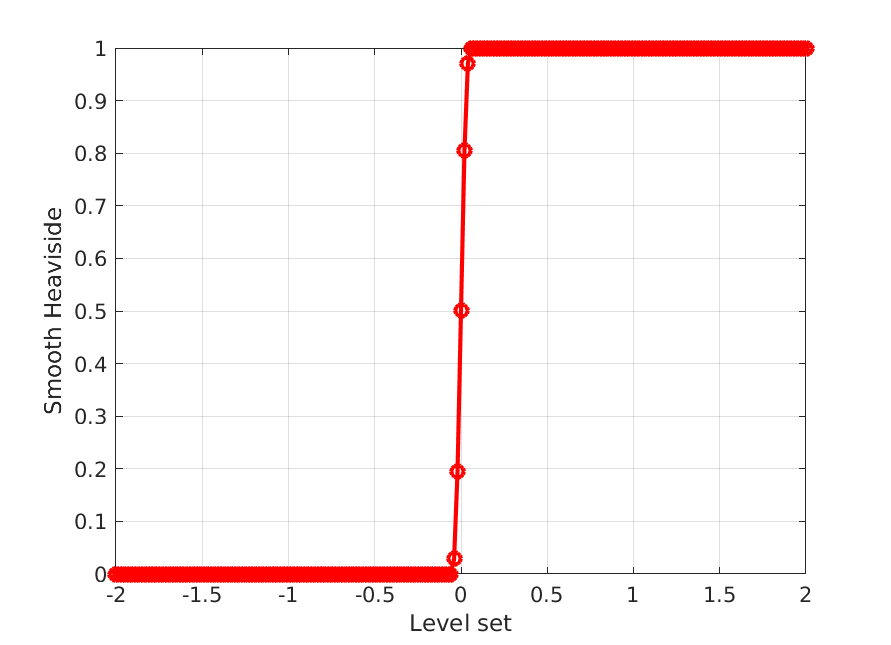
Fig. 4.25 Schematic of 1D smooth Heaviside as a function of
To set up a diffuse interface modeling approach within Aria, at least 3 material
blocks must be declared; one for each phase A and B (for a single level
set), and one multiphase material that combines the two A and B materials:
BEGIN ARIA MATERIAL POS_MAT
  .
  DENSITY = CONSTANT rho = 1
  VISCOSITY = CONSTANT MU = 1.0e-5
  .
END ARIA MATERIAL POS_MAT
.
BEGIN ARIA MATERIAL NEG_MAT
  .
  DENSITY = CONSTANT rho = 1000.0
  VISCOSITY = CONSTANT MU = 1.0e-3
  .
END ARIA MATERIAL NEG_MAT
.
BEGIN ARIA MATERIAL MULTIPHASE
  .
  LEVEL SET HEAVISIDE = INTERPOLATED
  LEVEL SET WIDTH = CONSTANT width = 0.05
  DENSITY = PHASE_AVERAGE
  VISCOSITY = PHASE_AVERAGE
  SURFACE TENSION = CONSTANT sigma = 0.3
  MOMENTUM STRESS = INCOMPRESSIBLE_NEWTONIAN
  .
END ARIA MATERIAL MULTIPHASE
In the above input block, materials POS_MAT and NEG_MAT are declared for
regions where are positive and negative, respectively. A
third block, MULTIPHASE, is declared that defines the smooth Heaviside
variable with the LEVEL SET HEAVISIDE = INTERPOLATED
command and the interface thickness with the LEVEL SET WIDTH
command. Available options for these parameters can be found in Material Properties.
It should be noted that in the above material definitions, a momentum stress
model needs to be only defined for MULTIPHASE, and not POS_MAT or
NEG_MAT. Lastly, material blocks are assigned within the FINITE ELEMENT MODEL scope.
For a mesh that contains a block_1 that will be separated into phases by the
level set field, the following is needed to define a diffuse interface:
BEGIN FINITE ELEMENT MODEL MYFEM
  BEGIN PARAMETERS FOR BLOCK BLOCK_1
    .
    MATERIAL MULTIPHASE
    PHASE A = POS_MAT
    PHASE B = NEG_MAT
    .
  END
END
4.4.7.4. Sharp Interface Approach with CDFEM
Aria offers the option to model the field as a sharp interface
using Sierra/Krino. This is done through the conformal decomposition finite
element method (CDFEM) developed by Noble et al. [36].
This is done by using the initial mesh as a background mesh, and cutting
elements where the level set interfaces crosses into sub-elements to conform to
the interface. The CDFEM approach to interface modeling will separate the
original mesh into two distinct element blocks that represent each phase; the
interface represented by the contour is also represented
as a distinct surface within the mesh, which can be used for any interfacial
boundary applications.
To set up a simulation with CDFEM, a set of material blocks similar to the diffuse interface approach in Diffuse Interface Approach is declared:
BEGIN ARIA MATERIAL POS_MAT
  .
  DENSITY = CONSTANT rho = 1
  VISCOSITY = CONSTANT MU = 1.0e-5
  MOMENTUM STRESS = INCOMPRESSIBLE_NEWTONIAN
  .
END ARIA MATERIAL POS_MAT
.
BEGIN ARIA MATERIAL NEG_MAT
  .
  DENSITY = CONSTANT rho = 1000.0
  VISCOSITY = CONSTANT MU = 1.0e-3
  MOMENTUM STRESS = INCOMPRESSIBLE_NEWTONIAN
  .
END ARIA MATERIAL NEG_MAT
.
BEGIN ARIA MATERIAL POS_NEG_INTERFACE
  .
  SURFACE TENSION = CONSTANT SIGMA = 0.3
  .
END ARIA MATERIAL MULTIPHASE
In the above material blocks, the MOMENTUM STRESS model is defined for each
individual phase; in addition the MULTIPHASE material block that was defined
for the diffuse interface approach is removed. Instead, another material block
POS_NEG_INTERFACE is defined, which will be the material block assigned to
the surface block that represents the interface (which will be automatically
generated by CDFEM).
Within the FINITE ELEMENT MODEL block, the following is defined for our
example of a mesh with a single block block_1 that contains the level set
interface:
BEGIN FINITE ELEMENT MODEL MYFEM
  BEGIN PARAMETERS FOR PHASE POS
    where LS is positive
  END
  .
  BEGIN PARAMETERS FOR PHASE NEG
    where LS is negative
  END
  .
  BEGIN PARAMETERS FOR BLOCK BLOCK_1_POS
    Material POS_MAT
  END
  .
  BEGIN PARAMETERS FOR BLOCK BLOCK_1_NEG
    Material NEG_MAT
  END
  .
  BEGIN PARAMETERS FOR SURFACE SURFACE_BLOCK_1_POS_NEG
    Material POS_NEG_INTERFACE
  END
END
The BEGIN PARAMETERS FOR PHASE command defines the individual block phases
which are separated by the level set interface LS (defined in
Level Set Equation and Interface Definition). From
this, Sierra/Krino will create decomposed blocks based on these phase names:
BLOCK_1_POS and BLOCK_1_NEG. These decomposed blocks must have
materials assigned to them. Lastly, a surface that represents the
contour is created, which is named by combining the block
name and their phases; in our example, this is SURFACE_BLOCK_1_POS_NEG. This
surface requires a material block defining interfacial properties to be defined
on it as well (POS_NEG_INTERFACE in our example). An example of this is
shown in Fig. 4.26, where the original BLOCK_1 mesh
is shown on the left (and is kept as a background mesh by CDFEM); the decomposed
parts BLOCK_1_NEG and BLOCK_1_POS are shown on the right, which are
separated by a the surface SURFACE_BLOCK_1_POS_NEG.
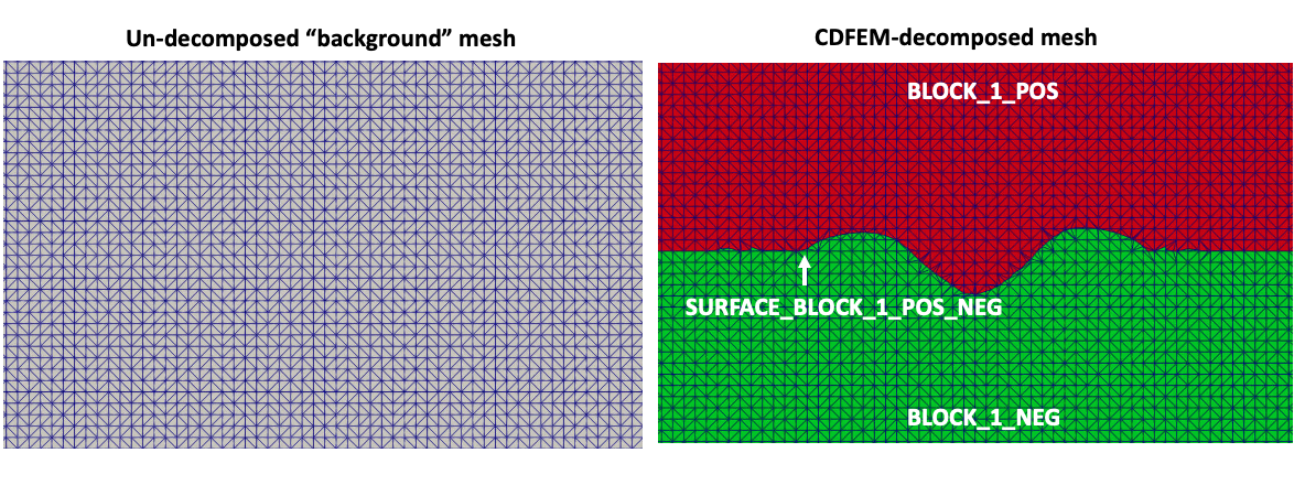
Fig. 4.26 Schematic of an original BLOCK_1 mesh decomposed into separate parts by CDFEM
In addition to defining a level set equation system on the original block
(BLOCK_1), a similar set of equations must be assigned on the
CDFEM-decomposed blocks as well:
EQ LEVEL_SET FOR LEVEL_SET ON BLOCK_1_NEG USING Q1 WITH MASS ADV SUPG
EQ LEVEL_SET FOR LEVEL_SET ON BLOCK_1_POS USING Q1 WITH MASS ADV SUPG
Surfaces that existed on the original mesh will also be decomposed in a similar
manner. For our example, if there existed an original SURFACE_1, that
surface will be decomposed into SURFACE_1_POS and SURFACE_1_NEG, which
will correspond to the positive and negative phases, respectively.
A CDFEM OPTIONS block can be declared at the Aria region scope.
An example of declaring a block like this is shown below:
BEGIN CDFEM OPTIONS
  .
  CDFEM EDGE TOLERANCE = 1.0e-2
  .
END
For a detailed list of CDFEM options and their purposes, refer to CDFEM Options.
4.4.7.5. Diffuse Level Set Approach to Modeling the Capillary Force
Aria offers various formulation for modeling the capillary (surface tension) force. The choice of the various capillary force implementations depend on the level set method used (diffuse or CDFEM); a result of this is that the momentum equation setup is also tailored to the selected level set approach. The following goes over setting up some of the basic implementations of the capillary forces; users should refer to the Command References for all available options.
To set up the momentum equation system, the following can be done (using the example from Diffuse Interface Approach):
EQ CONTINUITY_A FOR PRESSURE ON BLOCK_1 USING Q1 WITH DIV
EQ CONTINUITY_B FOR PRESSURE ON BLOCK_1 USING Q1 WITH DIV
EQ MOMENTUM_A FOR VELOCITY ON BLOCK_1 USING Q1 WITH DIFF ADV SRC SUPG
EQ MOMENTUM_B FOR VELOCITY ON BLOCK_1 USING Q1 WITH DIFF ADV SRC SUPG
The CONTINUITY and MOMENTUM equations are set up for both phases A
and B. As mentioned in Diffuse Interface Approach, any
discontinuities or jumps in the pressure or velocity field across phases A
or B are smeared over the finite interface thickness.
In diffuse interface approaches, the surface tension force is represented as a
continuous volumetric force,  ; this is added as
a source term to the momentum Eq. (3.23).
; this is added as
a source term to the momentum Eq. (3.23).
SOURCE FOR momentum ls A ON block_1 = LS_CAPILLARY
SOURCE FOR momentum ls B ON block_1 = LS_CAPILLARY
The LS_CAPILLARY source model is computed as (after taking a G/FEM residual form):
(4.12)
With taking the form:
(4.13)
where  is a surface tension coefficient (which can
be defined as a generic aria material property, refer to Material Properties
for more details) and
is a surface tension coefficient (which can
be defined as a generic aria material property, refer to Material Properties
for more details) and  is:
is:
(4.14)![\dHeaviSmooth \equiv
\begin{cases}
0 & \;\; \text{if} \;\; |\levelSet| > \heaviWidth\\
\frac{1}{2\heaviWidth}\left[1 + \text{cos}\left(\frac{\pi\levelSet}{\heaviWidth}\right)\right]
& \;\; \text{if} \;\; |\levelSet| \leq \heaviWidth
\end{cases}](data:image/svg+xml;base64,PD94bWwgdmVyc2lvbj0nMS4wJyBlbmNvZGluZz0nVVRGLTgnPz4KPCEtLSBUaGlzIGZpbGUgd2FzIGdlbmVyYXRlZCBieSBkdmlzdmdtIDMuMC4zIC0tPgo8c3ZnIHZlcnNpb249JzEuMScgeG1sbnM9J2h0dHA6Ly93d3cudzMub3JnLzIwMDAvc3ZnJyB4bWxuczp4bGluaz0naHR0cDovL3d3dy53My5vcmcvMTk5OS94bGluaycgd2lkdGg9JzIzMy4yNTk1OTJwdCcgaGVpZ2h0PSc0MS44NDM1MTRwdCcgdmlld0JveD0nNzcuNjQxNjkgLTQxLjg0MzUwMyAyMzMuMjU5NTkyIDQxLjg0MzUxNCc+CjxkZWZzPgo8cGF0aCBpZD0nZzQtOCcgZD0nTTMuODk1NTc1LTEuMzE4MDUyQzUuNDA4ODkzLTEuNDM1MjEyIDYuNDkyNjI0LTIuMzQzMjAzIDYuNDkyNjI0LTMuMzI5MzAxQzYuNDkyNjI0LTQuMzQ0Njg4IDUuMzc5NjAzLTUuMjMzMTUzIDMuODk1NTc1LTUuMzUwMzEzVi01Ljg5NzA2QzMuODk1NTc1LTYuMjI5MDE0IDMuODk1NTc1LTYuMzY1NzAxIDQuODIzMDkyLTYuMzY1NzAxSDUuMTQ1MjgzVi02LjY2ODM2NEM0Ljc5MzgwMi02LjYzOTA3NCAzLjg5NTU3NS02LjYzOTA3NCAzLjQ5NTI3Ny02LjYzOTA3NFMyLjE4Njk4OS02LjYzOTA3NCAxLjgzNTUwOS02LjY2ODM2NFYtNi4zNjU3MDFIMi4xNTc2OTlDMy4wODUyMTctNi4zNjU3MDEgMy4wODUyMTctNi4yMzg3NzcgMy4wODUyMTctNS44OTcwNlYtNS4zNTAzMTNDMS41OTE0MjUtNS4yMDM4NjMgLjU0Njc0Ny00LjMwNTYzNSAuNTQ2NzQ3LTMuMzM5MDY0Qy41NDY3NDctMi4zMzM0MzkgMS42MzA0NzktMS40NjQ1MDIgMy4wODUyMTctMS4zMTgwNTJWLS43NzEzMDRDMy4wODUyMTctLjQzOTM1MSAzLjA4NTIxNy0uMzAyNjY0IDIuMTU3Njk5LS4zMDI2NjRIMS44MzU1MDlWMEMyLjE4Njk4OS0uMDI5MjkgMy4wODUyMTctLjAyOTI5IDMuNDg1NTE0LS4wMjkyOVM0Ljc5MzgwMi0uMDI5MjkgNS4xNDUyODMgMFYtLjMwMjY2NEg0LjgyMzA5MkMzLjg5NTU3NS0uMzAyNjY0IDMuODk1NTc1LS40Mjk1ODcgMy44OTU1NzUtLjc3MTMwNFYtMS4zMTgwNTJaTTMuMDg1MjE3LTEuNTQyNjA4QzEuNjk4ODIyLTEuNzI4MTEyIDEuNTIzMDgyLTIuNzIzOTczIDEuNTIzMDgyLTMuMzI5MzAxQzEuNTIzMDgyLTMuODM2OTk0IDEuNjIwNzE1LTQuOTMwNDg5IDMuMDg1MjE3LTUuMTI1NzU2Vi0xLjU0MjYwOFpNMy44OTU1NzUtNS4xMzU1MTlDNS4yNDI5MTYtNC45NzkzMDYgNS41MTYyOS00LjA4MTA3OCA1LjUxNjI5LTMuMzM5MDY0QzUuNTE2MjktMi43NTMyNjMgNS4zNjk4NC0xLjcwODU4NSAzLjg5NTU3NS0xLjUzMjg0NVYtNS4xMzU1MTlaJy8+CjxwYXRoIGlkPSdnNC00OScgZD0nTTIuODcwNDIzLTYuMjQ4NTQxQzIuODcwNDIzLTYuNDgyODYxIDIuODcwNDIzLTYuNTAyMzg4IDIuNjQ1ODY2LTYuNTAyMzg4QzIuMDQwNTM5LTUuODc3NTM0IDEuMTgxMzY1LTUuODc3NTM0IC44Njg5MzgtNS44Nzc1MzRWLTUuNTc0ODdDMS4wNjQyMDUtNS41NzQ4NyAxLjY0MDI0Mi01LjU3NDg3IDIuMTQ3OTM2LTUuODI4NzE3Vi0uNzcxMzA0QzIuMTQ3OTM2LS40MTk4MjQgMi4xMTg2NDYtLjMwMjY2NCAxLjIzOTk0NS0uMzAyNjY0SC45Mjc1MThWMEMxLjI2OTIzNS0uMDI5MjkgMi4xMTg2NDYtLjAyOTI5IDIuNTA5MTgtLjAyOTI5UzMuNzQ5MTI0LS4wMjkyOSA0LjA5MDg0MSAwVi0uMzAyNjY0SDMuNzc4NDE0QzIuODk5NzEzLS4zMDI2NjQgMi44NzA0MjMtLjQxMDA2IDIuODcwNDIzLS43NzEzMDRWLTYuMjQ4NTQxWicvPgo8cGF0aCBpZD0nZzQtNTAnIGQ9J00xLjIzOTk0NS0uNzUxNzc4TDIuMjc0ODU5LTEuNzU3NDAyQzMuNzk3OTQxLTMuMTA0NzQ0IDQuMzgzNzQyLTMuNjMxOTY0IDQuMzgzNzQyLTQuNjA4Mjk5QzQuMzgzNzQyLTUuNzIxMzIgMy41MDUwNDEtNi41MDIzODggMi4zMTM5MTMtNi41MDIzODhDMS4yMTA2NTUtNi41MDIzODggLjQ4ODE2Ny01LjYwNDE2IC40ODgxNjctNC43MzUyMjJDLjQ4ODE2Ny00LjE4ODQ3NSAuOTc2MzM0LTQuMTg4NDc1IDEuMDA1NjI1LTQuMTg4NDc1QzEuMTcxNjAxLTQuMTg4NDc1IDEuNTEzMzE4LTQuMzA1NjM1IDEuNTEzMzE4LTQuNzA1OTMyQzEuNTEzMzE4LTQuOTU5Nzc5IDEuMzM3NTc4LTUuMjEzNjI2IC45OTU4NjEtNS4yMTM2MjZDLjkxNzc1NC01LjIxMzYyNiAuODk4MjI4LTUuMjEzNjI2IC44Njg5MzgtNS4yMDM4NjNDMS4wOTM0OTUtNS44Mzg0OCAxLjYyMDcxNS02LjE5OTcyNCAyLjE4Njk4OS02LjE5OTcyNEMzLjA3NTQ1NC02LjE5OTcyNCAzLjQ5NTI3Ny01LjQwODg5MyAzLjQ5NTI3Ny00LjYwODI5OUMzLjQ5NTI3Ny0zLjgyNzIzMSAzLjAwNzExLTMuMDU1OTI3IDIuNDcwMTI2LTIuNDUwNkwuNTk1NTY0LS4zNjEyNDRDLjQ4ODE2Ny0uMjUzODQ3IC40ODgxNjctLjIzNDMyIC40ODgxNjcgMEg0LjExMDM2OEw0LjM4Mzc0Mi0xLjY5ODgyMkg0LjEzOTY1OEM0LjA5MDg0MS0xLjQwNTkyMiA0LjAyMjQ5OC0uOTc2MzM0IDMuOTI0ODY1LS44Mjk4ODRDMy44NTY1MjEtLjc1MTc3OCAzLjIxMjE0LS43NTE3NzggMi45OTczNDctLjc1MTc3OEgxLjIzOTk0NVonLz4KPHBhdGggaWQ9J2cyLTI1JyBkPSdNMi41ODcyODYtMy42NDE3MjhIMy42OTA1NDRDMy4zNjgzNTQtMi4xOTY3NTMgMy4yODA0ODQtMS43NzY5MjkgMy4yODA0ODQtMS4xMjI3ODVDMy4yODA0ODQtLjk3NjMzNCAzLjI4MDQ4NC0uNzEyNzI0IDMuMzU4NTkxLS4zODA3N0MzLjQ1NjIyNCAuMDQ4ODE3IDMuNTYzNjIxIC4xMDczOTcgMy43MTAwNzEgLjEwNzM5N0MzLjkwNTMzOCAuMTA3Mzk3IDQuMTEwMzY4LS4wNjgzNDMgNC4xMTAzNjgtLjI2MzYxQzQuMTEwMzY4LS4zMjIxOSA0LjExMDM2OC0uMzQxNzE3IDQuMDUxNzg4LS40Nzg0MDRDMy43Njg2NTEtMS4xODEzNjUgMy43Njg2NTEtMS44MTU5ODIgMy43Njg2NTEtMi4wODkzNTZDMy43Njg2NTEtMi42MDY4MTMgMy44MzY5OTQtMy4xMzQwMzQgMy45NDQzOTEtMy42NDE3MjhINS4wNTc0MTNDNS4xODQzMzYtMy42NDE3MjggNS41MzU4MTYtMy42NDE3MjggNS41MzU4MTYtMy45NzM2ODFDNS41MzU4MTYtNC4yMDgwMDIgNS4zMzA3ODYtNC4yMDgwMDIgNS4xNDUyODMtNC4yMDgwMDJIMS44NzQ1NjJDMS42NTk3NjktNC4yMDgwMDIgMS4yODg3NjItNC4yMDgwMDIgLjg1OTE3NC0zLjc0OTEyNEMuNTE3NDU3LTMuMzY4MzU0IC4yNjM2MS0yLjkxOTI0IC4yNjM2MS0yLjg3MDQyM0MuMjYzNjEtMi44NjA2NiAuMjYzNjEtMi43NzI3OSAuMzgwNzctMi43NzI3OUMuNDU4ODc3LTIuNzcyNzkgLjQ3ODQwNC0yLjgxMTg0MyAuNTM2OTg0LTIuODg5OTVDMS4wMTUzODgtMy42NDE3MjggMS41ODE2NjItMy42NDE3MjggMS43NzY5MjktMy42NDE3MjhIMi4zMzM0MzlDMi4wMjEwMTItMi40NjAzNjMgMS40OTM3OTItMS4yNzg5OTggMS4wODM3MzEtLjM5MDUzNEMxLjAwNTYyNS0uMjQ0MDg0IDEuMDA1NjI1LS4yMjQ1NTcgMS4wMDU2MjUtLjE1NjIxNEMxLjAwNTYyNSAuMDI5MjkgMS4xNjE4MzggLjEwNzM5NyAxLjI4ODc2MiAuMTA3Mzk3QzEuNTgxNjYyIC4xMDczOTcgMS42NTk3NjktLjE2NTk3NyAxLjc3NjkyOS0uNTI3MjIxQzEuOTEzNjE2LS45NzYzMzQgMS45MTM2MTYtLjk5NTg2MSAyLjA0MDUzOS0xLjQ4NDAyOEwyLjU4NzI4Ni0zLjY0MTcyOFonLz4KPHBhdGggaWQ9J2cyLTM0JyBkPSdNMS4zNzY2MzItMi4yMTYyNzlDMS42OTg4MjItMi4wNzk1OTIgMS45ODE5NTktMi4wNzk1OTIgMi4yMTYyNzktMi4wNzk1OTJDMi40NzAxMjYtMi4wNzk1OTIgMy4wMDcxMS0yLjA3OTU5MiAzLjAwNzExLTIuMzgyMjU2QzMuMDA3MTEtMi42MTY1NzYgMi42NjUzOTMtMi42NDU4NjYgMi4yOTQzODYtMi42NDU4NjZDMi4wODkzNTYtMi42NDU4NjYgMS43NDc2MzktMi42MjYzNCAxLjM4NjM5NS0yLjQ2MDM2M0MxLjE2MTgzOC0yLjU3NzUyMyAuOTk1ODYxLTIuNzYzMDI3IC45OTU4NjEtMy4wMjY2MzdDLjk5NTg2MS0zLjYyMjIwMSAxLjk1MjY2OS0zLjk3MzY4MSAyLjgzMTM3LTMuOTczNjgxQzIuOTg3NTgzLTMuOTczNjgxIDMuMzM5MDY0LTMuOTczNjgxIDMuNzI5NTk4LTMuNzAwMzA4QzMuODM2OTk0LTMuNjIyMjAxIDMuODU2NTIxLTMuNjAyNjc0IDMuOTI0ODY1LTMuNjAyNjc0QzQuMDUxNzg4LTMuNjAyNjc0IDQuMTg4NDc1LTMuNzI5NTk4IDQuMTg4NDc1LTMuODY2Mjg1QzQuMTg4NDc1LTQuMDUxNzg4IDMuNTkyOTExLTQuNDIyNzk1IDIuOTI5MDAzLTQuNDIyNzk1QzEuODA2MjE5LTQuNDIyNzk1IC43NTE3NzgtMy43Njg2NTEgLjc1MTc3OC0zLjAyNjYzN0MuNzUxNzc4LTIuNjA2ODEzIDEuMTAzMjU4LTIuMzYyNzI5IDEuMTQyMzExLTIuMzMzNDM5Qy41NjYyNzQtMi4wMTEyNDkgLjI1Mzg0Ny0xLjQ2NDUwMiAuMjUzODQ3LTEuMDE1Mzg4Qy4yNTM4NDctLjM4MDc3IC44MTAzNTggLjIxNDc5NCAxLjg0NTI3MiAuMjE0Nzk0QzMuMTM0MDM0IC4yMTQ3OTQgMy42ODA3ODEtLjY0NDM4MSAzLjY4MDc4MS0uNzkwODMxQzMuNjgwNzgxLS44NDk0MTEgMy42MzE5NjQtLjg4ODQ2NCAzLjU3MzM4NC0uODg4NDY0QzMuNTI0NTY3LS44ODg0NjQgMy40OTUyNzctLjg0OTQxMSAzLjQ3NTc1MS0uODIwMTIxQzMuMzM5MDY0LS41OTU1NjQgMy4xMDQ3NDQtLjIzNDMyIDEuOTMzMTQyLS4yMzQzMkMxLjMzNzU3OC0uMjM0MzIgLjUwNzY5NC0uMzgwNzcgLjUwNzY5NC0xLjA3Mzk2OEMuNTA3Njk0LTEuNDA1OTIyIC43ODEwNjgtMS45MjMzNzkgMS4zNzY2MzItMi4yMTYyNzlaTTEuNjk4ODIyLTIuMzQzMjAzQzEuOTIzMzc5LTIuNDIxMzA5IDIuMTI4NDA5LTIuNDMxMDczIDIuMjk0Mzg2LTIuNDMxMDczQzIuNTM4NDctMi40MzEwNzMgMi41Nzc1MjMtMi40MjEzMDkgMi43NTMyNjMtMi4zNzI0OTNDMi42MDY4MTMtMi4zMDQxNDkgMi41ODcyODYtMi4yOTQzODYgMi4yMTYyNzktMi4yOTQzODZDMi4wMDE0ODYtMi4yOTQzODYgMS44ODQzMjYtMi4yOTQzODYgMS42OTg4MjItMi4zNDMyMDNaJy8+CjxwYXRoIGlkPSdnMy0zNCcgZD0nTTEuOTM4NzMtMy4xODAwNzVDMi4zODUwNTYtMi45OTg3NTUgMi44NTkyNzgtMi45OTg3NTUgMy4xMjQyODQtMi45OTg3NTVDMy40ODY5MjQtMi45OTg3NTUgNC4yMTIyMDQtMi45OTg3NTUgNC4yMTIyMDQtMy40MDMyMzhDNC4yMTIyMDQtMy42NTQyOTYgMy45NDcxOTgtMy43NTE5MyAzLjIzNTg2Ni0zLjc1MTkzQzIuODg3MTczLTMuNzUxOTMgMi40Njg3NDItMy43MTAwODcgMS45ODA1NzMtMy41MDA4NzJDMS41NDgxOTQtMy43MTAwODcgMS4zODA4MjItNC4wMzA4ODQgMS4zODA4MjItNC4zMzc3MzNDMS4zODA4MjItNS4yMDI0OTEgMi43NDc2OTYtNS43MDQ2MDggMy45ODkwNDEtNS43MDQ2MDhDNC4yMjYxNTItNS43MDQ2MDggNC43MjgyNjktNS43MDQ2MDggNS4zMTQwNzItNS4yNzIyMjlDNS4zOTc3NTgtNS4yMTY0MzggNS40Mzk2MDEtNS4xNzQ1OTUgNS41MzcyMzUtNS4xNzQ1OTVDNS43MDQ2MDgtNS4xNzQ1OTUgNS44ODU5MjgtNS4zNTU5MTUgNS44ODU5MjgtNS41MjMyODhDNS44ODU5MjgtNS43NzQzNDYgNS4wNzY5NjEtNi4zMDQzNTkgNC4xMTQ1Ny02LjMwNDM1OUMyLjU1MjQyOC02LjMwNDM1OSAxLjA3Mzk3My01LjM2OTg2MyAxLjA3Mzk3My00LjMzNzczM0MxLjA3Mzk3My0zLjgyMTY2OSAxLjQwODcxNy0zLjUwMDg3MiAxLjY0NTgyOC0zLjMzMzQ5OUMuODM2ODYyLTIuODczMjI1IC4zNjI2NC0yLjEyMDA1IC4zNjI2NC0xLjQzNjYxM0MuMzYyNjQtLjQ3NDIyMiAxLjIyNzM5NyAuMjkyOTAyIDIuNTY2Mzc2IC4yOTI5MDJDNC40MDc0NzIgLjI5MjkwMiA1LjE0NjctLjkzNDQ5NiA1LjE0NjctMS4xMjk3NjNDNS4xNDY3LTEuMTk5NTAyIDUuMDkwOTA5LTEuMjU1MjkzIDUuMDIxMTcxLTEuMjU1MjkzUzQuOTIzNTM3LTEuMjEzNDUgNC44Njc3NDYtMS4xMjk3NjNDNC43MTQzMjEtLjg2NDc1NyA0LjM1MTY4MS0uMzA2ODQ5IDIuNjkxOTA1LS4zMDY4NDlDMS44MjcxNDgtLjMwNjg0OSAuNjgzNDM3LS41MzAwMTIgLjY4MzQzNy0xLjUyMDI5OUMuNjgzNDM3LTEuOTk0NTIxIDEuMDMyMTMtMi43MDU4NTMgMS45Mzg3My0zLjE4MDA3NVpNMi4zNzExMDgtMy4zNDc0NDdDMi43NDc2OTYtMy40NzI5NzYgMy4xMTAzMzYtMy40NzI5NzYgMy4yMDc5Ny0zLjQ3Mjk3NkMzLjU5ODUwNi0zLjQ3Mjk3NiAzLjY2ODI0NC0zLjQ0NTA4MSAzLjg5MTQwNy0zLjM4OTI5QzMuNjU0Mjk2LTMuMjc3NzA5IDMuNjI2NDAxLTMuMjc3NzA5IDMuMTI0Mjg0LTMuMjc3NzA5QzIuODczMjI1LTMuMjc3NzA5IDIuNjUwMDYyLTMuMjc3NzA5IDIuMzcxMTA4LTMuMzQ3NDQ3WicvPgo8cGF0aCBpZD0nZzMtNjInIGQ9J005LjE5MTUzMi0zLjE4MDA3NUM5LjQ1NjUzOC0zLjMwNTYwNCA5LjQ3MDQ4Ni0zLjM4OTI5IDkuNDcwNDg2LTMuNDg2OTI0QzkuNDcwNDg2LTMuNTcwNjEgOS40NDI1OS0zLjY2ODI0NCA5LjE5MTUzMi0zLjc3OTgyNkwxLjY0NTgyOC03LjI1MjgwMkMxLjQ2NDUwOC03LjMzNjQ4OCAxLjQzNjYxMy03LjM1MDQzNiAxLjQwODcxNy03LjM1MDQzNkMxLjI0MTM0NS03LjM1MDQzNiAxLjE0MzcxMS03LjIxMDk1OSAxLjE0MzcxMS03LjA5OTM3N0MxLjE0MzcxMS02LjkzMjAwNSAxLjI1NTI5My02Ljg3NjIxNCAxLjQzNjYxMy02Ljc5MjUyOEw4LjYwNTcyOS0zLjQ4NjkyNEwxLjQyMjY2NS0uMTY3MzcyQzEuMTQzNzExLS4wNDE4NDMgMS4xNDM3MTEgLjA1NTc5MSAxLjE0MzcxMSAuMTM5NDc3QzEuMTQzNzExIC4yNTEwNTkgMS4yNDEzNDUgLjM5MDUzNSAxLjQwODcxNyAuMzkwNTM1QzEuNDM2NjEzIC4zOTA1MzUgMS40NTA1NiAuMzc2NTg4IDEuNjQ1ODI4IC4yOTI5MDJMOS4xOTE1MzItMy4xODAwNzVaJy8+CjxwYXRoIGlkPSdnMy02NCcgZD0nTTYuMzMyMjU0LTQuNjU4NTMxQzYuMjQ4NTY4LTUuNDM5NjAxIDUuNzYwMzk5LTYuMzc0MDk3IDQuNTA1MTA2LTYuMzc0MDk3QzIuNTM4NDgxLTYuMzc0MDk3IC41MzAwMTItNC4zNzk1NzcgLjUzMDAxMi0yLjE2MTg5M0MuNTMwMDEyLTEuMzExMDgzIDEuMTE1ODE2IC4yOTI5MDIgMy4wMTI3MDIgLjI5MjkwMkM2LjMwNDM1OSAuMjkyOTAyIDcuNzEzMDc2LTQuNTA1MTA2IDcuNzEzMDc2LTYuNDE1OTRDNy43MTMwNzYtOC40MjQ0MDggNi41ODMzMTMtOS45NzI2MDMgNC43OTgwMDctOS45NzI2MDNDMi43NzU1OTItOS45NzI2MDMgMi4xNzU4NDEtOC4yMDEyNDUgMi4xNzU4NDEtNy44MjQ2NThDMi4xNzU4NDEtNy42OTkxMjggMi4yNTk1MjctNy4zOTIyNzkgMi42NTAwNjItNy4zOTIyNzlDMy4xMzgyMzItNy4zOTIyNzkgMy4zNDc0NDctNy44Mzg2MDUgMy4zNDc0NDctOC4wNzU3MTZDMy4zNDc0NDctOC41MDgwOTUgMi45MTUwNjgtOC41MDgwOTUgMi43MzM3NDgtOC41MDgwOTVDMy4zMDU2MDQtOS41NDAyMjQgNC4zNjU2MjktOS42Mzc4NTggNC43NDIyMTctOS42Mzc4NThDNS45Njk2MTQtOS42Mzc4NTggNi43NTA2ODUtOC42NjE1MTkgNi43NTA2ODUtNy4wOTkzNzdDNi43NTA2ODUtNi4yMDY3MjUgNi40ODU2NzktNS4xNzQ1OTUgNi4zNDYyMDItNC42NTg1MzFINi4zMzIyNTRaTTMuMDU0NTQ1LS4wODM2ODZDMS43NDM0NjItLjA4MzY4NiAxLjUyMDI5OS0xLjExNTgxNiAxLjUyMDI5OS0xLjcwMTYxOUMxLjUyMDI5OS0yLjMxNTMxOCAxLjkxMDgzNC0zLjc1MTkzIDIuMTIwMDUtNC4yNjc5OTVDMi4zMDEzNy00LjY4NjQyNiAzLjA5NjM4OS02LjA5NTE0MyA0LjU0Njk0OS02LjA5NTE0M0M1LjgxNjE4OS02LjA5NTE0MyA2LjEwOTA5MS00Ljk5MzI3NSA2LjEwOTA5MS00LjI0MDFDNi4xMDkwOTEtMy4yMDc5NyA1LjIwMjQ5MS0uMDgzNjg2IDMuMDU0NTQ1LS4wODM2ODZaJy8+CjxwYXRoIGlkPSdnMy03MicgZD0nTTEwLjQzMjg3Ny04LjUwODA5NUMxMC41NTg0MDYtOC45ODIzMTYgMTAuNTg2MzAxLTkuMTIxNzkzIDExLjU3NjU4OC05LjEyMTc5M0MxMS44Mjc2NDYtOS4xMjE3OTMgMTEuOTY3MTIzLTkuMTIxNzkzIDExLjk2NzEyMy05LjM3Mjg1MkMxMS45NjcxMjMtOS41MjYyNzYgMTEuODQxNTk0LTkuNTI2Mjc2IDExLjc1NzkwOC05LjUyNjI3NkMxMS41MDY4NDktOS41MjYyNzYgMTEuMjEzOTQ4LTkuNDk4MzgxIDEwLjk0ODk0MS05LjQ5ODM4MUg5LjMwMzExM0M5LjAzODEwNy05LjQ5ODM4MSA4Ljc0NTIwNS05LjUyNjI3NiA4LjQ4MDE5OS05LjUyNjI3NkM4LjM4MjU2NS05LjUyNjI3NiA4LjIxNTE5My05LjUyNjI3NiA4LjIxNTE5My05LjI2MTI3QzguMjE1MTkzLTkuMTIxNzkzIDguMzEyODI3LTkuMTIxNzkzIDguNTc3ODMzLTkuMTIxNzkzQzkuNDE0Njk1LTkuMTIxNzkzIDkuNDE0Njk1LTkuMDEwMjEyIDkuNDE0Njk1LTguODU2Nzg3QzkuNDE0Njk1LTguODI4ODkyIDkuNDE0Njk1LTguNzQ1MjA1IDkuMzU4OTA0LTguNTM1OTlMOC41MDgwOTUtNS4xNjA2NDhINC4yOTU4OUw1LjEzMjc1Mi04LjUwODA5NUM1LjI1ODI4MS04Ljk4MjMxNiA1LjI4NjE3Ny05LjEyMTc5MyA2LjI3NjQ2My05LjEyMTc5M0M2LjUyNzUyMi05LjEyMTc5MyA2LjY2Njk5OS05LjEyMTc5MyA2LjY2Njk5OS05LjM3Mjg1MkM2LjY2Njk5OS05LjUyNjI3NiA2LjU0MTQ2OS05LjUyNjI3NiA2LjQ1Nzc4My05LjUyNjI3NkM2LjIwNjcyNS05LjUyNjI3NiA1LjkxMzgyMy05LjQ5ODM4MSA1LjY0ODgxNy05LjQ5ODM4MUg0LjAwMjk4OUMzLjczNzk4My05LjQ5ODM4MSAzLjQ0NTA4MS05LjUyNjI3NiAzLjE4MDA3NS05LjUyNjI3NkMzLjA4MjQ0MS05LjUyNjI3NiAyLjkxNTA2OC05LjUyNjI3NiAyLjkxNTA2OC05LjI2MTI3QzIuOTE1MDY4LTkuMTIxNzkzIDMuMDEyNzAyLTkuMTIxNzkzIDMuMjc3NzA5LTkuMTIxNzkzQzQuMTE0NTctOS4xMjE3OTMgNC4xMTQ1Ny05LjAxMDIxMiA0LjExNDU3LTguODU2Nzg3QzQuMTE0NTctOC44Mjg4OTIgNC4xMTQ1Ny04Ljc0NTIwNSA0LjA1ODc4LTguNTM1OTlMMi4xNzU4NDEtMS4wMzIxM0MyLjA1MDMxMS0uNTQzOTYgMi4wMjI0MTYtLjQwNDQ4MyAxLjA2MDAyNS0uNDA0NDgzQy43MzkyMjgtLjQwNDQ4MyAuNjQxNTk0LS40MDQ0ODMgLjY0MTU5NC0uMTM5NDc3Qy42NDE1OTQgMCAuNzk1MDE5IDAgLjgzNjg2MiAwQzEuMDg3OTIgMCAxLjM4MDgyMi0uMDI3ODk1IDEuNjQ1ODI4LS4wMjc4OTVIMy4yOTE2NTZDMy41NTY2NjMtLjAyNzg5NSAzLjg0OTU2NCAwIDQuMTE0NTcgMEM0LjIyNjE1MiAwIDQuMzc5NTc3IDAgNC4zNzk1NzctLjI2NTAwNkM0LjM3OTU3Ny0uNDA0NDgzIDQuMjU0MDQ3LS40MDQ0ODMgNC4wNDQ4MzItLjQwNDQ4M0MzLjE5NDAyMi0uNDA0NDgzIDMuMTk0MDIyLS41MTYwNjUgMy4xOTQwMjItLjY1NTU0MkMzLjE5NDAyMi0uNjY5NDg5IDMuMTk0MDIyLS43NjcxMjMgMy4yMjE5MTgtLjg3ODcwNUw0LjE4NDMwOS00Ljc1NjE2NEg4LjQxMDQ2MUM4LjE3MzM1LTMuODM1NjE2IDcuNDYyMDE3LS45MjA1NDggNy40MzQxMjItLjgzNjg2MkM3LjI4MDY5Ny0uNDE4NDMxIDcuMDU3NTM0LS40MTg0MzEgNi4yMzQ2Mi0uNDA0NDgzQzYuMDY3MjQ4LS40MDQ0ODMgNS45NDE3MTktLjQwNDQ4MyA1Ljk0MTcxOS0uMTM5NDc3QzUuOTQxNzE5IDAgNi4wOTUxNDMgMCA2LjEzNjk4NiAwQzYuMzg4MDQ1IDAgNi42ODA5NDYtLjAyNzg5NSA2Ljk0NTk1My0uMDI3ODk1SDguNTkxNzgxQzguODU2Nzg3LS4wMjc4OTUgOS4xNDk2ODkgMCA5LjQxNDY5NSAwQzkuNTI2Mjc2IDAgOS42Nzk3MDEgMCA5LjY3OTcwMS0uMjY1MDA2QzkuNjc5NzAxLS40MDQ0ODMgOS41NTQxNzItLjQwNDQ4MyA5LjM0NDk1Ni0uNDA0NDgzQzguNDk0MTQ3LS40MDQ0ODMgOC40OTQxNDctLjUxNjA2NSA4LjQ5NDE0Ny0uNjU1NTQyQzguNDk0MTQ3LS42Njk0ODkgOC40OTQxNDctLjc2NzEyMyA4LjUyMjA0Mi0uODc4NzA1TDEwLjQzMjg3Ny04LjUwODA5NVonLz4KPHBhdGggaWQ9J2cwLTAnIGQ9J001Ljc2MDM5OSAxNi4wMjU5MDNDNS43NjAzOTkgMTUuOTcwMTEyIDUuNzMyNTAzIDE1Ljk0MjIxNyA1LjcwNDYwOCAxNS45MDAzNzRDNS4wNjMwMTQgMTUuMjE2OTM2IDQuMTE0NTcgMTQuMDg3MTczIDMuNTI4NzY3IDExLjgxMzY5OUMzLjIwNzk3IDEwLjU0NDQ1OCAzLjA4MjQ0MSA5LjEwNzg0NiAzLjA4MjQ0MSA3LjgxMDcxQzMuMDgyNDQxIDQuMTQyNDY2IDMuOTYxMTQ2IDEuNTc2MDkgNS42MzQ4NjktLjIzNzExMUM1Ljc2MDM5OS0uMzYyNjQgNS43NjAzOTktLjM5MDUzNSA1Ljc2MDM5OS0uNDE4NDMxQzUuNzYwMzk5LS41NTc5MDggNS42NDg4MTctLjU1NzkwOCA1LjU5MzAyNi0uNTU3OTA4QzUuMzgzODExLS41NTc5MDggNC42MzA2MzUgLjI3ODk1NCA0LjQ0OTMxNSAuNDg4MTY5QzMuMDI2NjUgMi4xNzU4NDEgMi4xMjAwNSA0LjY4NjQyNiAyLjEyMDA1IDcuNzk2NzYyQzIuMTIwMDUgOS43NzczMzUgMi40Njg3NDIgMTIuNTgwODIyIDQuMjk1ODkgMTQuOTM3OTgzQzQuNDM1MzY3IDE1LjEwNTM1NSA1LjM0MTk2OCAxNi4xNjUzOCA1LjU5MzAyNiAxNi4xNjUzOEM1LjY0ODgxNyAxNi4xNjUzOCA1Ljc2MDM5OSAxNi4xNjUzOCA1Ljc2MDM5OSAxNi4wMjU5MDNaJy8+CjxwYXRoIGlkPSdnMC0xJyBkPSdNNC4yNTQwNDcgNy44MTA3MUM0LjI1NDA0NyA1LjgzMDEzNyAzLjkwNTM1NSAzLjAyNjY1IDIuMDc4MjA3IC42Njk0ODlDMS45Mzg3MyAuNTAyMTE3IDEuMDMyMTMtLjU1NzkwOCAuNzgxMDcxLS41NTc5MDhDLjcxMTMzMy0uNTU3OTA4IC42MTM2OTktLjUzMDAxMiAuNjEzNjk5LS40MTg0MzFDLjYxMzY5OS0uMzYyNjQgLjY0MTU5NC0uMzIwNzk3IC42OTczODUtLjI3ODk1NEMxLjM2Njg3NCAuNDQ2MzI2IDIuMjczNDc0IDEuNTc2MDkgMi44NDUzMyAzLjc5Mzc3M0MzLjE2NjEyNyA1LjA2MzAxNCAzLjI5MTY1NiA2LjQ5OTYyNiAzLjI5MTY1NiA3Ljc5Njc2MkMzLjI5MTY1NiA5LjIwNTQ3OSAzLjE2NjEyNyAxMC42MjgxNDQgMi44MDM0ODcgMTEuOTk1MDE5QzIuMjczNDc0IDEzLjk0NzY5NiAxLjQ1MDU2IDE1LjA2MzUxMiAuNzM5MjI4IDE1Ljg0NDU4M0MuNjEzNjk5IDE1Ljk3MDExMiAuNjEzNjk5IDE1Ljk5ODAwNyAuNjEzNjk5IDE2LjAyNTkwM0MuNjEzNjk5IDE2LjEzNzQ4NCAuNzExMzMzIDE2LjE2NTM4IC43ODEwNzEgMTYuMTY1MzhDLjk5MDI4NiAxNi4xNjUzOCAxLjc1NzQxIDE1LjMxNDU3IDEuOTI0NzgyIDE1LjExOTMwM0MzLjM0NzQ0NyAxMy40MzE2MzEgNC4yNTQwNDcgMTAuOTIxMDQ2IDQuMjU0MDQ3IDcuODEwNzFaJy8+CjxwYXRoIGlkPSdnMC0yJyBkPSdNMi44MTc0MzUgMTYuMTY1MzhINS40OTUzOTJWMTUuNjA3NDcySDMuMzc1MzQyVjBINS40OTUzOTJWLS41NTc5MDhIMi44MTc0MzVWMTYuMTY1MzhaJy8+CjxwYXRoIGlkPSdnMC0zJyBkPSdNMi45ODQ4MDcgMTYuMTY1MzhWLS41NTc5MDhILjMwNjg0OVYwSDIuNDI2ODk5VjE1LjYwNzQ3MkguMzA2ODQ5VjE2LjE2NTM4SDIuOTg0ODA3WicvPgo8cGF0aCBpZD0nZzAtNDAnIGQ9J002LjI5MDQxMSAyNS40ODI0NDFDNi4yOTA0MTEgMjMuOTQ4MTk0IDUuMjMwMzg2IDIxLjU5MTAzNCAyLjgwMzQ4NyAyMC4zNjM2MzZDNC4zMDk4MzggMTkuNTU0NjcgNi4xMDkwOTEgMTcuOTIyNzkgNi4yNzY0NjMgMTUuMzE0NTdMNi4yOTA0MTEgMTUuMjMwODg0VjUuNTY1MTMxQzYuMjkwNDExIDQuNDIxNDIgNi4yOTA0MTEgNC4xNzAzNjEgNi40MDE5OTMgMy42NDAzNDlDNi42NTMwNTEgMi41MjQ1MzMgNy4zMjI1NCAxLjE0MzcxMSA5LjA5Mzg5OCAuMDk3NjM0QzkuMjA1NDc5IC4wMjc4OTUgOS4yMTk0MjcgLjAxMzk0OCA5LjIxOTQyNy0uMjM3MTExQzkuMjE5NDI3LS41NDM5NiA5LjIwNTQ3OS0uNTU3OTA4IDguODk4NjMtLjU1NzkwOEM4LjY0NzU3Mi0uNTU3OTA4IDguNjE5Njc2LS41NTc5MDggOC4yNDMwODgtLjMzNDc0NUM1LjExODgwNCAxLjQzNjYxMyA0LjkzNzQ4NCA0LjAzMDg4NCA0LjkzNzQ4NCA0LjUxOTA1NFYxNC40MzU4NjZDNC45Mzc0ODQgMTUuNDQwMSA0LjkzNzQ4NCAxNi41Njk4NjMgNC4yMTIyMDQgMTcuODUzMDUxQzMuNTcwNjEgMTguOTk2NzYyIDIuODE3NDM1IDE5LjU2ODYxOCAyLjIxNzY4NCAxOS45NzMxMDFDMi4wMjI0MTYgMjAuMDk4NjMgMi4wMDg0NjggMjAuMTEyNTc4IDIuMDA4NDY4IDIwLjM0OTY4OUMyLjAwODQ2OCAyMC42MDA3NDcgMi4wMjI0MTYgMjAuNjE0Njk1IDIuMTMzOTk4IDIwLjY4NDQzM0MzLjMxOTU1MiAyMS40NjU1MDQgNC41ODg3OTIgMjIuNzA2ODQ5IDQuODk1NjQxIDI0Ljk4MDMyNEM0LjkzNzQ4NCAyNS4yODcxNzMgNC45Mzc0ODQgMjUuMzE1MDY4IDQuOTM3NDg0IDI1LjQ4MjQ0MVYzNi4xOTQyNzFDNC45Mzc0ODQgMzcuMzI0MDM1IDUuNjM0ODY5IDM5LjY2NzI0OCA4LjMyNjc3NSA0MS4wODk5MTNDOC42NDc1NzIgNDEuMjcxMjMzIDguNjc1NDY3IDQxLjI3MTIzMyA4Ljg5ODYzIDQxLjI3MTIzM0M5LjIwNTQ3OSA0MS4yNzEyMzMgOS4yMTk0MjcgNDEuMjU3Mjg1IDkuMjE5NDI3IDQwLjk1MDQzNkM5LjIxOTQyNyA0MC42OTkzNzcgOS4yMDU0NzkgNDAuNjg1NDMgOS4xNDk2ODkgNDAuNjU3NTM0QzguNTQ5OTM4IDQwLjI4MDk0NiA2LjcyMjc5IDM5LjE3OTA3OCA2LjM0NjIwMiAzNi43NTIxNzlDNi4yOTA0MTEgMzYuMzg5NTM5IDYuMjkwNDExIDM2LjM2MTY0NCA2LjI5MDQxMSAzNi4xODAzMjRWMjUuNDgyNDQxWicvPgo8cGF0aCBpZD0nZzUtOCcgZD0nTTUuNDI1NjU0LTEuODQxMDk2QzcuNTQ1NzA0LTIuMDIyNDE2IDkuMDkzODk4LTMuMzE5NTUyIDkuMDkzODk4LTQuNzU2MTY0QzkuMDkzODk4LTYuMjQ4NTY4IDcuNTAzODYxLTcuNTAzODYxIDUuNDI1NjU0LTcuNjg1MTgxVi04LjQ1MjMwNEM1LjQyNTY1NC04Ljk1NDQyMSA1LjQ1MzU0OS05LjEyMTc5MyA2LjY2Njk5OS05LjEyMTc5M0g3LjA4NTQzVi05LjUyNjI3NkM2LjcwODg0Mi05LjQ5ODM4MSA1LjM1NTkxNS05LjQ5ODM4MSA0Ljg5NTY0MS05LjQ5ODM4MVMzLjA4MjQ0MS05LjQ5ODM4MSAyLjcwNTg1My05LjUyNjI3NlYtOS4xMjE3OTNIMy4xMjQyODRDNC4zMzc3MzMtOS4xMjE3OTMgNC4zNjU2MjktOC45NTQ0MjEgNC4zNjU2MjktOC40NTIzMDRWLTcuNjcxMjMzQzIuMjAzNzM2LTcuNDc1OTY1IC43NTMxNzYtNi4xNTA5MzQgLjc1MzE3Ni00Ljc3MDExMkMuNzUzMTc2LTMuMzMzNDk5IDIuMjQ1NTc5LTIuMDUwMzExIDQuMzY1NjI5LTEuODU1MDQ0Vi0xLjA3Mzk3M0M0LjM2NTYyOS0uNTcxODU2IDQuMzM3NzMzLS40MDQ0ODMgMy4xMjQyODQtLjQwNDQ4M0gyLjcwNTg1M1YwQzMuMDgyNDQxLS4wMjc4OTUgNC40MzUzNjctLjAyNzg5NSA0Ljg5NTY0MS0uMDI3ODk1UzYuNzA4ODQyLS4wMjc4OTUgNy4wODU0MyAwVi0uNDA0NDgzSDYuNjY2OTk5QzUuNDUzNTQ5LS40MDQ0ODMgNS40MjU2NTQtLjU3MTg1NiA1LjQyNTY1NC0xLjA3Mzk3M1YtMS44NDEwOTZaTTQuMzY1NjI5LTIuMTQ3OTQ1QzIuODQ1MzMtMi4zNDMyMTMgMi4wMjI0MTYtMy4yMzU4NjYgMi4wMjI0MTYtNC43NTYxNjRDMi4wMjI0MTYtNi4yOTA0MTEgMi44MzEzODItNy4xODMwNjQgNC4zNjU2MjktNy4zNzgzMzFWLTIuMTQ3OTQ1Wk01LjQyNTY1NC03LjM5MjI3OUM3LjA1NzUzNC03LjE4MzA2NCA3LjgyNDY1OC02LjI0ODU2OCA3LjgyNDY1OC00Ljc3MDExMkM3LjgyNDY1OC0zLjMxOTU1MiA3LjExMzMyNS0yLjM1NzE2MSA1LjQyNTY1NC0yLjEzMzk5OFYtNy4zOTIyNzlaJy8+CjxwYXRoIGlkPSdnNS00MycgZD0nTTUuNTY1MTMxLTMuMjIxOTE4SDkuNDE0Njk1QzkuNjA5OTYzLTMuMjIxOTE4IDkuODYxMDIxLTMuMjIxOTE4IDkuODYxMDIxLTMuNDcyOTc2QzkuODYxMDIxLTMuNzM3OTgzIDkuNjIzOTEtMy43Mzc5ODMgOS40MTQ2OTUtMy43Mzc5ODNINS41NjUxMzFWLTcuNTg3NTQ3QzUuNTY1MTMxLTcuNzgyODE0IDUuNTY1MTMxLTguMDMzODczIDUuMzE0MDcyLTguMDMzODczQzUuMDQ5MDY2LTguMDMzODczIDUuMDQ5MDY2LTcuNzk2NzYyIDUuMDQ5MDY2LTcuNTg3NTQ3Vi0zLjczNzk4M0gxLjE5OTUwMkMxLjAwNDIzNC0zLjczNzk4MyAuNzUzMTc2LTMuNzM3OTgzIC43NTMxNzYtMy40ODY5MjRDLjc1MzE3Ni0zLjIyMTkxOCAuOTkwMjg2LTMuMjIxOTE4IDEuMTk5NTAyLTMuMjIxOTE4SDUuMDQ5MDY2Vi42Mjc2NDZDNS4wNDkwNjYgLjgyMjkxNCA1LjA0OTA2NiAxLjA3Mzk3MyA1LjMwMDEyNSAxLjA3Mzk3M0M1LjU2NTEzMSAxLjA3Mzk3MyA1LjU2NTEzMSAuODM2ODYyIDUuNTY1MTMxIC42Mjc2NDZWLTMuMjIxOTE4WicvPgo8cGF0aCBpZD0nZzUtNDgnIGQ9J002LjI0ODU2OC00LjQ2MzI2M0M2LjI0ODU2OC01LjYyMDkyMiA2LjE3ODgyOS02Ljc1MDY4NSA1LjY3NjcxMi03LjgxMDcxQzUuMTA0ODU3LTguOTY4MzY5IDQuMTAwNjIzLTkuMjc1MjE4IDMuNDE3MTg2LTkuMjc1MjE4QzIuNjA4MjE5LTkuMjc1MjE4IDEuNjE3OTMzLTguODcwNzM1IDEuMTAxODY4LTcuNzEzMDc2Qy43MTEzMzMtNi44MzQzNzEgLjU3MTg1Ni01Ljk2OTYxNCAuNTcxODU2LTQuNDYzMjYzQy41NzE4NTYtMy4xMTAzMzYgLjY2OTQ4OS0yLjA5MjE1NCAxLjE3MTYwNi0xLjEwMTg2OEMxLjcxNTU2Ny0uMDQxODQzIDIuNjc3OTU4IC4yOTI5MDIgMy40MDMyMzggLjI5MjkwMkM0LjYxNjY4NyAuMjkyOTAyIDUuMzE0MDcyLS40MzIzNzkgNS43MTg1NTUtMS4yNDEzNDVDNi4yMjA2NzItMi4yODc0MjIgNi4yNDg1NjgtMy42NTQyOTYgNi4yNDg1NjgtNC40NjMyNjNaTTMuNDAzMjM4IC4wMTM5NDhDMi45NTY5MTIgLjAxMzk0OCAyLjA1MDMxMS0uMjM3MTExIDEuNzg1MzA1LTEuNzU3NDFDMS42MzE4OC0yLjU5NDI3MSAxLjYzMTg4LTMuNjU0Mjk2IDEuNjMxODgtNC42MzA2MzVDMS42MzE4OC01Ljc3NDM0NiAxLjYzMTg4LTYuODA2NDc2IDEuODU1MDQ0LTcuNjI5MzlDMi4wOTIxNTQtOC41NjM4ODUgMi44MDM0ODctOC45OTYyNjQgMy40MDMyMzgtOC45OTYyNjRDMy45MzMyNS04Ljk5NjI2NCA0Ljc0MjIxNy04LjY3NTQ2NyA1LjAwNzIyMy03LjQ3NTk2NUM1LjE4ODU0My02LjY4MDk0NiA1LjE4ODU0My01LjU3OTA3OCA1LjE4ODU0My00LjYzMDYzNUM1LjE4ODU0My0zLjY5NjEzOSA1LjE4ODU0My0yLjYzNjExNSA1LjAzNTExOC0xLjc4NTMwNUM0Ljc3MDExMi0uMjUxMDU5IDMuODkxNDA3IC4wMTM5NDggMy40MDMyMzggLjAxMzk0OFonLz4KPHBhdGggaWQ9J2c1LTQ5JyBkPSdNNC4wMTY5MzYtOC45NDA0NzNDNC4wMTY5MzYtOS4yNjEyNyA0LjAxNjkzNi05LjI3NTIxOCAzLjczNzk4My05LjI3NTIxOEMzLjQwMzIzOC04Ljg5ODYzIDIuNzA1ODUzLTguMzgyNTY1IDEuMjY5MjQtOC4zODI1NjVWLTcuOTc4MDgyQzEuNTkwMDM3LTcuOTc4MDgyIDIuMjg3NDIyLTcuOTc4MDgyIDMuMDU0NTQ1LTguMzQwNzIyVi0xLjA3Mzk3M0MzLjA1NDU0NS0uNTcxODU2IDMuMDEyNzAyLS40MDQ0ODMgMS43ODUzMDUtLjQwNDQ4M0gxLjM1MjkyN1YwQzEuNzI5NTE0LS4wMjc4OTUgMy4wODI0NDEtLjAyNzg5NSAzLjU0MjcxNS0uMDI3ODk1UzUuMzQxOTY4LS4wMjc4OTUgNS43MTg1NTUgMFYtLjQwNDQ4M0g1LjI4NjE3N0M0LjA1ODc4LS40MDQ0ODMgNC4wMTY5MzYtLjU3MTg1NiA0LjAxNjkzNi0xLjA3Mzk3M1YtOC45NDA0NzNaJy8+CjxwYXRoIGlkPSdnNS05OScgZD0nTTUuMDQ5MDY2LTUuMTYwNjQ4QzQuODgxNjk0LTUuMTYwNjQ4IDQuMzY1NjI5LTUuMTYwNjQ4IDQuMzY1NjI5LTQuNTg4NzkyQzQuMzY1NjI5LTQuMjU0MDQ3IDQuNjAyNzQtNC4wMTY5MzYgNC45Mzc0ODQtNC4wMTY5MzZDNS4yNTgyODEtNC4wMTY5MzYgNS41MjMyODgtNC4yMTIyMDQgNS41MjMyODgtNC42MTY2ODdDNS41MjMyODgtNS41NTExODMgNC41NDY5NDktNi4yMjA2NzIgMy40MTcxODYtNi4yMjA2NzJDMS43ODUzMDUtNi4yMjA2NzIgLjQ4ODE2OS00Ljc3MDExMiAuNDg4MTY5LTMuMDEyNzAyQy40ODgxNjktMS4yMjczOTcgMS44MjcxNDggLjEzOTQ3NyAzLjQwMzIzOCAuMTM5NDc3QzUuMjQ0MzM0IC4xMzk0NzcgNS42NjI3NjUtMS41MzQyNDcgNS42NjI3NjUtMS42NTk3NzZTNS41NjUxMzEtMS43ODUzMDUgNS41MjMyODgtMS43ODUzMDVDNS4zOTc3NTgtMS43ODUzMDUgNS4zODM4MTEtMS43NDM0NjIgNS4zNDE5NjgtMS41NzYwOUM1LjAzNTExOC0uNTg1ODAzIDQuMjgxOTQzLS4xNjczNzIgMy41Mjg3NjctLjE2NzM3MkMyLjY3Nzk1OC0uMTY3MzcyIDEuNTQ4MTk0LS45MDY2IDEuNTQ4MTk0LTMuMDI2NjVDMS41NDgxOTQtNS4zNDE5NjggMi43MzM3NDgtNS45MTM4MjMgMy40MzExMzMtNS45MTM4MjNDMy45NjExNDYtNS45MTM4MjMgNC43MjgyNjktNS43MDQ2MDggNS4wNDkwNjYtNS4xNjA2NDhaJy8+CjxwYXRoIGlkPSdnNS0xMDInIGQ9J00yLjM5OTAwNC01LjYwNjk3NEgzLjk3NTA5M1YtNi4wMTE0NTdIMi4zNzExMDhWLTcuNjQzMzM3QzIuMzcxMTA4LTguODk4NjMgMy4wMTI3MDItOS41NDAyMjQgMy41ODQ1NTgtOS41NDAyMjRDMy42OTYxMzktOS41NDAyMjQgMy45MDUzNTUtOS41MTIzMjkgNC4wNzI3MjctOS40Mjg2NDNDNC4wMTY5MzYtOS40MTQ2OTUgMy42NjgyNDQtOS4yODkxNjYgMy42NjgyNDQtOC44ODQ2ODJDMy42NjgyNDQtOC41NjM4ODUgMy44OTE0MDctOC4zNDA3MjIgNC4yMTIyMDQtOC4zNDA3MjJDNC41NDY5NDktOC4zNDA3MjIgNC43NzAxMTItOC41NjM4ODUgNC43NzAxMTItOC44OTg2M0M0Ljc3MDExMi05LjQxNDY5NSA0LjI2Nzk5NS05LjgxOTE3OCAzLjU5ODUwNi05LjgxOTE3OEMyLjYyMjE2Ny05LjgxOTE3OCAxLjUyMDI5OS05LjA2NjAwMiAxLjUyMDI5OS03LjY0MzMzN1YtNi4wMTE0NTdILjQzMjM3OVYtNS42MDY5NzRIMS41MjAyOTlWLTEuMDMyMTNDMS41MjAyOTktLjQwNDQ4MyAxLjM2Njg3NC0uNDA0NDgzIC40NjAyNzQtLjQwNDQ4M1YwQy44NTA4MDktLjAyNzg5NSAxLjYxNzkzMy0uMDI3ODk1IDIuMDM2MzY0LS4wMjc4OTVDMi40MTI5NTEtLjAyNzg5NSAzLjQwMzIzOC0uMDI3ODk1IDMuNzI0MDM1IDBWLS40MDQ0ODNIMy40NDUwODFDMi40MjY4OTktLjQwNDQ4MyAyLjM5OTAwNC0uNTU3OTA4IDIuMzk5MDA0LTEuMDYwMDI1Vi01LjYwNjk3NFonLz4KPHBhdGggaWQ9J2c1LTEwNScgZD0nTTIuNDI2ODk5LTguNTkxNzgxQzIuNDI2ODk5LTguOTU0NDIxIDIuMTMzOTk4LTkuMjc1MjE4IDEuNzQzNDYyLTkuMjc1MjE4QzEuMzgwODIyLTkuMjc1MjE4IDEuMDczOTczLTguOTgyMzE2IDEuMDczOTczLTguNjA1NzI5QzEuMDczOTczLTguMTg3Mjk4IDEuNDA4NzE3LTcuOTIyMjkxIDEuNzQzNDYyLTcuOTIyMjkxQzIuMTc1ODQxLTcuOTIyMjkxIDIuNDI2ODk5LTguMjg0OTMyIDIuNDI2ODk5LTguNTkxNzgxWk0uNTAyMTE3LTUuOTk3NTA5Vi01LjU5MzAyNkMxLjM5NDc3LTUuNTkzMDI2IDEuNTIwMjk5LTUuNTA5MzQgMS41MjAyOTktNC44MjU5MDNWLTEuMDMyMTNDMS41MjAyOTktLjQwNDQ4MyAxLjM2Njg3NC0uNDA0NDgzIC40NjAyNzQtLjQwNDQ4M1YwQy44NTA4MDktLjAyNzg5NSAxLjUyMDI5OS0uMDI3ODk1IDEuOTI0NzgyLS4wMjc4OTVDMi4wNzgyMDctLjAyNzg5NSAyLjg4NzE3My0uMDI3ODk1IDMuMzYxMzk1IDBWLS40MDQ0ODNDMi40NTQ3OTUtLjQwNDQ4MyAyLjM5OTAwNC0uNDc0MjIyIDIuMzk5MDA0LTEuMDE4MTgyVi02LjE1MDkzNEwuNTAyMTE3LTUuOTk3NTA5WicvPgo8cGF0aCBpZD0nZzUtMTExJyBkPSdNNi40MDE5OTMtMi45ODQ4MDdDNi40MDE5OTMtNC43ODQwNiA1LjAzNTExOC02LjIyMDY3MiAzLjQxNzE4Ni02LjIyMDY3MkMxLjc0MzQ2Mi02LjIyMDY3MiAuNDE4NDMxLTQuNzQyMjE3IC40MTg0MzEtMi45ODQ4MDdDLjQxODQzMS0xLjE5OTUwMiAxLjgxMzIgLjEzOTQ3NyAzLjQwMzIzOCAuMTM5NDc3QzUuMDQ5MDY2IC4xMzk0NzcgNi40MDE5OTMtMS4yMjczOTcgNi40MDE5OTMtMi45ODQ4MDdaTTMuNDE3MTg2LS4xNjczNzJDMi45MDExMjEtLjE2NzM3MiAyLjI3MzQ3NC0uMzkwNTM1IDEuODY4OTkxLTEuMDczOTczQzEuNDkyNDAzLTEuNzAxNjE5IDEuNDc4NDU2LTIuNTI0NTMzIDEuNDc4NDU2LTMuMTEwMzM2QzEuNDc4NDU2LTMuNjQwMzQ5IDEuNDc4NDU2LTQuNDkxMTU4IDEuOTEwODM0LTUuMTE4ODA0QzIuMzAxMzctNS43MTg1NTUgMi45MTUwNjgtNS45NDE3MTkgMy40MDMyMzgtNS45NDE3MTlDMy45NDcxOTgtNS45NDE3MTkgNC41MzMwMDEtNS42OTA2NiA0LjkwOTU4OS01LjE0NjdDNS4zNDE5NjgtNC41MDUxMDYgNS4zNDE5NjgtMy42MjY0MDEgNS4zNDE5NjgtMy4xMTAzMzZDNS4zNDE5NjgtMi42MjIxNjcgNS4zNDE5NjgtMS43NTc0MSA0Ljk3OTMyOC0xLjEwMTg2OEM0LjU4ODc5Mi0uNDMyMzc5IDMuOTQ3MTk4LS4xNjczNzIgMy40MTcxODYtLjE2NzM3MlonLz4KPHBhdGggaWQ9J2c1LTExNScgZD0nTTQuNTc0ODQ0LTUuODk5ODc1QzQuNTc0ODQ0LTYuMTUwOTM0IDQuNTc0ODQ0LTYuMjIwNjcyIDQuNDM1MzY3LTYuMjIwNjcyQzQuMzIzNzg2LTYuMjIwNjcyIDQuMDU4NzgtNS45MTM4MjMgMy45NjExNDYtNS43ODgyOTRDMy41Mjg3NjctNi4xMzY5ODYgMy4wOTYzODktNi4yMjA2NzIgMi42NTAwNjItNi4yMjA2NzJDLjk2MjM5MS02LjIyMDY3MiAuNDYwMjc0LTUuMzAwMTI1IC40NjAyNzQtNC41MzMwMDFDLjQ2MDI3NC00LjM3OTU3NyAuNDYwMjc0LTMuODkxNDA3IC45OTAyODYtMy40MDMyMzhDMS40MzY2MTMtMy4wMTI3MDIgMS45MTA4MzQtMi45MTUwNjggMi41NTI0MjgtMi43ODk1MzlDMy4zMTk1NTItMi42MzYxMTUgMy41MDA4NzItMi41OTQyNzEgMy44NDk1NjQtMi4zMTUzMThDNC4xMDA2MjMtMi4xMDYxMDIgNC4yODE5NDMtMS43OTkyNTMgNC4yODE5NDMtMS40MDg3MTdDNC4yODE5NDMtLjgwODk2NiAzLjkzMzI1LS4xMzk0NzcgMi43MDU4NTMtLjEzOTQ3N0MxLjc4NTMwNS0uMTM5NDc3IDEuMTE1ODE2LS42Njk0ODkgLjgwODk2Ni0yLjA2NDI1OUMuNzUzMTc2LTIuMzE1MzE4IC43NTMxNzYtMi4zMjkyNjUgLjczOTIyOC0yLjM0MzIxM0MuNzExMzMzLTIuMzk5MDA0IC42NTU1NDItMi4zOTkwMDQgLjYxMzY5OS0yLjM5OTAwNEMuNDYwMjc0LTIuMzk5MDA0IC40NjAyNzQtMi4zMjkyNjUgLjQ2MDI3NC0yLjA3ODIwN1YtLjE4MTMyQy40NjAyNzQgLjA2OTczOCAuNDYwMjc0IC4xMzk0NzcgLjU5OTc1MSAuMTM5NDc3Qy42Njk0ODkgLjEzOTQ3NyAuNjgzNDM3IC4xMjU1MjkgLjkyMDU0OC0uMTY3MzcyQy45OTAyODYtLjI2NTAwNiAuOTkwMjg2LS4yOTI5MDIgMS4xOTk1MDItLjUxNjA2NUMxLjcyOTUxNCAuMTM5NDc3IDIuNDgyNjkgLjEzOTQ3NyAyLjcxOTgwMSAuMTM5NDc3QzQuMTg0MzA5IC4xMzk0NzcgNC45MDk1ODktLjY2OTQ4OSA0LjkwOTU4OS0xLjc3MTM1N0M0LjkwOTU4OS0yLjUyNDUzMyA0LjQ0OTMxNS0yLjk3MDg1OSA0LjMyMzc4Ni0zLjA5NjM4OUMzLjgyMTY2OS0zLjUyODc2NyAzLjQ0NTA4MS0zLjYxMjQ1MyAyLjUyNDUzMy0zLjc3OTgyNkMyLjEwNjEwMi0zLjg2MzUxMiAxLjA4NzkyLTQuMDU4NzggMS4wODc5Mi00Ljg5NTY0MUMxLjA4NzkyLTUuMzI4MDIgMS4zODA4MjItNS45Njk2MTQgMi42MzYxMTUtNS45Njk2MTRDNC4xNTY0MTMtNS45Njk2MTQgNC4yNDAxLTQuNjcyNDc4IDQuMjY3OTk1LTQuMjQwMUM0LjI4MTk0My00LjEyODUxOCA0LjM3OTU3Ny00LjEyODUxOCA0LjQyMTQyLTQuMTI4NTE4QzQuNTc0ODQ0LTQuMTI4NTE4IDQuNTc0ODQ0LTQuMTk4MjU3IDQuNTc0ODQ0LTQuNDQ5MzE1Vi01Ljg5OTg3NVonLz4KPHBhdGggaWQ9J2cxLTE3JyBkPSdNOS41NjgxMi01LjkxMzgyM0M5LjgwNTIzLTUuOTEzODIzIDEwLjA3MDIzNy01LjkxMzgyMyAxMC4wNzAyMzctNi4xOTI3NzdTOS44MTkxNzgtNi40NzE3MzEgOS41ODIwNjctNi40NzE3MzFIMS4yNTUyOTNDMS4wMTgxODItNi40NzE3MzEgLjc2NzEyMy02LjQ3MTczMSAuNzY3MTIzLTYuMTkyNzc3UzEuMDQ2MDc3LTUuOTEzODIzIDEuMjY5MjQtNS45MTM4MjNIOS41NjgxMlpNOS41ODIwNjctLjUwMjExN0M5LjgxOTE3OC0uNTAyMTE3IDEwLjA3MDIzNy0uNTAyMTE3IDEwLjA3MDIzNy0uNzgxMDcxUzkuODA1MjMtMS4wNjAwMjUgOS41NjgxMi0xLjA2MDAyNUgxLjI2OTI0QzEuMDQ2MDc3LTEuMDYwMDI1IC43NjcxMjMtMS4wNjAwMjUgLjc2NzEyMy0uNzgxMDcxUzEuMDE4MTgyLS41MDIxMTcgMS4yNTUyOTMtLjUwMjExN0g5LjU4MjA2N1pNOS41ODIwNjctMy4yMDc5N0M5LjgxOTE3OC0zLjIwNzk3IDEwLjA3MDIzNy0zLjIwNzk3IDEwLjA3MDIzNy0zLjQ4NjkyNFM5LjgxOTE3OC0zLjc2NTg3OCA5LjU4MjA2Ny0zLjc2NTg3OEgxLjI1NTI5M0MxLjAxODE4Mi0zLjc2NTg3OCAuNzY3MTIzLTMuNzY1ODc4IC43NjcxMjMtMy40ODY5MjRTMS4wMTgxODItMy4yMDc5NyAxLjI1NTI5My0zLjIwNzk3SDkuNTgyMDY3WicvPgo8cGF0aCBpZD0nZzEtMjAnIGQ9J005LjQxNDY5NS04LjI4NDkzMkM5LjU2ODEyLTguMzU0NjcgOS42Nzk3MDEtOC40MjQ0MDggOS42Nzk3MDEtOC41OTE3ODFDOS42Nzk3MDEtOC43NDUyMDUgOS41NjgxMi04Ljg3MDczNSA5LjQwMDc0Ny04Ljg3MDczNUM5LjMzMTAwOS04Ljg3MDczNSA5LjIwNTQ3OS04LjgxNDk0NCA5LjE0OTY4OS04Ljc4NzA0OUwxLjQzNjYxMy01LjE0NjdDMS4xOTk1MDItNS4wMzUxMTggMS4xNTc2NTktNC45Mzc0ODQgMS4xNTc2NTktNC44MjU5MDNDMS4xNTc2NTktNC43MDAzNzQgMS4yNDEzNDUtNC42MDI3NCAxLjQzNjYxMy00LjUxOTA1NEw5LjE0OTY4OS0uODkyNjUzQzkuMzMxMDA5LS43OTUwMTkgOS4zNTg5MDQtLjc5NTAxOSA5LjQwMDc0Ny0uNzk1MDE5QzkuNTU0MTcyLS43OTUwMTkgOS42Nzk3MDEtLjkyMDU0OCA5LjY3OTcwMS0xLjA3Mzk3M0M5LjY3OTcwMS0xLjE5OTUwMiA5LjYyMzkxLTEuMjgzMTg4IDkuMzg2OC0xLjM5NDc3TDIuMDkyMTU0LTQuODI1OTAzTDkuNDE0Njk1LTguMjg0OTMyWk05LjE5MTUzMiAxLjkxMDgzNEM5LjQyODY0MyAxLjkxMDgzNCA5LjY3OTcwMSAxLjkxMDgzNCA5LjY3OTcwMSAxLjYzMTg4UzkuMzg2OCAxLjM1MjkyNyA5LjE3NzU4NCAxLjM1MjkyN0gxLjY1OTc3NkMxLjQ1MDU2IDEuMzUyOTI3IDEuMTU3NjU5IDEuMzUyOTI3IDEuMTU3NjU5IDEuNjMxODhTMS40MDg3MTcgMS45MTA4MzQgMS42NDU4MjggMS45MTA4MzRIOS4xOTE1MzJaJy8+CjxwYXRoIGlkPSdnMS0xMDYnIGQ9J00yLjIxNzY4NC05Ljk1ODY1NUMyLjIxNzY4NC0xMC4yMDk3MTQgMi4yMTc2ODQtMTAuNDYwNzcyIDEuOTM4NzMtMTAuNDYwNzcyUzEuNjU5Nzc2LTEwLjIwOTcxNCAxLjY1OTc3Ni05Ljk1ODY1NVYyLjk4NDgwN0MxLjY1OTc3NiAzLjIzNTg2NiAxLjY1OTc3NiAzLjQ4NjkyNCAxLjkzODczIDMuNDg2OTI0UzIuMjE3Njg0IDMuMjM1ODY2IDIuMjE3Njg0IDIuOTg0ODA3Vi05Ljk1ODY1NVonLz4KPC9kZWZzPgo8ZyBpZD0ncGFnZTEnPgo8dXNlIHg9Jzc3LjY0MTY5JyB5PSctMjYuODcwNTQ5JyB4bGluazpocmVmPScjZzMtNjQnLz4KPHVzZSB4PSc4NS42MDk4NjknIHk9Jy0yNi44NzA1NDknIHhsaW5rOmhyZWY9JyNnMy03MicvPgo8dXNlIHg9Jzk2LjkyNTM0NicgeT0nLTI0Ljc3ODQwNCcgeGxpbms6aHJlZj0nI2cyLTM0Jy8+CjxyZWN0IHg9Jzc3LjY0MTY5JyB5PSctMjEuMjAwNzEnIGhlaWdodD0nLjU1Nzg5JyB3aWR0aD0nMjQuMzM0NTg4Jy8+Cjx1c2UgeD0nODAuODkzMjE0JyB5PSctNy44Njc0MDknIHhsaW5rOmhyZWY9JyNnMy02NCcvPgo8dXNlIHg9Jzg4Ljg2MTM5NCcgeT0nLTcuODY3NDA5JyB4bGluazpocmVmPScjZzUtOCcvPgo8dXNlIHg9JzEwNy4wNDYxMTcnIHk9Jy0xNy40MzQ4MzMnIHhsaW5rOmhyZWY9JyNnMS0xNycvPgo8dXNlIHg9JzEyMS43Njg2OScgeT0nLTQxLjI4NTYwOScgeGxpbms6aHJlZj0nI2cwLTQwJy8+Cjx1c2UgeD0nMTMzLjAwNDM4OCcgeT0nLTI3LjAxODkzNCcgeGxpbms6aHJlZj0nI2c1LTQ4Jy8+Cjx1c2UgeD0nMjUyLjU4NjAxNycgeT0nLTI3LjAxODkzNCcgeGxpbms6aHJlZj0nI2c1LTEwNScvPgo8dXNlIHg9JzI1Ni4zNzk2MjInIHk9Jy0yNy4wMTg5MzQnIHhsaW5rOmhyZWY9JyNnNS0xMDInLz4KPHVzZSB4PScyNjguMzAxMjQnIHk9Jy0yNy4wMTg5MzQnIHhsaW5rOmhyZWY9JyNnMS0xMDYnLz4KPHVzZSB4PScyNzIuMTc1NjExJyB5PSctMjcuMDE4OTM0JyB4bGluazpocmVmPScjZzUtOCcvPgo8dXNlIHg9JzI4Mi4wMzg5ODQnIHk9Jy0yNy4wMTg5MzQnIHhsaW5rOmhyZWY9JyNnMS0xMDYnLz4KPHVzZSB4PScyODkuNzg3NjgyJyB5PSctMjcuMDE4OTM0JyB4bGluazpocmVmPScjZzMtNjInLz4KPHVzZSB4PSczMDQuMjg0MTAyJyB5PSctMjcuMDE4OTM0JyB4bGluazpocmVmPScjZzMtMzQnLz4KPHVzZSB4PScxMzYuNDc2MzA4JyB5PSctMTIuMTg2ODU4JyB4bGluazpocmVmPScjZzQtNDknLz4KPHJlY3QgeD0nMTM0LjE5OTkwMicgeT0nLTEwLjQ2MTA5MScgaGVpZ2h0PScuNTU3ODknIHdpZHRoPSc5LjQzNDUnLz4KPHVzZSB4PScxMzQuMTk5OTAyJyB5PSctMS44ODU0OTInIHhsaW5rOmhyZWY9JyNnNC01MCcvPgo8dXNlIHg9JzEzOS4wODE1OTMnIHk9Jy0xLjg4NTQ5MicgeGxpbms6aHJlZj0nI2cyLTM0Jy8+Cjx1c2UgeD0nMTQ3LjE1NDUxMScgeT0nLTE3Ljk5MjkzNicgeGxpbms6aHJlZj0nI2cwLTInLz4KPHVzZSB4PScxNTIuOTY2MDc3JyB5PSctNi42OTUyMTUnIHhsaW5rOmhyZWY9JyNnNS00OScvPgo8dXNlIHg9JzE2Mi44OTQwMjYnIHk9Jy02LjY5NTIxNScgeGxpbms6aHJlZj0nI2c1LTQzJy8+Cjx1c2UgeD0nMTc2LjYxNTU4MScgeT0nLTYuNjk1MjE1JyB4bGluazpocmVmPScjZzUtOTknLz4KPHVzZSB4PScxODIuNjg1MzQ4JyB5PSctNi42OTUyMTUnIHhsaW5rOmhyZWY9JyNnNS0xMTEnLz4KPHVzZSB4PScxODkuNTEzODM3JyB5PSctNi42OTUyMTUnIHhsaW5rOmhyZWY9JyNnNS0xMTUnLz4KPHVzZSB4PScxOTcuMjI1MzUyJyB5PSctMTcuOTkyOTM2JyB4bGluazpocmVmPScjZzAtMCcvPgo8dXNlIHg9JzIwNC44MTM1OTUnIHk9Jy0xMi4xODY4NTgnIHhsaW5rOmhyZWY9JyNnMi0yNScvPgo8dXNlIHg9JzIxMC43MjkyNjMnIHk9Jy0xMi4xODY4NTgnIHhsaW5rOmhyZWY9JyNnNC04Jy8+CjxyZWN0IHg9JzIwNC44MTM1OTUnIHk9Jy0xMC40NjEwOTEnIGhlaWdodD0nLjU1Nzg5JyB3aWR0aD0nMTIuOTY2OTg0Jy8+Cjx1c2UgeD0nMjA5LjAyMDY4OCcgeT0nLTEuODg1NDkyJyB4bGluazpocmVmPScjZzItMzQnLz4KPHVzZSB4PScyMTguOTc2MDkyJyB5PSctMTcuOTkyOTM2JyB4bGluazpocmVmPScjZzAtMScvPgo8dXNlIHg9JzIyNS4zNjg4MjInIHk9Jy0xNy45OTI5MzYnIHhsaW5rOmhyZWY9JyNnMC0zJy8+Cjx1c2UgeD0nMjUyLjU4NjAxNycgeT0nLTYuNjk1MjE1JyB4bGluazpocmVmPScjZzUtMTA1Jy8+Cjx1c2UgeD0nMjU2LjM3OTYyMicgeT0nLTYuNjk1MjE1JyB4bGluazpocmVmPScjZzUtMTAyJy8+Cjx1c2UgeD0nMjY4LjMwMTI0JyB5PSctNi42OTUyMTUnIHhsaW5rOmhyZWY9JyNnMS0xMDYnLz4KPHVzZSB4PScyNzIuMTc1NjExJyB5PSctNi42OTUyMTUnIHhsaW5rOmhyZWY9JyNnNS04Jy8+Cjx1c2UgeD0nMjgyLjAzODk4NCcgeT0nLTYuNjk1MjE1JyB4bGluazpocmVmPScjZzEtMTA2Jy8+Cjx1c2UgeD0nMjg5Ljc4NzY4MicgeT0nLTYuNjk1MjE1JyB4bGluazpocmVmPScjZzEtMjAnLz4KPHVzZSB4PSczMDQuNTEwMjU1JyB5PSctNi42OTUyMTUnIHhsaW5rOmhyZWY9JyNnMy0zNCcvPgo8L2c+Cjwvc3ZnPgo8IS0tIERFUFRIPTAgLS0+)
A similar model that can be implemented for diffuse interface is the
LS_HEAVISIDE_CAPILLARY model, which converts the product of
 in Eq. (4.13) into a
Heaviside spatial gradient,
in Eq. (4.13) into a
Heaviside spatial gradient,  :
:
(4.15)
4.4.7.6. CDFEM Approach to Modeling the Capillary Force
To set up the momentum equation system for a CDFEM approach requires a different format (using the example from Sharp Interface Approach with CDFEM, refer to Fig. 4.26 for a visual schematic):
EQ MOMENTUM FOR VELOCITY ON BLOCK_1_NEG USING Q1 WITH MASS ADV DIFF SRC SUPG
EQ MOMENTUM FOR VELOCITY ON BLOCK_1_POS USING Q1 WITH MASS ADV DIFF SRC SUPG
EQ CONTINUITY   FOR PRESSURE   ON BLOCK_1_NEG USING Q1 WITH DIV
EQ CONTINUITY_2 FOR PRESSURE_2 ON BLOCK_1_POS   USING Q1 WITH DIV
In the above command block, MOMENTUM equation systems are defined on both
CDFEM-decomposed blocks BLOCK_1_POS and BLOCK_1_NEG. The CONTINUITY
equation system is defined differently; there are 2 distinct pressure fields in
the CDFEM domain (PRESSURE and PRESSURE_2). This is to capture the sharp
discontinuity in the pressure field across the interface to balance the capillary
force.
The approach for modeling capillary forces in CDFEM is different than a diffuse
interface approach. This stems from the fact that we have a surface entity upon
which we can enforce boundary conditions (fluxes) on; because of this, we are
able to model the capillary forces as a boundary force
 across the interface instead of a
volumetric smoothed force. This is enabled with the following command:
across the interface instead of a
volumetric smoothed force. This is enabled with the following command:
BC FLUX FOR MOMENTUM ON SURFACE_BLOCK_1_NEG_POS = CAPILLARY
It should be noted that CDFEM provides both SURFACE_BLOCK_1_NEG_POS and
SURFACE_BLOCK_1_POS_NEG in our example; fluxes applied to these surfaces are
applied to the NEG and POS phase/side of the level set interface,
respectively. For the above command line, we are applying a capillary flux to
the NEG phase/side. A G/FEM residual form of this is given as:
(4.16)
For a BC FLUX approach for modeling capillary forces,
is computed as:
(4.17)
Notice in Eq. (4.17) we no longer need or
.
An alternative approach to modeling the capillary force is offered through the
FLUXBP command (which stands for “flux by parts”). This models the capillary
component to the MOMENTUM equation as a stress tensor
 as opposed to a surface force vector. The
contribution to the G/FEM residual form becomes:
as opposed to a surface force vector. The
contribution to the G/FEM residual form becomes:
(4.18)
The form of is similar to the form proposed by
LaFaurie et al. ([37]), which takes a Laplace-Beltrami
implementation of the capillary force:
(4.19)
where  is the identity tensor. Notice that there is no
curvature term
is the identity tensor. Notice that there is no
curvature term  in Eq. (4.19) like
there is in Eq. (4.17); this avoids the need to compute a
second order derivative on the level set field . A detailed
explanation of this term is given by Cairncross et
al. [38].
in Eq. (4.19) like
there is in Eq. (4.17); this avoids the need to compute a
second order derivative on the level set field . A detailed
explanation of this term is given by Cairncross et
al. [38].
An additional stabilization term  can be added
to Eq. (4.19) through the
can be added
to Eq. (4.19) through the FLUXBP option. This acts to
stabilize the capillary forces against larger time steps, and follows the form
proposed by Hysing et al. ([39]):
(4.20)
where  is the fluid viscosity. This term can be added in the input deck as
BC FLUX FOR MOMENTUM ON SURFACE_BLOCK_1_NEG_POS = CAPILLARY_STABILIZATION