4.4.4. Advective Bars
For problems in which convection heat transfer occurs at the surface the analyst must supply some judgment about the fluid flow that gives rise to convection. While this information is usually obtained by performing a coupled conjugate heat transfer analysis including details of the fluid flow, in many cases the cost of such an analysis may be prohibitive so the analyst must resort to alternative lower order models. One such model, the advective bar, can be applied to cases in which the convective heat transfer is driven by a flow internal to the body of interest as in Fig. 4.15. The bar model includes a simplified description of forced flow and flow section along the length of a one-dimensional discretization, where the advected flow is directly coupled with a corresponding energy equation. The bar temperatures define the far-field temperature distribution for convective heat transfer to the two or three-dimensional thermal solid model. The advantage gained by using the simplified velocity and temperature representation is that the velocity can be used to define both laminar and turbulent convective heat transfer appropriate to the specific problem using empirical heat transfer coefficients (see Correlation Heat Transfer Coefficient).
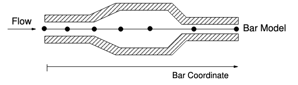
Fig. 4.15 Schematic of an advective bar
4.4.4.1. Using an Advective Bar as a Convective Flux BC
Use of the advective bar model requires that it be referenced by name in a
Convective Flux Boundary Condition along with the corresponding named Heat
Transfer Coefficient Correlation. Below shows a sample of an input deck that
uses an advective bar LIQUIDBAR with a corresponding heat transfer
correlation coefficient block CHANNEL to define a pair of convective flux
boundary conditions, CONV1 and CONV2.
BEGIN ARIA REGION MY_REGION
  .
  BEGIN ADVECTIVE BAR NETWORK LIQUIDBAR
    .
  END ADVECTIVE BAR NETWORK LIQUIDBAR
  .
  BEGIN HEAT TRANSFER CORRELATION COEFFICIENT CHANNEL
    .
  END HEAT TRANSFER CORRELATION COEFFICIENT CHANNEL
  .
  BEGIN CONVECTIVE FLUX BOUNDARY CONDITION CONV1
    .
  END CONVECTIVE FLUX BOUNDARY CONDITION CONV1

  BEGIN CONVECTIVE FLUX BOUNDARY CONDITION CONV2
    .
  END CONVECTIVE FLUX BOUNDARY CONDITION CONV2
.
END
Advective Bar Equation discusses the
formulation of the advective bar equations.
Fig. 4.16 shows a schematic of an advective bar
block, labeled Block_3 (black), set up between two volumetric blocks,
Block_1 (red) and Block_2 (green). The surfaces that are coupled to the
advective bar block are Surface_1 (boxed in the red dashed line) and
Surface_2 (boxed in the green dashed line), which belong to Block_1 and
Block_2 respectively. In addition, a nodelist is Nodelist_1 is defined
and contains only the left-most node in the advective bar block.
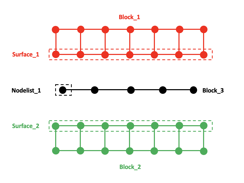
Fig. 4.16 Schematic of an advective bar block set up between two mesh blocks
Defining an advective bar requires various line commands in the aria material block as well as individual region-level commands. An example of declaring a typical advective bar block for the Schematic shown in Fig. 4.16 is given in the following. We first declare functions that will represent the wetted perimeter and bar area at the Sierra scope. We will also define an Aria material that will be assigned to the bar block:
BEGIN DEFINITION FOR FUNCTION AREA_FUNC
  TYPE = PIECEWISE LINEAR
  BEGIN VALUES
     0.0 1.0
    10.0 1.0
  END VALUES
END DEFINITION FOR FUNCTION AREA_FUNC

BEGIN DEFINITION FOR FUNCTION WETTED_PERIM_FUNC
  TYPE = PIECEWISE LINEAR
  BEGIN VALUES
     0.0  0.5
    10.0  0.5
  END VALUES
END DEFINITION FOR FUNCTION WETTED_PERIM_FUNC

BEGIN ARIA MATERIAL WATER
  .
  ADVECTION VELOCITY = BAR
  BAR AREA = USER_FUNCTION NAME = AREA_FUNC X = BAR_COORDINATE
  DENSITY = constant rho = 1000.0
  .
END ARIA MATERIAL WATER

BEGIN FINITE ELEMENT MODEL FEM
  .
  USE MATERIAL WATER FOR BLOCK_3
  .
END
The advection velocity for the bar material WATER must be defined as
ADVECTION VELOCITY = BAR. This advection velocity will be used for the bar
energy (and possibly momentum) equation. The advective bar command block along
with the bar energy equation are defined as follows:
BEGIN ARIA REGION MY_REGION
  BEGIN EQUATION SYSTEM ENERGY
    .
    EQ ENERGY FOR TEMPERATURE ON BLOCK_3 USING Q1 WITH DIFF LUMPED_MASS ADV SUPG
    ADVECTION VELOCITY FOR ENERGY = ADVECTION_VELOCITY
    .
    BEGIN ADVECTIVE BAR NETWORK LIQUIDBAR
      .
      ADD VOLUME BLOCK_3
      MASS FLOW RATE AT NODELIST_1 = 100.0 # KG/SEC^2
      FLUID DENSITY = 1000.0
      FLOW CROSS SECTION AREA FUNCTION = AREA_FUNC
      WETTED PERIMETER FUNCTION = WETTED_PERIM_FUNC
      .
    END ADVECTIVE BAR NETWORK LIQUIDBAR
  .
  END
END ARIA REGION MY_REGION
In the above, the advective bar area and density is defined under both the Aria
material WATER and advective bar network LIQUIDBAR. The reason why this
is done is discussed in Current Discrepancies with Advective Bars.
The nodelist block block_3 is added to the simulation as an advective bar.
For the above command block, the fluid density and fluid cross section area are
declared as constants. The leftmost node on the advective bar (nodelist_1)
is assigned a mass flow rate. A HEAT TRANSFER CORRELATION COEFFICIENT block is
declared under the same equation system (ENERGY for this example), labeled
CHANNEL:
BEGIN HEAT TRANSFER CORRELATION COEFFICIENT CHANNEL
  LAMINAR CORRELATION = TYPE 1
  TURBULENT CORRELATION = TYPE 74
  TRANSITION REYNOLDS NUMBER = 3000.
  COMPUTE REYNOLDS NUMBER
  COMPUTE PRANDTL NUMBER
  COMPUTE CHARACTERISTIC LENGTH MODEL = HYDRAULIC DIAMETER
  COMPUTE FRICTION FACTOR MODEL = SMOOTH TUBE
  COMPUTE ANNULUS DIAMETER RATIO
END
The HEAT TRANSFER CORRELATION COEFFICIENT defines a Nusselt Number ( ) which
is used to compute the heat transfer correlation coefficient (Eq.
(3.80)). The above declaration uses a fully developed laminar flow
with an analytical for the laminar region and a Gnielinski-type
correlation for annular flow with a friction factor in the turbulent regime.
The details of declaring the above command block can be found in Correlation Heat Transfer Coefficient. Convective boundary conditions, labeled
) which
is used to compute the heat transfer correlation coefficient (Eq.
(3.80)). The above declaration uses a fully developed laminar flow
with an analytical for the laminar region and a Gnielinski-type
correlation for annular flow with a friction factor in the turbulent regime.
The details of declaring the above command block can be found in Correlation Heat Transfer Coefficient. Convective boundary conditions, labeled
CONV1 and CONV2 are defined for surfaces surface_1 and
surface_2 in Fig. 4.16, respectively:
BEGIN CONVECTIVE FLUX BOUNDARY CONDITION CONV1
  ADD SURFACE Surface_1
  USE CORRELATION CONVECTION MODEL CHANNEL
  USE ADVECTIVE BAR LIQUIDBAR
END CONVECTIVE FLUX BOUNDARY CONDITION CONV1

BEGIN CONVECTIVE FLUX BOUNDARY CONDITION CONV2
  ADD SURFACE Surface_2
  USE CORRELATION CONVECTION MODEL CHANNEL
  USE ADVECTIVE BAR LIQUIDBAR
END CONVECTIVE FLUX BOUNDARY CONDITION CONV2
Alternatively, a single line command can be used in place of the above command block:
BC BAR_FLUX FOR ENERGY ON Surface_1 = GENERALIZED_NAT_CONV BAR=LIQUIDBAR HCORR = CHANNEL
BC BAR_FLUX FOR ENERGY ON Surface_2 = GENERALIZED_NAT_CONV BAR=LIQUIDBAR HCORR = CHANNEL
It should be noted that the above advective bar commands can also be coupled to
other energy EQ types, such as POROUS_ENTHALPY.
A bar model coordinate system facilitates user specification of the flow section properties. Here the bar coordinate system can be aligned with one of a Cartesian coordinate X,Y,Z directions. Optional use of an S coordinate system tied directly to the bar discretization enables modeling of flow along a circuitous path. Entrance length effects are supported for a limited number of empirical correlations. By default, influence of the entrance length effect is aligned with the bar model coordinates. Cases in which these effects are significant only over a portion of the flow can be modeled using an offset of the bar model coordinate (a schematic of this is shown in Fig. 4.17).
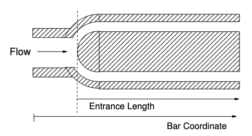
Fig. 4.17 Schematic of entrance length w.r.t bar coordinates
Advective Bar contains details about available commands for declaring advective bars.
Beta Capability
BAR MOMENTUM EQUATION is a beta feature and requires use of the –beta flag. This capability is not thoroughly tested and should be used with caution. Refer to Current Discrepancies with Advective Bars for proper usage.
4.4.4.2. Pressure Solve for Advective Bars
The pressure can be solved over the advective bar when requested. This is done by defining an equation system for the bar block:
BEGIN EQUATION SYSTEM Pressure
  .
  EQ BAR_MOMENTUM FOR PRESSURE ON BLOCK_3 USING Q1 WITH ADV SRC
  SOURCE FOR BAR_MOMENTUM ON BLOCK_3 = MAJOR_LOSS
  ADVECTION VELOCITY FOR BAR_MOMENTUM = ADVECTION_VELOCITY
  BC DIRICHLET FOR PRESSURE ON NODELIST_1 = CONSTANT VALUE = 0.0
  .
END
The individual terms ADV and SRC are defined in Advective Bar Pressure.
A MAJOR_LOSS source term is defined, which is the Darcy-Weisbach equation
for modeling head loss due to friction (Eq. (3.86)). Because
of this, we need to define a friction factor model in the Aria material block as
well:
BEGIN ARIA MATERIAL WATER
  .
  FRICTION FACTOR = HALAAND ROUGHNESS = 3.0E-5
  .
END ARIA MATERIAL WATER
A list of Aria material friction factors can be found in Friction Factor.
It should be noted that these
friction factors are used separately from the HEAT TRANSFER CORRELATION COEFFICIENT
computed friction factors; their discrepancies are discussed in
Current Discrepancies with Advective Bars.
4.4.4.3. Current Discrepancies with Advective Bars
The following presents some discrepancies with defining advective bars that users should be aware of; these discrepancies will be resolved in time. Currently the advective bar command block is defined as follows within the Aria region scope:
BEGIN ADVECTIVE BAR NETWORK LIQUIDBAR
  .
  ADD VOLUME BLOCK_3
  MASS FLOW RATE AT NODELIST_1 = 100.0 # KG/SEC^2
  FLUID DENSITY = 1000.0
  FLOW CROSS SECTIONAL AREA FUNCTION = AREA_FUNC
  WETTED PERIMETER FUNCTION = WETTED_PERIM_FUNC
  .
END ADVECTIVE BAR NETWORK LIQUIDBAR
The fluid density and the bar area must be repeated in the Aria materials block assigned to the bar:
BEGIN ARIA MATERIAL WATER
  .
  BAR AREA = USER_FUNCTION NAME = AREA_FUNC X = BAR_COORDINATE
  DENSITY = constant rho = 1000.0
  .
END ARIA MATERIAL WATER

BEGIN FINITE ELEMENT MODEL FEM
  .
  USE MATERIAL WATER FOR BLOCK_3
  .
END
Each of these two duplicate parameters (bar area and density) are used for
separate purposes; the FLUID DENSITY and FLOW CROSS SECTIONAL AREA
FUNCTION under the advective bar command block are used for computing the
nodal bar velocity vector output (default name is BAR_VELOCITY) or
imposing a mass flow rate over the bar from a velocity boundary condition. The
Aria material (WATER for our example) density and bar area is used to
compute the velocity at the bar element integration points (Eq.
(3.79)), which is used as the advecting velocity (default
name is ADVECTION_VELOCITY) in the bar energy (and momentum) equation. The
nodal BAR_VELOCITY is currently automatically provided, whereas the
integration point ADVECTION_VELOCITY must be postprocessed for visualization
(see Postprocessing). For cases where these properties differ (and some other corner cases with
sharp angular turns in the bar block) the BAR_VELOCITY and the postprocessed
ADVECTION_VELOCITY may differ. For visualization, it is recommended that
the user request the magnitude of the bar velocity vector, BAR_VELOCITY_MAG,
which can be postprocessed as an expression.
Additionally, the FLOW CROSS SECTIONAL AREA FUNCTION function under the
advective bar command block can be used to compute the hydraulic diameter by
using the WETTED PERIMETER FUNCTION for the HEAT TRANSFER CORRELATION COEFFICIENT
command block.
For computing the pressure via the BAR_MOMENTUM equation, a friction factor
must be defined at the Aria material level if the MAJOR LOSS source term
accounting for viscous effects is used:
BEGIN ARIA MATERIAL WATER
  .
  FRICTION FACTOR = HALAAND ROUGHNESS = 3.0E-5
  .
END ARIA MATERIAL WATER
In addition to this, a friction factor model is defined within HEAT TRANSFER CORRELATION COEFFICIENT
command blocks to compute a heat transfer coefficient:
BEGIN HEAT TRANSFER CORRELATION COEFFICIENT CHANNEL
  .
  COMPUTE FRICTION FACTOR MODEL = SMOOTH TUBE
  .
END
It should be noted that these friction factors are used for separate
computations. In the current implementation of the BAR_MOMENTUM equation,
only the HALAAND friction factor model can be defined with the
MAJOR_LOSS source term; if any other friction factor model is defined along
with a friction factor model under the HEAT TRANSFER CORRELATION COEFFICIENT
command block, then a parsing error will occur with the message being related to
multiple expression handles being defined for the friction factor.