Cubit 15.8 User Documentation
In addition to the commands discussed above, there are several other graphics system options in Cubit that can be controlled by the user.
They include:
Some shapes, such as cylinders, are drawn with silhouette lines; these lines don't represent true geometric curves, but help visualize the shape of a surface. Silhouette lines can be turned on or off with the command
Graphics Silhouette [On|Off]
The pattern used to draw silhouette lines can be set using the command
Graphics Silhouette Pattern [Solid | Dashdot | Dashed | Dotted | Dash_2dot | Dash_3dot | Long_dash | Phantom]
This option controls the width of the lines used in the wireframe, shaded, transparent, hiddenline and truehiddenline displays. The default is 1 pixel wide. The command to set the line width is
Graphics LineWidth <width_in_pixels>
This option controls the width of the lines used when highlighting an entity. Setting this to a width greater than the global line width often makes it easier to locate highlighted entities. If this setting has not been changed, the line width set in the command above is used. After using this command, it is necessary to refresh the graphics by either typing "display" or clicking the Refresh Graphics button. The command to set the highlighting line width is
Highlight LineWidth <width_in_pixels>
This option controls the size of text drawn in the graphics window. The size given in this command is the desired size relative to the default size. After using this command, it is necessary to refresh the graphics by either typing "display" or clicking the Refresh Graphics button. The command to set the text size is
Graphics Text Size <size>
This option controls the size of points drawn in the graphics window, such as vertices or heads of vectors; alternatively, the size of points representing nodes or vertices can be set independently of the global point size. The commands to set the point sizes are
Graphics Point Size <size>
Graphics [Node|Vertex] Point Size <size>
All graphics commands can be disabled or re-enabled with the command
Graphics {On|Off}
While graphics are off, changes in the model will not appear in the graphics window, and all graphics commands will be ignored. When graphics are again turned on, the scene will be updated to reflect the current state of the model.
A graphical scale can be drawn in the graphics window within the viewing area to obtain a bearing on model or part sizes. The command to turn the graphical scale on and off is:
Graphics Scale [On|Off]
The model axis may be drawn in the scene at the model origin. The axis is controlled with the command
Graphics Axis [Type <AXIS | Origin>] [On|Off]
The command is used to specify whether the model axis is visible, and to determine how the axis is drawn. If you include Type Axis , the axis will be drawn as three orthogonal lines; if you include Type Origin, the axis will be drawn as a circle at the model origin.
By default, an axis appears in the corner of the graphics window. This corner axis, also called the triad, can be disabled or re-enabled with the command
Graphics Triad [On | Off]
Many of the graphic options can be reset back to default values with the command:
Graphics Reset
The graphic options set to defaults are:
In addition, this command also:
The shrink graphics attribute allows you to view the elements shrunken about their centroid. This is useful for viewing 3D meshes, permitting viewing of interior elements. It may also be useful for visually inspecting the mesh for missing elements. To use the shrink option use:
graphics shrink <value>
draw hex <range>
draw tet <range>
etc...
where value is a number between 0 and 1. One (1) will shrink the elements to a point, while zero (0) will not shrink the elements. The following figures illustrate the effect of element shrink on a hex mesh.
Figure 1. Top: shrink=0.2, Bottom: shrink=0.5
The graphics tolerance commands change the way that facets are drawn in the graphics window. It does not affect the underlying geometry, just the graphics display. It can be useful to change the facet tolerance on large models if the refresh speed is slow.
Graphics Tolerance [ [ANGLE|Distance] <val>|Default ]
Specifying an angle will change the maximum allowable angle between neighboring facets. The distance option will set a maximum distance between adjacent facets. Increasing either of these numbers will result in coarser facets. The default option will return values to their default settings.
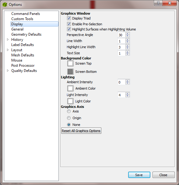
The GUI Options panel for manipulating these settings is found under Tools/Options and is shown below: