Cubit 15.2 User Documentation
This page describes the Sculpt application, a separate companion application to Cubit designed to run in parallel for generating all-hex meshes of complex geometry. Sculpt was developed as a separate application so that it can be run independently from Cubit on high performance computing platforms. It was also designed as a separable software library so it can be easily integrated as an in-situ meshing solution within other codes. As installed with Cubit, Sculpt can be set up and run directly from Cubit, in a batch process from the unix command line or from a user-defined input file. This documentation describes the input file and command line syntax for the Sculpt Application when running in batch mode. See this page for using Cubit to set up input for Sculpt. A brief technical description of Sculpt may also be found here.
Sculpt is currently built for windows, linux and mac operating systems. Current supported OS versions should be the same as those supported by Cubit. It is designed to take advantage of 64 bit multicore and distributed memory computers, using open-mpi as the basis for parallel communications.
Sculpt can be run using one of two excutables:
psculpt
mpiexec -np 8 psculpt -stl myfile.stl -cs 0.5
If appropriate system paths have not been set, you may need to use full paths when referring to mpiexec and psculpt.
sculpt
sculpt -j 8 -stl myfile.stl -cs 0.5If the -j option is not used, sculpt will default to a single processor for execution. The -mpi option can also be used with the sculpt application to indicate a specific mpi installation that is not included with CUBIT. For example:
sculpt -j 8 -mpi /path/to/mpiexec -stl myfile.stl -cs 0.5If the path specified by the -mpi option does not exist or the mpi version is incompatible, sculpt will attempt to use the local CUBIT-installed mpiexec or else the system mpiexec in the PATH environment.
Following is a listing of the available input commands to either sculpt or psculpt. When used from the unix command line, commands may be issued using the short form argument, designated with a single dash(-), or with the longer form, designated with two dashes (--). When used in an input file, only the long form may be used, omitting the two dashes (--)
    --help,              -h <args>   Displays Sculpt command documentation
    --num_procs,         -j <args>   Number of processors requested
    --input_file,        -i <args>   Input Parameter File
    --stl_file,          -stl <args> Input STL file
    --diatom_file,       -d <args>   Input Diatom description file
    --exodus_file,       -e <args>   Output Exodus file base name
    --volfrac_file,      -vf <args>  Output Volume Fraction file base name
    --input_vfrac,       -ivf <args> Input from Volume Fraction file base name
    --input_micro,       -ims <args> Input from Microstructure file base name
    --input_cart_exo,    -ice <args> Input from Cartesian Exodus file
    --input_spn,         -isp <args> Input from Microstructure spn file
    --nelx,              -x <args>   Num elements in x
    --nely,              -y <args>   Num elements in y
    --nelz,              -z <args>   Num elements in z
    --xmin,              -t <args>   Min x extent
    --ymin,              -u <args>   Min y extent
    --zmin,              -v <args>   Min z extent
    --xmax,              -q <args>   Max x extent
    --ymax,              -r <args>   Max y extent
    --zmax,              -s <args>   Max z extent
    --cell_size,         -cs <args>  Cell size (Num elements ignored)
    --stair,             -str <args> Don't fit boundary
    --align,             -a          Automatically align geometry to grid
    --smooth,            -S <args>   Smoothing method
    --csmooth,           -CS <args>  Curve smoothing method
    --laplacian_iters,   -LI <args>  Number of Laplacian smoothing iterations
    --max_opt_iters,     -OI <args>  Max. number of parallel Jacobi opt. iters
    --opt_threshold,     -OT <args>  Stopping criteria for Jacobi opt. smoothing
    --max_pcol_iters,    -CI <args>  Max. number of parallel coloring smooth iters
    --pcol_threshold,    -CT <args>  Stopping criteria for parallel color smooth
    --max_deg_iters,     -dgi <args> Maximum number of edge collapse iterations
    --deg_threshold,     -dg <args>  Convert hexes below threshold to degenerates
    --adapt_type,        -A <args>   Adaptive meshing type
    --adapt_threshold,   -AT <args>  Threshold for adaptive meshing
    --adapt_levels,      -AL <args>  Number of levels of adaptive refinement
    --mesh_void,         -V          Mesh void
    --gen_sidesets,      -SS <args>  Generate sidesets
    --htet,              -ht <args>  Convert hexes below quality threshold to tets
    --pillow,            -p <args>   Set pillow criteria (1=surfaces)
    --quality,           -Q          Dump quality metrics to file
    --debug_processor,   -D <args>   Sleep to attach to processor for debug
    --export_comm_maps,  -C          Export parallel comm maps to debug exo files
    --write_geom,        -G          Write geometry to sculpt.stl file (no mesh)
    --micro_expand,      -me <args>  Expand Microstructure grid by N layers
    --micro_shave,       -ms         Remove isolated cells at microstructure boundaries
    --capture,           -c <args>   Project to facet geometry
    --quiet,             -qt         Suppress output
    --print_input,       -pi         Print input values and defaults then stop
    --threads_process,   -tpp <args> Number of threads per process
    --version,           -vs         Print Sculpt version information and exit
    --iproc,             -ip  <args> Number of processors in I direction
    --jproc,             -jp  <args> Number of processors in J direction
    --kproc,             -kp  <args> Number of processors in K direction
--help, -h <args> Displays Sculpt command documentation
When used without arguments, this option will display a full list of all available commands that can be used with Sculpt. When used with one or more arguments, documentation on a specific command will be displayed. The "all" argument may be used to display the complete documentation for all commands.
--num_procs, -j <args> Number of processors requested
The number of processors that Sculpt will use to generate the mesh. The Cartesian domain will be divided into roughly equal sizes based on this value and the mesh for each portion of the domain generated independently. Continuity across processor boundaries is maintained with MPI (Message Passing Interface). Each processor will write a separate Exodus II file to disk containing its portion of the domain. The Sandia SEACAS tool, "EPU" can be used to join parallel files into a single file.
If not specified on the command line, the number of processors used will be 1. Also note that the num_procs argument cannot be used from within an input file. Instead it must be used from the command line.
For additional control on the arrangement of processor domains see arguments iproc, jproc, kproc
--input_file, -i <args> Input Parameter File
Rather than specifying a complicated series of arguments on the command line, an input file may also be used. An input file is a simple text file containing all arguments and parameters to be used in the current sculpt run. Input files are normally expected to have a ".i" extension. Arguments used in the input file are limited to the Long Names indicated for each command.
User comments can also be made anywhere in the file but must follow a "$" sign. The argument assignments that are intended to be read must be contained within a "begin sculpt" and "end sculpt" block. All arguments may use upper or lower case and can optionally use "=" between the command and its parameter. The following is an example input file:
   BEGIN SCULPT
     stl_file = "mygeom.stl"
     cell_size = 0.5
     exodus_file = "mymesh"
     mesh_void = true  $TRUE or ON is optional for this command
   END SCULPT
The following is an example of using an input file with sculpt:
sculpt -j 4 -i myinput.i
Note that the number of processors (-j) should always be used on the command line and cannot be included in the input file. Relative or absolute paths for files may also be used.
--stl_file, -stl <args> Input STL file
File name of a single STL (facet geometry) file to be used as input. Either an stl_file or diatom_file designation must be included to run Sculpt.
--diatom_file, -d <args> Input Diatom description file
File name of a diatom file to be used as input to Sculpt. Both stl_file and diatom_file cannot be used simultaneously. A diatom file is a constructive solid geometry description containing primitives for generating a full geometric definition of the model. Diatoms are commonly used as input to Sandia's CTH and Alegra codes. Multiple STL files can also be defined in a Diatom file.
--exodus_file, -e <args> Output Exodus file base name
The base file name of the resulting exodus mesh. Exodus files will be in the form <exodus_file>.e.<nproc>.<iproc>. For example, if the number of processors used is 3 and the exodus_file argument is "model", the following files would be written:
--volfrac_file, -vf <args> Output Volume Fraction file base name
Optionally generate exodus files containing a hex mesh of the Cartesian grid containing volume fraction data as element variables. If not specified, no volume fraction data files will be generated.
--input_vfrac, -ivf <args> Input from Volume Fraction file base name
Sculpt can optionally take an exodus file containing volume fraction data stored as element variables. Normally the exodus file has initially been written using the --volfrac_file (-vf) option. Since the exodus file will be a Cartesian grid spread accross multiple processors, the base filename for the parallel series of exodus files is used as the argument for this command. The input volume fraction file(s) would be used instead of an STL or diatom file. Since computing volume fractions from geometry can be time consuming, precomputing the volume fractions and reading them from a file can be advantageous if multiple meshes are to be generated from the same volume fraction data.
--input_micro, -ims <args> Input from Microstructure file base name
A microstructure file is an ascii text file containing volume fraction data for each cell of a Cartesian grid. The format for this file includes header information followed by data for each cell. The following is an example:
    TITLE = triple line system
    VARIABLES = x y z, phi_1, phi_2, phi_3
    ZONE i = 2 , j = 2 , k = 2
    0.0000       0.0000       0.0000      0.5000      0.5000      0.0000
    1.0000       0.0000       0.0000      0.3333      0.3333      0.3334
    0.0000       1.0000       0.0000      1.0000      0.0000      0.0000
    1.0000       1.0000       0.0000      0.0000      1.0000      0.0000
    0.0000       0.0000       1.0000      0.2000      0.4000      0.4000
    1.0000       0.0000       1.0000      0.6000      0.1000      0.3000
    0.0000       1.0000       1.0000      0.0000      0.0000      1.0000
    1.0000       1.0000       1.0000      0.9000      0.0000      0.1000
The header information should contain the following:
TITLE: any descriptive character string
VARIABLES: a list of variables separated by spaces or commas. It should include x, y, z as the first three variable names. The remaining names are arbitrary. The number of variable names listed must correspond to the number of data values for each cell of the Cartesian grid.
ZONE: Specify the number of cells in the i, j and k directions (corresponding to x, y, and z respectively)
The body of the file will contain one line per cell of the grid. The first three values correspond to the centroid location of a cell in the grid. The remaining values represent volume fractions for the cell for each variable listed. The sum of the volume fractions for each individual cell should be 1.0
Currently this format assumes that cell sizes are exactly 1.0 x 1.0 x 1.0 and the minimum cell centroid location is always 0.0, 0.0, 0.0. This results in a Cartesian grid with minimum coordinate = (-0.5, -0.5, -0.5) and maximum coordinate = (i-0.5, j-0.5, k-0.5)
Example usage of this command is as follows:
sculpt -j 8 -ims my_micro_file.tec -p 1
Smoothing: Sculpt will set automatic defaults for smoothing if user options have not been defined. These include:
--smooth 9 (surface smoothing option - no surface projection)
--csmooth 5 (curve smoothing option - hermite interpolation)
These options will generally provide a smoother curve and surface represention but may not adhere strictly to the volume fraction geometric definition. To over-ride the defaults, consider using the following options:
--smooth 8 (surface smoothing option - projection to interpolated surface)
--csmooth 2 (curve smoothing option - projection to interpolated curve)
Pillowing: For most 3D models it is recommended using pillowing since triple junctions (curves with at least 3 adjacent materials) will typically be defined where malformed hex elements would otherwise be generated. Surface pillowing (option 1) is usually sufficient to remove poor quality elements at triple junctions.
Boundary Conditions: Exactly seven nodesets will automatically be generated with this command. Each nodeset will contain the set of nodes corresponding to the following criteria:
    Nodeset ID         Contains nodes
        1              on minimum X domain boundary
        2              on maximum X domain boundary
        3              on minimum Y domain boundary
        4              on maximum Y domain boundary
        5              on minimum Z domain boundary
        6              on maximum Z domain boundary
        7              at all interior triple junctions
--input_cart_exo, -ice <args> Input from Cartesian Exodus file
An exodus mesh containing a Cartesian grid of elements can also be used as the source of a sculpt mesh. For this option the following conditions must be met:
Provided these conditions are met, sculpt will treat each block as a separate material and generate a smooth conforming mesh between the materials. This option is useful for converting a stair-step mesh into a smooth conforming mesh. The resulting sculpt mesh will have the same dimensions as the original exodus mesh, but will add layers of hexes at material interfaces. Example usage of this command is as follows:
sculpt -j 8 -ice my_cartesian_file.e -p 1
Smoothing: Sculpt will set automatic defaults for smoothing if user options have not been defined. These include:
--smooth 9 (surface smoothing option - no surface projection)
--csmooth 5 (curve smoothing option - hermite interpolation)
These options will generally provide a smoother curve and surface represention but may not adhere strictly to the volume fraction geometric definition. To over-ride the defaults, consider using the following options:
--smooth 8 (surface smoothing option - projection to interpolated surface)
--csmooth 2 (curve smoothing option - projection to interpolated curve)
Pillowing: For most 3D models it is recommended using pillowing since triple junctions (curves with at least 3 adjacent materials) will typically be defined where malformed hex elements would otherwise be generated. Surface pillowing (option 1) is usually sufficient to remove poor quality elements at triple junctions.
Boundary Conditions: Exactly seven nodesets will automatically be generated with this command. Each nodeset will contain the set of nodes corresponding to the following criteria:
    Nodeset ID         Contains nodes
        1              on minimum X domain boundary
        2              on maximum X domain boundary
        3              on minimum Y domain boundary
        4              on maximum Y domain boundary
        5              on minimum Z domain boundary
        6              on maximum Z domain boundary
        7              at all interior triple junctions
--input_spn, -isp <args> Input from Microstructure spn file
--input_spn, -isp <args> Input from Microstructure spn file
A .spn file is an optional method for importing volume fraction data into sculpt for meshing. This format is a simple ascii text file containing one integer per cell of a Cartesian grid. Each integer represents a unique material identifier. Any number of materials may be used, however for practical purposes, the number of unique materials should not exceed more than about 50 for reasonable performance. An example file containing a 3 x 3 x 3 grid with 2 materials may be defined as follows:
    1 1 2 1 2 1 1 1 1
    1 2 2 1 2 2 1 1 2
    2 1 1 1 2 1 1 2 2
Any unique integer may be used to identify a material. All cells with the same ID will be defined as a continuous block with the same exodus block ID in the final mesh. All integers should be separated by a space or newline. The number of integers in the file should exactly correspond to the size of the Cartesian grid. The dimensions of the Cartesian grid must be specified on the command line as part of the input. The following is an example:
sculpt -j 8 -x 10 -y 24 -z 15 -isp "my_spn_file.spn" -p 1
The order of the cells in the input file will be read according to the following schema:
    for (i=0; i<nx; i++)
      for (j=0; j<ny; j++)
        for (k=0; k<nz; k++)
          // read next value from file
Where nx, ny, nz are the number of cells in each Cartesian direction. The initial size of the Cartesian grid will be exactly nx X ny X nz with the minimum coordinate at (0.0, 0.0, 0.0)
Smoothing: Sculpt will set automatic defaults for smoothing if user options have not been defined. These include:
--smooth 9 (surface smoothing option - no surface projection)
--csmooth 5 (curve smoothing option - hermite interpolation)
These options will generally provide a smoother curve and surface represention but may not adhere strictly to the volume fraction geometric definition. To over-ride the defaults, consider using the following options:
--smooth 8 (surface smoothing option - projection to interpolated surface)
--csmooth 2 (curve smoothing option - projection to interpolated curve)
Pillowing: For most 3D models it is recommended using pillowing since triple junctions (curves with at least 3 adjacent materials) will typically be defined where malformed hex elements would otherwise be generated. Surface pillowing (option 1) is usually sufficient to remove poor quality elements at triple junctions.
Boundary Conditions: Exactly seven nodesets will automatically be generated with this command. Each nodeset will contain the set of nodes corresponding to the following criteria:
    Nodeset ID         Contains nodes
        1              on minimum X domain boundary
        2              on maximum X domain boundary
        3              on minimum Y domain boundary
        4              on maximum Y domain boundary
        5              on minimum Z domain boundary
        6              on maximum Z domain boundary
        7              at all interior triple junctions
    --nelx,              -x <args>   Num elements in x
    --nely,              -y <args>   Num elements in y
    --nelz,              -z <args>   Num elements in z
Defines the number of intervals in x, y, and z directions respectively of the base Cartesian grid used for defining the volume fraction definition and meshing. For best results the intervals specified should result in approximately equilateral cells.
    --xmin,              -t <args>   Min x extent
    --ymin,              -u <args>   Min y extent
    --zmin,              -v <args>   Min z extent
    --xmax,              -q <args>   Max x extent
    --ymax,              -r <args>   Max y extent
    --zmax,              -s <args>   Max z extent
Defines the bounding box or range of the Cartesian mesh to be used for meshing
--cell_size, -cs <args> Cell size (Num elements ignored)
Defines a target edge size for the cells of the base Cartesian grid. Both interval and cell_size cannot be specified simultaneously. If cell_size is used without a range specification, a bounding box of the geometry will be computed and used as the default range.
--stair, -str <args> Don't fit boundary
The stair option generates a stair-step mesh where the cells of the Cartesian grid are used in the final mesh without projection or smoothing to the material interfaces. Cells selected from the Cartesian grid to be used in the final mesh will have volume fraction greater than 0.5. Several different options for the stair argument are available:
Note: The stair-step option currently does not support generation of sidesets. The -SS or --gen_sidesets option will be ignored when using the stair option.
--align, -a Automatically align geometry to grid
The align option will attempt to orient the Cartesian grid with the main dimensions of the geometry. This is done by defining a tight bounding box around the geometry using an optimization procedure where the objective is to minimize the difference in volume between an enclosing box and the geometry. Using the align command will override any bounding box parameters previously entered and will build an "aligned" bounding box around the full geometry. It is currently only implemented for STL geometry and will ignore any other diatom definitions. Note that this option will also write temporary stl and diatom files to the working directory.
--smooth, -S <args> Smoothing method
Automatic adjustment of node locations following meshing to improve element quality. The default smooth options in most cases should be sufficient, however in some cases it may be worthwhile to experiment with different smoothing methods. The surface smoothing options available are: (Default is 1)
--csmooth, -CS <args> Curve smoothing method
The csmooth option controls the smoothing method used on curves. In most cases the default should be sufficient, however it may be useful to experiment with different options. The default curve smoothing option is 5 (Volume Fraction). The following curve smoothing options are available:
--laplacian_iters, -LI <args> Number of Laplacian smoothing iterations
Number of Laplacian smoothing iterations performed when Hybrid smoothing option is used. See Laplacian Smoothing Default value is 2.
--max_opt_iters, -OI <args> Maximum number of opt. smoothing iterations to perform
Indicates the maximum number of iterations of optimization-based smoothing to perform. May complete sooner if no further improvement can be made. See Optimization Smoothing
--opt_threshold, -OT <args> Stopping criteria for Jacobi opt. smoothing
Indicates the value for scaled Jacobian where Optimization smoothing will be performed. Elements with scaled Jacobian less than opt_threshold and their neighbors will be smoothed. Default value is 0.60.
--max_pcol_iters, -CI <args> Max. number of parallel coloring smooth iters
Maximum number of spot smoothing (also known as parallel coloring) iterations to perform. May complete sooner if no further improvement can be made. See Spot Optimization. Default is 100.
--pcol_threshold, -CT <args> Stopping criteria for parallel color smooth
Indicates scaled Jacobian threshold for spot smoothing (also known as parallel coloring). A parallel coloring algorithm is used to uniquely identify and isolate nodes to be improved using optimization. Default is 0.2
--max_deg_iters, -dgi <args> Maximum number of edge collapse iterations
Maximum number of edge collapse iterations to perform to create degenerate hex elements. See Creating degenerate hexes. Default is -1.
--deg_threshold, -dg <args> Maximum number of edge collapse iterations
Indicates scaled Jacobian threshold for edge collapses. Nodes at hexes below this threshold will be candidates for edge collapses, provided doing so will improve the minimum scaled Jacobian at the neighboring hexes. Default is 0.
--adapt_type, -A <args> Adaptive meshing type
This option will automatically refine the mesh according to a user-defined criteria. Without this option, a constant cell size will be assumed everywhere in the model. To build the mesh, Sculpt uses an approximation to the exact geometry of the CAD model by interpolating mesh surfaces from volume fraction samples in each cell of the Cartesian grid. In general, the, higher the resolution of the Cartesian grid, the more sampling is done and the more accurate the mesh will represent the initial geometry. The adapt_type selected will control the criteria used for refining the mesh. If the criteria is not satisfied, the refinement will continue until a threshold indicated by the adapt_threshold parameter is satisfied everywhere, or the maximum number of levels (adapt_levels) is reached. The following criteria for refinement are available:
To maintain a conforming mesh, transition elements will be inserted to transition between smaller and larger element sizes. Default for the adapt_type option is 0 (or that no adaptive refinement will take place).
In all cases the initial Cartesian grid defined by xint, yint and zint or the cell_size value will be used as the basis for refinement and will define the approximate largest element size in the mesh.
--adapt_threshold, -AT <args> Adaptive threshold value
This value controls the sensitivity of of the adaptivity. The value used should be based upon the adapt_type:
adapt_threshold = 0.25 * cell_size / adapt_levels^2
Note that the user defined adapt_threshold may not be satisfied everywhere in the mesh if the value defined for adapt_levels is exceeded.
--adapt_levels, -AL <args> Max Adaptive Levels
The maximum number of levels of adaptive refinement to be performed. One level of refinement will split each Cartesian grid cell identified for uniform refinement into eight child cells. Two levels of refinement will split each cell again into eight, resulting in sixty-four child cells, three levels into 256, and so on. The maximum number of subdivision per cell is give as:
number of cells = 8^adapt_levels
The minimum edge length for any cell will be given by:
min cell edge length = cell_size / adapt_levels^2
The actual number of refinement levels used will be determined by whether all cells meet the adapt_threshold, or the adapt_levels value is exceeded. The default adapt_levels is 2. Note that setting the adapt_levels more than 4 or 5 can result in long compute times.
--mesh_void, -V Mesh void
If mesh_void option is used, then the void space surrounding the geometry will be treated as a separate material. Elements will be generated in the void to the extent of the Cartesian grid boundaries.
--gen_sidesets, -SS <args> Generate sidesets
Several options for generating sidesets are available. Indicate which option to use with integer 1 to 4
         surface 1
           0 1 2 3 4 5 6 7 8 9
           10 11 12 13 14 15 16 17 18 19
           20 21 22 23
         endsurface 1
The id following the surface designation will be used as the sideset ID. Up to 10 triangle IDs, per line may be assigned to the surface. Triangle IDs are assigned based on order they appear in the STL file. Any number of surfaces may be defined. For this option, the assumption is that all triangles included in the STL files will be included in at least one surface designation.
--htet, -ht <args> Convert hexes below quality threshold to tets
Automatically generate tets in place of poor quality elements. This option can be used to eliminate poor quality hex element by replacing each hex that falls below the user defined Scaled Jacobian with 24 tets. Default value for htet is -1.0. The result will be a non-conforming mesh at the interface between tets and hexes. One additional nodeset and sideset will be generated and output to the exodus file if the sideset option is specified.
Sideset 10000 = the set of hex faces that interface a set of 4 tets.
Nodeset 1000 = the set of nodes at the interface between hexes and tets. One node per face in Sideset 10000 will be included.
--pillow, -p <args> Set pillow criteria (1=surfaces)
Generate a pillow or additional layer of hexes at surfaces as a means to improve element quality near curve interfaces. This is intended to elimate the problem of 3 or more nodes from a single hex face lying on the same curve. The following options are available:
These options may be modified by adding 2 additional digits to the option. The second digit will turn on and off smoothing following the pillow operation and the third digit defines the number of layers of quads beyond the poor quality quads at the curves that will be included in the pillow region. For example:
--quality, -Q Dump quality metrics to file
A file named "quality.csv" will be created in the current working directory (or appended). Quality metrics and other details of the run will be written to this file. This option is currently on by default.
--debug_processor, -D <args> Sleep to attach to processor for debug
Used for debugging. All processes will sleep until the designated process is attached to a debugger.
--export_comm_maps, -C Export parallel comm maps to debug exo files
Used for debugging and verification. Exodus files of the mesh containing the communication nodes and faces at processor boundaries will be written as nodes and side sets. This provides a way to visually check the validity of the parallel communication maps.
--write_geom, -G Write geometry to sculpt.stl file (no mesh)
The geometry generated by sculpt can be exported as an stl file called "sculpt.stl". Prior to generating the mesh, Sculpt defines a temporary facet-based geometry description of the boundaries of the model. This option will generate the facet-based geometry, dump it to the file "sculpt.stl", and then stop without generating the mesh. Additionally, one stl file per processor will be generated in the form "sculpt.stl.<n>.<j>", where <n> is the current processor number and <j> is the total number of processors used.
--micro_expand, -me <args> Expand Microstructure grid by N layers
This option expands the Cartesian grid by a specified number of layers. It can be used with any of the following input options:
In some cases the interior material interfaces may intersect the domain boundaries at small acute angles. When this occurs it may be difficult or impossible to achieve computable mesh quality at these intersections. To address this problem, one or more layers of hexes may be added to the Cartesian grid. The volume fractions from cells at the boundary are copied to generate additional layers. This has the effect of increasing the angle of intersection for any material interfaces intersecting the domain boundary. Usualy a value of 1 or 2 is sufficient to sufficiently improve quality.
Note that the resulting mesh in the expanded layers serves only to improve mesh quality and will only duplicate existing data at the boundaries. It may not reflect the actual material structure within the expansion layers.
--micro_shave, -ms <args> Remove isolated cells at microstructure boundaries
This option potentially modifies the outermost layer of Cartesian cells of a microstructures file. It will identify isolated cells where the assigned material is unique from all of its surrounding cells at the boundary. When this occurs, the cell material is reassigned to the dominant nearby material.
This option is useful if it is noted that a cell structure just barely grazes the exterior planar boundary surface. Poor quality elements can often result with this condition. The micro_shave option will, in effect, remove material from the cell structure, but will result in better quality elements by removing the intersection region with the boundary.
micro_shave can be used with any of the following input options:
--capture, -c <args> Project to facet geometry
This is an experimental option still in development. Following meshing and smoothing, sculpt will project nodes to the initial triangle facets defined in an initial STL input file. Node projection is based only on the closet facet, so features (curves) will not be honored. This option may however be useful for models that do not contain sharp features. The capture argument is currently limited to 0=off, 1=on.
--threads_process, -tpp <args> Number of threads per process
This option is currently experimental and under development. Sculpt may use shared memory parallelism to improve performance. When built with the Kokkos library, some algorithms in sculpt will use shared memory parallel threads in addition to MPI distributed memory parallelism (MPI+X). Currently this option is implemented only for surface and volume Laplacian smoothing algorithms. This option may not be available requiring a custom build of sculpt to be used. Check with developers if you would like to use this option.
--version, -vs Print Sculpt version information and exit
Prints Sculpt version information and exits.
    --iproc,             -ip  <args> Number of processors in I direction
    --jproc,             -jp  <args> Number of processors in J direction
    --kproc,             -kp  <args> Number of processors in K direction
Arguments iproc, jproc and kproc provide user control over the processor decomposition in I, J, and K directions respectively. iproc * jproc * kproc must equal the number of processors specified on the command line using the -j option.
--quiet, -qt Suppress output
Suppress any output to the command line from Sculpt as it is running.
--print_input, -pi Print input values and defaults then stop
Display all input parameters and defaults used in the current Sculpt run to the output window and then stop. No mesh (or volume fractions) will be generated.
The following illustrate simple use cases of the Sculpt application. To use these examples, copy the following stl and diatom files to your working directory
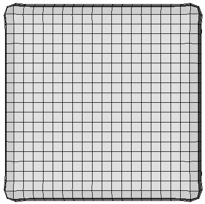
sculpt -j 4 -stl brick1.stl -cs 0.5
Runs sculpt with 4 processors with geometry input from brick1.stl. Uses a base Cartesian cell size of 0.5. The bounding box and all other parameters will be defaulted. The result should be the 4 exodus files:
     brick1.stl_results.e.4.0
     brick1.stl_results.e.4.1
     brick1.stl_results.e.4.2
     brick1.stl_results.e.4.3
These files can be combined into a single file using the SEACAS tool epu
epu -p 4 brick1.stl_results
The result of this operation should be a single file:
brick1.stl_results.e
To view the resulting mesh in Cubit, use the import free mesh command. For example:
Figure 1. Example 1 mesh
mpiexec -np 4 psculpt -x 46 -y 26 -z 26 -t -6.5 -u -6.5 -v -6.5 -q 16.5 -r 6.5 -s 6.50 -d bricks.diatom
In this case we use mpiexec to start 4 processes of psculpt. We explicitly define the number of Cartesian intervals and the dimensions of the grid. Rather than using the -stl option, we use the -d option which allows us to specify the diatom file, bricks.diatom. This file allows us to specify multiple stl files, where each one represents a different material. In this case we use both brick1.stl and brick2.stl, which are called out in bricks.diatom.
We can use similar commands as used in Example 1 to combine and import the free mesh into Cubit for display.
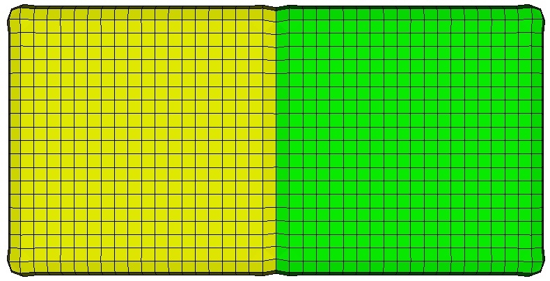
Figure 2. Example 2 mesh