Landfill 1 (RCRA Subtitle D)
Basic Soil Cover installed to meet minimum requirements for RCRA Subtitle D governed landfills. These requirements apply to municipal solid waste landfills (MSWL) to be closed using engineered covers and are designed with intent to meet the following performance objectives:
- cover permeability less than or equal to the permeability of the bottom liner/subsoil or no greater than 10-5 cm/sec;
- minimize infiltration using no less than 45 cm of soil; and
- minimize erosion using no less than 15 cm of topsoil for plant growth.
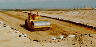
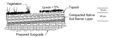
The installed test cover is 60 cm thick. It is constructed of two principal layers. The top vegetation layer is 15 cm of loosely laid topsoil. The bottom layer is a 45 cm thick compacted soil barrier layer. See figure below.
Landfill 2 (Geosynthetic Clay Liner)
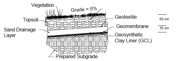
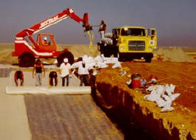
Geosynthetic Clay Liner (GCL) Cover is identical to the traditional Compacted Clay Cover with the exception that the expensive (Dwyer 1998) and problematic (Dwyer 2000) clay barrier layer was replaced with a manufactured sheet known as a GCL installed in its place. All other aspects of the cover were identical to those in Compacted Clay Cover. The overall thickness of this cover as-built was 90 cm. The covers component layers from bottom to top is the barrier layer (the GCL membrane covered with a geomembrane that comprises the composite barrier layer), 30 cm sand drainage layer, geotextile filter fabric, and 60 cm vegetation soil layer, respectively. The installed geomembrane also had eight 1-cm2 randomly placed defects in it similar to those inflicted on the Compacted Clay Covers geomembrane. See figure below.
The GCL installed is a product manufactured by Claymax. It consists of two non-woven fabrics that sandwich a thin layer of bentonite. The delivered-saturated hydraulic conductivity of the GCL per the manufacturer (Claymax 1995) was specified as 5 x 10⁻⁹ cm/sec.
Landfill 3 (RCRA Subtitle C)
Compacted Clay Cover designed and constructed in accordance with minimum regulatory requirements for closure of hazardous and mixed waste landfills. These regulations are somewhat vague. To overcome this vagueness, the Environmental Protection Agency (EPA) recommended a cover profile for the RCRA Subtitle C final cover design profile described below, from bottom layer to top layer:
- A composite barrier layer consisting of a minimum 60-cm thick layer of compacted natural or amended soil with a maximum saturated hydraulic conductivity of 1 x 10⁻⁷ cm/sec in intimate contact with a minimum 40-mil geomembrane overlying this soil layer.The function of this composite barrier layer is to limit downward moisture movement.
- A drainage layer consisting of a minimum 30-cm thick sand layer having a minimum saturated hydraulic conductivity of 1 x 10⁻² cm/sec, or a layer of geosynthetic material having the same characteristics;
- A top vegetation/soil layer consisting of a minimum 60-cm of soil graded at a slope between 3 and 5 percent with vegetation or an armored top surface.
The installed Compacted Clay Cover is 1.5 m thick which basically matches the recommended EPA design described above. The profile for this cover consists of three layers. See figure below.
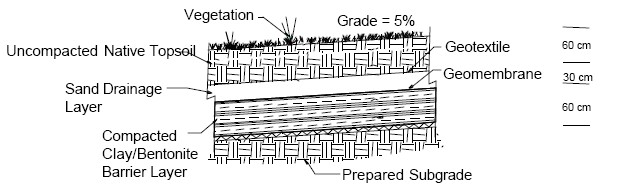
The bottom layer is a 60 cm thick compacted soil barrier layer. The native soil required amendment to meet the saturated hydraulic conductivity requirement (maximum of 1 x 10⁻⁷ cm/sec) for this barrier layer. Laboratory tests determined that a mixture of 6% by weight of sodium bentonite with the native soil compacted “wet of optimum” to a minimum of 98% of maximum dry density would be adequate.
A 40 mil linear low density polyethylene (LLDPE) geomembrane was placed directly on the compacted soil barrier layer to create a composite barrier layer. The purpose of this composite barrier layer is to create an impermeable barrier that blocks the infiltration of water. Eight 1-cm2 defects (puncture holes) were purposely and randomly placed in this geomembrane to be representative of a geomembrane installation with average quality control conditions (Dwyer et al. 1998).
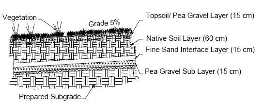
Landfill 4 (Ansiotropic Barrier)
The Anisotrropic Barrier is a capillary barrier system designed to limit the downward movement of water while encouraging the lateral movement of water. This cover is composed of a layering of capillary barriers.
The cover system contains four layers: (1) a top vegetation layer; (2) a cover soil layer; (3) an interface layer; and (4) a sublayer. The vegetation layer is 15 cm thick. It is comprised of a mixture of local topsoil and pea-gravel. The gravel to soil mixture ratio by weight was 0.25 (25%). The gravel was added to assist in minimizing surface erosion due to surface runoff. This layer encourages evapotranspiration, allows for vegetation growth, and reduced surface erosion. The cover native soil layer is 60 cm thick. Its function is to allow for water storage and eventual evapotranspiration and to serve as a rooting medium. The interface layer is 15 cm of fine sand that serves as a filter between the overlying soil and the underlying gravel, and serves as a drainage layer to laterally divert water to collection areas that has percolated through the cover soil. The sublayer is 15 cm of pea-gravel. The native soil overlying the sand layer create one capillary barrier while the sand overlying the pea gravel creates a second capillary break. See figure below.
Landfill 5 (Capillary Barrier)
This cover system consists of four primary layers from bottom to top: (1) a lower drainage layer; (2) a barrier soil layer; (3) an upper drainage layer; and (4) a topsoil layer. The barrier soil layer and lower drainage layer comprise the capillary barrier. The lower drainage layer is composed of 30 cm of washed concrete sand. See figure below.
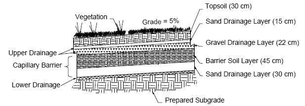
The 45 cm barrier soil layer was installed directly on the sand. The upper drainage layers were placed over the barrier soil layer. This upper drainage layer consists of two materials containing 22 cm of clean pea gravel and 15 cm of washed concrete sand. Finally, a 30 cm thick layer of topsoil was placed on the sand.
Landfill 6 (Evapotranspiration)
The ET Cover consists of a single, vegetated soil layer constructed to represent an optimum mix of soil texture, soil thickness, and vegetation cover. The installed test cover is a 105 cm thick monolithic soil cover. The bottom 90 cm of native soil was compacted while the top 15 cm of topsoil was loosely placed. The soil allows for water storage, which combined with the vegetation, is designed to optimize evapotranspiration. See figure below.
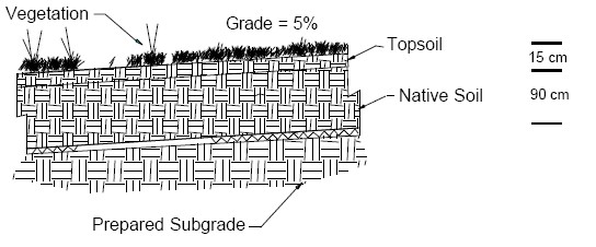
A thin gravel veneer (2 to 4 cm) was placed on the surface after the cover was seeded. The objective of the gravel veneer was to enhance the vegetation establishment and minimize erosion.
After the covers were constructed, they were drill-seeded with native rangeland vegetation. The seed mix was chosen based on an acceptable native vegetation that would provide an adequate coverage during both warm and cool growing seasons.