
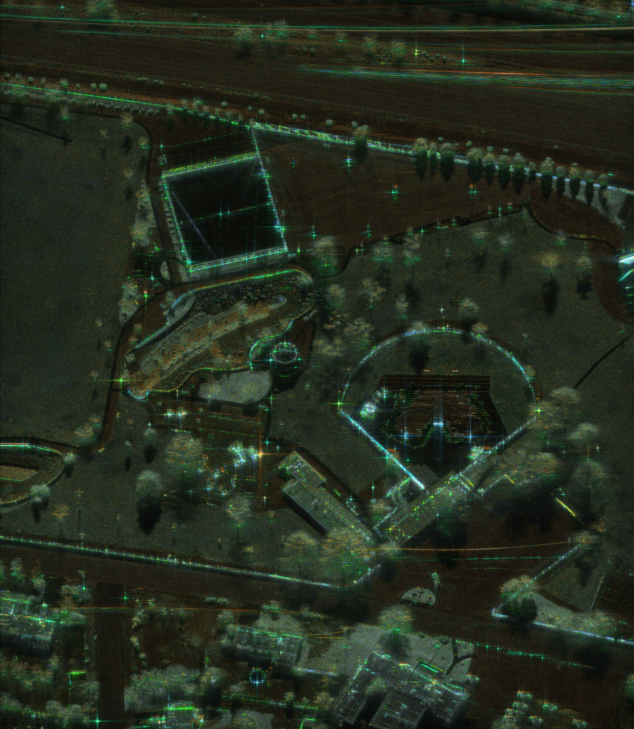
Sandia National Laboratories possesses extensive expertise in advanced radar systems, developing cutting-edge capabilities across various operational modes.
Our research and development efforts continually push the boundaries of what is possible in radar sensing, ensuring superior performance in complex environments and demonstrating Sandia’s leadership in radar innovation.
Featured Radar Modes
Synthetic Aperture Radar (SAR)
Synthetic Aperture Radar (SAR) is a highly versatile active sensing technology capable of capturing fine-resolution data through thick clouds, heavy rain, and complete darkness. The true power of SAR lies in its adaptability, driven by a combination of operating frequencies and dynamic imaging modes. By selecting different microwave frequency bands—such as high-frequency X-band for fine structural detail, mid-frequency C-band for general mapping, or low-frequency L-band for foliage and soil penetration—operators can peer through different layers of the environment. Combined with flexible imaging modes like Spotlight (which dwells on a specific target for maximum detail), and Stripmap (which captures a continuous, uniform swath), SAR provides a customizable toolkit for global monitoring. Explore the visuals below to see how these frequencies and beam-steering modes actively shape our view of the Earth.

USE
Single, known location to be imaged. Area fits within patch size limitations for the desired resolution.

FLIGHTPATH
Linear

FIELD OF REGARD (FOR)
Butterfly wings (dependent on resolution)
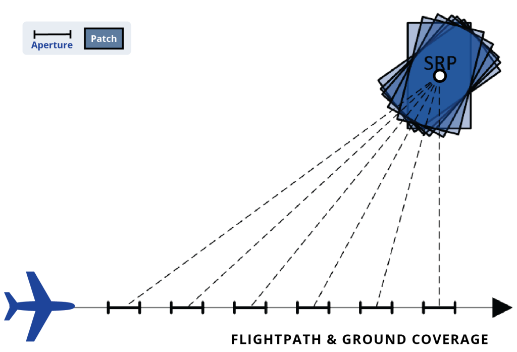


IMAGE SIZE
Primarily a function of resolution (due to processor limits; otherwise limited by the antenna beam footprint). Image size may vary from patch to patch.
RESOLUTION
Available in all resolutions. Resolution may be varied from patch to patch. Finer resolution leads to smaller area coverage on the ground.
IMAGE FORMATION
Continues until operator specified number of images reached, out of range, or stopped by operator.
VARIANTS
| AUTOPASS Assumes aircraft will continue to fly the same heading as when the command was received. Radar will continue to form images for as long as the SRP is in the FOR or operator stops the collection. Typically used for dynamic, real-time applications. |
| GUIDED (PLANNED) Aircraft is guided to achieve required flightpath. Typically used when executing a coherent change detection pass or when performing a data collection in which a predefined aircraft/SRP geometry is required. |
RELATED TO
- Class of Spot modes that use the same SRP for subsequent SAR images. Different flightpath geometries yield different capabilities for exploitation.

USE
Single, known location to be imaged. Area fits within patch size limitations for the desired resolution.

FLIGHTPATH
Arbitrary

FIELD OF REGARD (FOR)
Butterfly wings (dependent on resolution)
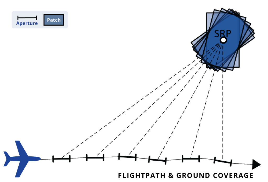
IMAGE SIZE
Primarily a function of resolution (due to processor limits; otherwise limited by the antenna beam footprint). Image size may vary from patch to patch.
RESOLUTION
Available in all resolutions. Resolution may be varied from patch to patch. Finer resolution leads to smaller area coverage on the ground.
IMAGE FORMATION
Continues until out of range or stopped by operator.
CONSTRAINTS
Arbitrary flightpath but extremely sharp turns can cause the mode to end prematurely.
RELATED TO
- Class of Spot modes that use the same SRP for subsequent SAR images. Different flightpath geometries yield different capabilities for exploitation.
USE
Single, known location to be imaged. Area fits within patch size limitations for the desired resolution.

FLIGHTPATH
Circular

FIELD OF REGARD (FOR)
Broadside line in butterfly wing FOR (dependent on resolution)
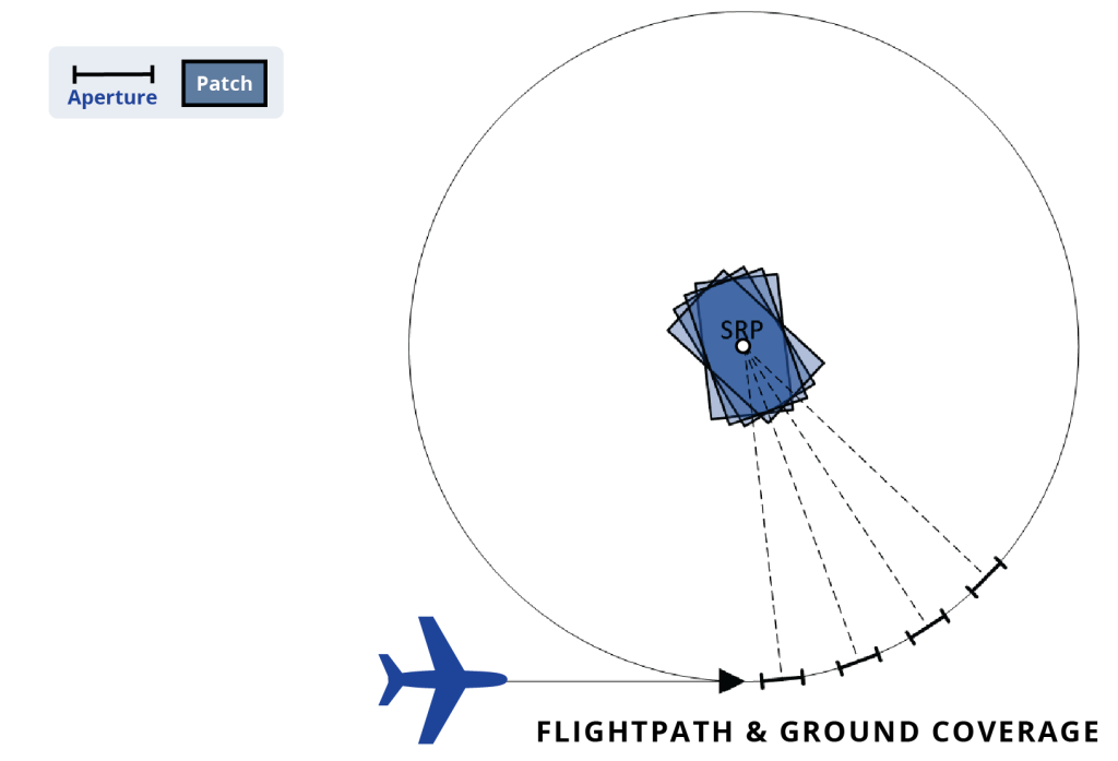
IMAGE SIZE
Primarily a function of resolution.
RESOLUTION
Available in all resolutions. Resolution may be varied from patch to patch. Finer resolutions lead to smaller area coverage on the ground and slower capture (and therefore fewer patches collected during each circle).
IMAGE FORMATION
Continues until operator specified number of images reached, SRP is out of range (e.g., due to leaving circular flightpath), or stopped by operator.
CONSTRAINTS
Variation in circle shape affects image quality; project requirements may impose additional flight constraints.
VARIANTS
| GUIDED (PLANNED) Aircraft is guided to achieve required flightpath. Typically used when executing a coherent change detection pass or when performing a data collection in which a predefined aircraft/SRP geometry is required. |
| AUTOPASS Radar puts the circle flightpath entry point directly ahead of the aircraft so that the mode starts as fast as possible. Radar will continue to form images for as long as the SRP is in the FOR or operator stops collection. Typically used for dynamic, near-real time applications. |
RELATED TO
- Class of Spot modes that use the same SRP for subsequent SAR images. Different flightpath geometries yield different capabilities for exploitation.
- When needing to view a target from all aspects, Spot Circle is more efficient than multiple Spotlight passes. Spot Circle also currently allows for better motion measure calibration between apertures than Video Circle.

USE
Single, known location to be imaged. Area fits within patch size limitations for the desired resolution. Desire to view phenomenology changes (e.g., slow-moving radar shadows) nearly continuously.

FLIGHTPATH
Linear

FIELD OF REGARD (FOR)
Butterfly wings (dependent on resolution)
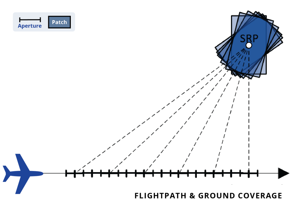
IMAGE SIZE
Primarily a function of resolution (due to processor limits; otherwise limited by the antenna beam footprint). Image size (number of pixels) must remain constant.
RESOLUTION
Available in all resolutions. Finer resolution leads to smaller area coverage on the ground. Motion compensation methodology can limit the finest resolution achievable. Azimuth resolution can be varied during post-processing.
FRAME RATE
Finer resolution or larger images lead to slower maximum possible frame rate. Radar can be configured to form images at a given constant frame rate or as fast as possible.
IMAGE FORMATION
Continues until pass ends, out of range, or stopped by operator.
CONSTRAINTS
Extended duration passes will lead to drift in motion measurement (imagery geolocation error).
VARIANTS
| AUTOPASS Assumes aircraft will continue to fly the same heading as when the command was received. Radar will continue to form images for as long as the SRP is in the FOR or operator stops collection. Typically used for dynamic, near-real time applications. |
| GUIDED (PLANNED) Aircraft is guided to achieve required flightpath. Typically used when executing a coherent change detection pass or when performing a data collection in which a predefined aircraft/SRP geometry is required. |
RELATED TO
- Class of Spot modes that use the same SRP for subsequent SAR images. Different flightpath geometries yield different capabilities for exploitation.
- Video Line is similar to Spotlight except it forms imagery at a much higher update rate since it uses overlapping apertures. Video modes better show slow moving radar shadows in images than static image modes.

USE
Single, known location to be imaged. Area fits within patch size limitations for the desired resolution. Desire to view phenomenology changes (e.g., slow-moving radar shadows) nearly continuously.

FLIGHTPATH
Circular

FIELD OF REGARD (FOR)
Broadside line in butterfly wing FOR (dependent on resolution)
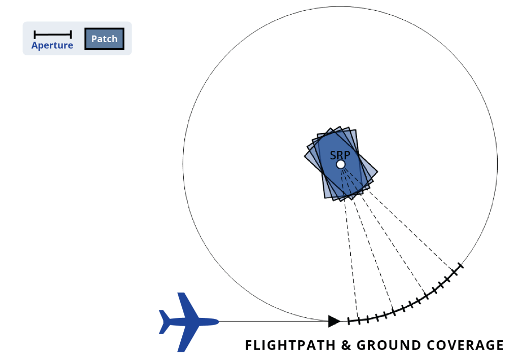
IMAGE SIZE
Primarily a function of resolution (due to processor limits; otherwise limited by the antenna beam footprint). Image size (number of pixels) must remain constant.
RESOLUTION
Available in all resolutions. Finer resolution leads to smaller area coverage on the ground.
FRAME RATE
Finer resolution or larger images lead to slower maximum possible frame rate. Radar can be configured to form images at a given constant frame rate or as fast as possible.
IMAGE FORMATION
Continues until pass ends, SRP is out of range (e.g., due to leaving circular flightpath), or stopped by operator.
CONSTRAINTS
Variation in circle shape affects image quality; project requirements may impose additional flight constraints. Extended duration passes will lead to drift in motion measurement (imagery geolocation error).
VARIANTS
| GUIDED (PLANNED) Aircraft is guided to achieve required flightpath. Typically used when executing a coherent change detection pass or when performing a data collection in which a predefined aircraft/SRP geometry is required. |
| AUTOPASS Radar puts the circle flightpath entry point directly ahead of the aircraft so that the mode starts as fast as possible. Radar will continue to form images for as long as the SRP is in the FOR or operator stops collection. Typically used for dynamic, near-real time applications. |
| HOLA (HIGHLY OVERLAPPED APERTURE) Generally produces larger image sizes with longer image processing times than the standard Video Circle mode. |
RELATED TO
- Class of Spot modes that use the same SRP for subsequent SAR images. Different flightpath geometries yield different capabilities for exploitation.
- Video modes better show slow moving radar shadows in images than static image modes due to a higher update rate from overlapping apertures. Video Circle also allows more efficient target viewing from all aspects relative to multiple Video Line passes.

USE
Image a linear section of terrain that does not fit within a single patch size but is parallel to plane’s flightpath.

FLIGHTPATH
Linear

FIELD OF REGARD (FOR)
Broadside line in butterfly wing FOR (dependent on resolution)
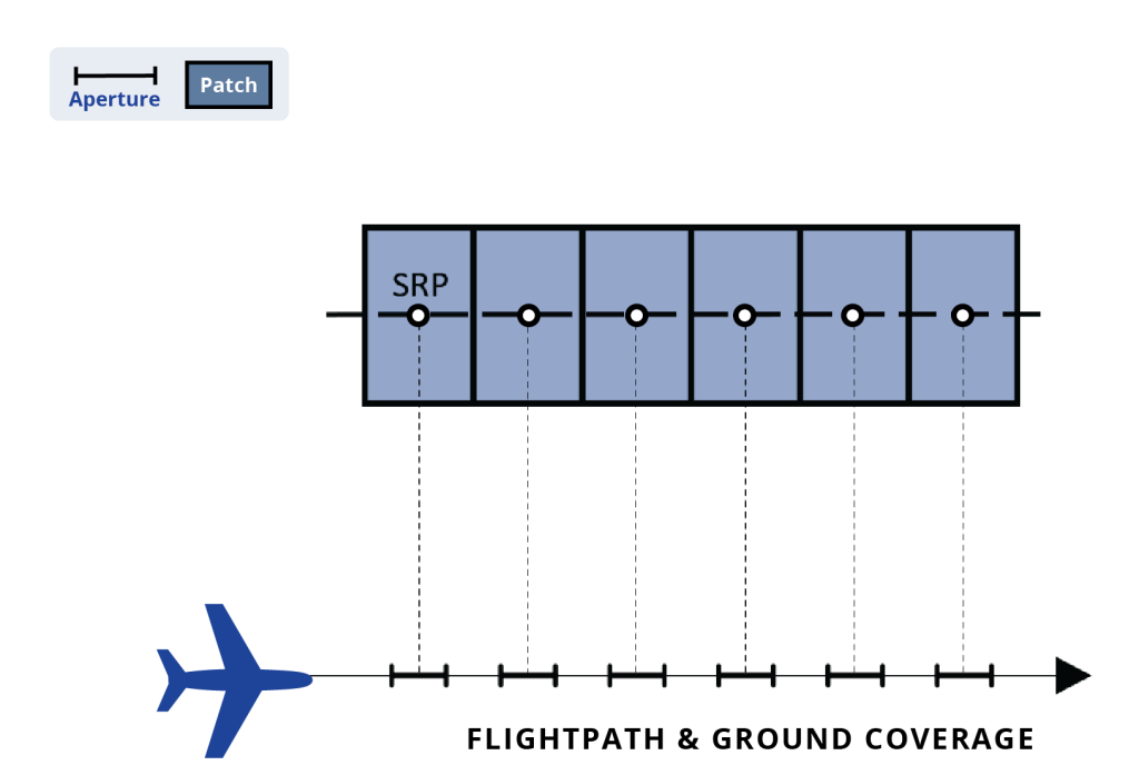
IMAGE SIZE
Primarily a function of resolution. Image size may vary from patch to patch.
RESOLUTION
Available in all resolutions. Finer resolution leads to smaller area coverage on the ground. If resolution is too fine, it may not give contiguous patches. Resolution may not vary during a pass. Minimum resolution for this mode may be larger than for the system.
IMAGE FORMATION
Continues until operator specified linear extent of the terrain has been covered, out of range (small deviations from absolute linear flightpath are generally allowed), or stopped by operator. Depends on system implementation.
VARIANTS
| AUTOPASS Assumes aircraft will continue to fly the same heading as when the command was received. Radar will continue to form images for as long as the SRP is in the FOR or operator stops collection. |
| GUIDED (PLANNED) Aircraft is guided to achieve required flightpath. Typically used when executing a coherent change detection pass or when performing a data collection in which a predefined aircraft/SRP geometry is required. |
RELATED TO
- Class of mosaic modes that build up mosaicked image patches from multiple SRPs.

USE
Image a linear section of terrain that does not fit within a single patch size and is any orientation relative to the plane’s flightpath.

FLIGHTPATH
Arbitrary

FIELD OF REGARD (FOR)
Butterfly wings (dependent on resolution)
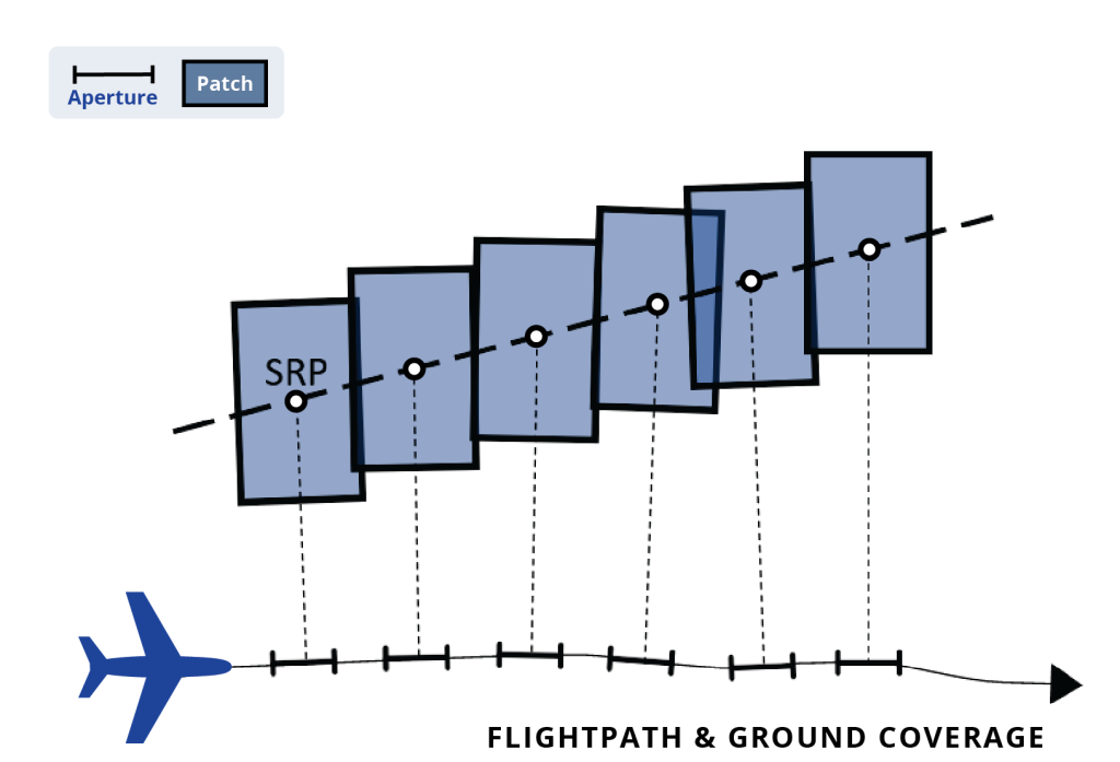
IMAGE SIZE
Primarily a function of resolution. Image size and orientation may vary from patch to patch.
RESOLUTION
Available in all resolutions. Finer resolution leads to smaller area coverage on the ground.
IMAGE FORMATION
Continues until operator specified linear extent of the terrain has been covered, out of FOR, or stopped by operator. Depends on system implementation. SRPs are calculated in real time.
CONSTRAINTS
Arbitrary flightpath but extremely sharp turns can cause the mode to end prematurely. Assumes terrain height does not change. Variable squint angle is allowed.
RELATED TO
- Class of mosaic modes that build up mosaicked image patches from multiple SRPs.
- Like Terrain Following Stripmap (TFSM) except TFSM allows SRP height to change for each patch.

USE
Image along a road or path that does not fit within a single patch size. Route has been pre-planned.

FLIGHTPATH
Pre-planned and assumed to be linear.

FIELD OF REGARD (FOR)
Butterfly wings (dependent on resolution)
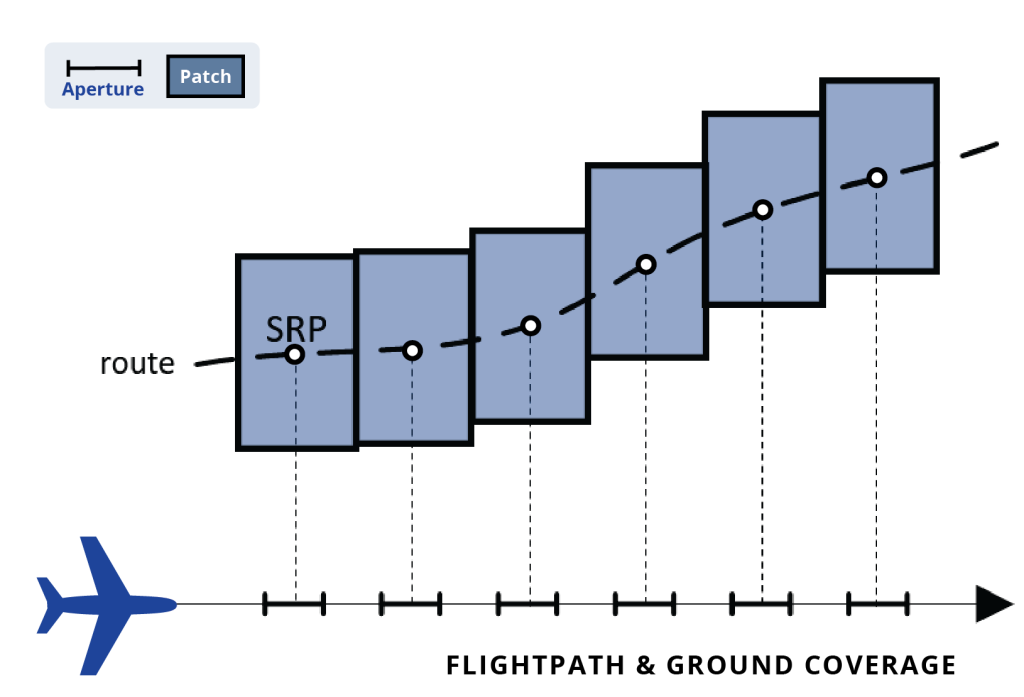
IMAGE SIZE
Mission and flightpath pre-planning are required.
IMAGE SIZE
Selected by pre-planning software. Image size may vary from patch to patch.
RESOLUTION
Selected by pre-planning software. Resolution is selected so that patches are contiguous. Does not vary during the pass. Minimum resolution for this mode may be larger than for the system.
IMAGE FORMATION
Continues until all planned SRP patches have been collected, are out of range, or is stopped by operator.
CONSTRAINTS
Must follow pre-planned flightpath and pre-calculated SRPs. Each SRP must be within radar FOR when the associated patch is imaged.
RELATED TO
- Class of mosaic modes that build up mosaicked image patches from multiple SRPs.
- Subset of Spot modes in which the radar is given a pre-calculated list of SRPs.
Moving Target Indicator
Moving Target Indication (MTI) radar is fundamental for detecting and tracking dynamic objects against stationary backgrounds. Sandia’s leadership in MTI research has led to significant advancements in situational awareness, particularly in challenging clutter environments, delivering critical capabilities for national security.
This mode detects moving objects by analyzing the Doppler shift of their backscattered energy relative to static clutter. Sandia’s innovations in GMTI focus on enhancing detection ranges and improving target discrimination in cluttered landscapes, resulting in advanced airborne GMTI systems that significantly enhance battlefield situational awareness by reliably tracking ground vehicles in diverse and challenging terrain.
Detecting slow-moving targets whose Doppler signatures are embedded within strong clutter echoes requires sophisticated signal processing. Sandia has successfully applied its multi-channel system engineering and signal processing expertise to effectively suppress clutter and extract subtle target movements. Our work in this area ensures reliable detection of targets that would otherwise be obscured, achieving unprecedented detection rates for dismounted personnel and very slow-moving vehicles operating in heavily vegetated or urban environments.
Beyond simple detection, HRR provides detailed structural information about moving targets. By achieving finer range resolution, HRR generates a Radar Cross Section (RCS) profile of a target, often spanning multiple pixels in a Range-Doppler map. Sandia’s advancements in HRR enable enhanced target classification and identification, moving beyond basic detection to sophisticated target characterization, and allowing for the classification of ground vehicles by type based on their unique scattering characteristics.
A specialized subset of GMTI, DMTI focuses on detecting and tracking pedestrian human movement. Sandia’s ongoing research addresses the inherent challenges of DMTI, such as low radar cross-section and complex motion patterns, resulting in substantially improved detection probabilities and tracking accuracies. This capability is vital for critical security and surveillance applications, with Sandia’s advancements in micro-Doppler signature analysis enabling highly accurate dismount detection and tracking for persistent surveillance and border security.
Maritime / Maritime ISAR
Sandia’s expertise extends to advanced maritime radar systems, addressing the unique challenges of sea environments. Our innovations enable superior detection, tracking, and imaging capabilities essential for naval operations, coastal surveillance, and marine safety.
This classic scanning radar mode relies on the antenna’s real beamwidth for azimuth resolution. Operating effectively in maritime environments requires robust clutter rejection techniques to mitigate the effects of ocean waves. Sandia’s research optimizes Maritime Search Mode performance through advanced signal processing algorithms, significantly extending the detection range and reliability of small vessel detection in high sea states for critical maritime domain awareness missions.
While conventional Synthetic Aperture Radar (SAR) images stationary scenes from a moving platform, ISAR is utilized for imaging moving targets. Sandia has significantly advanced Maritime ISAR capabilities for imaging ships and other moving objects at sea. Our research in motion compensation and image formation algorithms enables high-resolution, detailed imagery of maritime targets, even with unknown or complex target motion, producing high-fidelity ISAR images of naval vessels from long standoff ranges, resolving fine structural details for target recognition and forensic analysis.