8.6. Definition of Interactions
Each contact surface can interact with itself and other contact surfaces subject to the conditions specified in a contact interaction. A contact interaction must specify which surfaces should be considered for interaction and parameters governing the interaction.
Defining contact in complex models can be greatly simplified by using “general” contact, in which a single command is used to indicate possible contact between one contact surface and every other contact surface in the model. This command used with a default interactions block to define parameters for the interaction behavior can define contact for an entire model in only a few lines of input.
It is recommended that default interactions blocks be used as much as possible to keep the definition of individual interactions to a minimum. However, if needed, contact interactions can also be defined individually for specific sets of contact surfaces. These can be used to override parameters set in the default command block or can be used without specifying any default parameters. The latter may be more efficient if there are relatively few surfaces in a model and those surfaces interact with a small number of other surfaces, but for complex models with many potential contact surfaces, individually defining all possible contact interactions can be a tedious, error-prone process.
Contact can also be enforced between a surface and itself. This is known as “self” contact, and is used to prevent a part of a surface from penetrating another part of that surface when it folds in on itself. As a general rule, enforcing self contact is more expensive than enforcing contact between different surfaces.
Contact surfaces can be based either on sets of nodes or faces. Node-based surfaces can only interact with face-based surfaces. Face-based surfaces can interact with node or face based surfaces.
The following sections document the commands used to define contact interactions and the properties of those interactions.
8.6.1. Interaction Defaults Block
BEGIN INTERACTION DEFAULTS GENERAL CONTACT = <string>ON|OFF(OFF) SELF CONTACT = <string>ON|OFF(OFF) SURFACES = <string list>surface_names FRICTION MODEL = <string>friction_model_name(FRICTIONLESS) INTERACTION BEHAVIOR = <string>SLIDING|NO_INTERACTION(SLIDING) CONSTRAINT FORMULATION = <string>NODE_FACE|FACE_FACE AL PENALTY = <real>normalPenalty(1.0) [<real>tangentialPenalty]END [INTERACTION DEFAULTS]
The INTERACTION DEFAULTS command block enables contact enforcement either on all contact surfaces or on a subset of the contact surfaces. It is also used to set default parameters for contact interactions. These defaults can be overridden for specific interactions by defining them in INTERACTION blocks. Note that contact enforcement will not occur in a model unless some combination of the INTERACTION DEFAULTS command block and INTERACTION command blocks (see Section 8.6.2) is used to set up surface interactions.
The values specified by the command lines in the INTERACTION DEFAULTS command block are applied by default to all interaction contact surfaces unless overridden by a specific interaction definition. Note that if a friction model is specified for a specific interaction, but that friction model is relevant only for some of the faces in the surfaces involved in the interaction, the friction model specified in the interaction defaults will be used for the remaining faces. For example, if a tied model is specified for an interaction, only the faces that are initially close will be tied. The remaining faces will be enforced using the default friction model. See Section 8.5.11 for more information.
8.6.1.1. General Contact and Self-Contact
GENERAL CONTACT = <string>ON|OFF(OFF)
SELF CONTACT = <string>ON|OFF(OFF)
Setting GENERAL CONTACT to ON specifies that default values set in the command lines of this INTERACTION DEFAULTS command block apply all surfaces defined in the enclosing CONTACT DEFINITION block or to a subset of those surfaces specified in a CONTACT SURFACE line. The default value is OFF. The GENERAL CONTACT command does not impose self-contact.
To enforce self-contact for all surfaces in the enclosing CONTACT DEFINITION block or for a subset of those surfaces specified in a CONTACT SURFACE line, the following command line must be present:
SELF CONTACT = ON
The default value for SELF CONTACT is OFF.
If general contact or self-contact is enabled, contact enforcement may be disabled for individual surfaces or sets of surfaces by using the INTERACTION BEHAVIOR = NO_INTERACTION line in specific INTERACTION command blocks.
8.6.1.2. Specific Surfaces Identification
SURFACES = <string list>surface_names
This command line identifies the contact surfaces to which the surface interaction values defined in the INTERACTION DEFAULTS command block will apply. The surface_names list can include any surface specified in a CONTACT SURFACE command line, a CONTACT SURFACE command block, or created automatically by a SKIN ALL BLOCKS command line in the enclosing BEGIN CONTACT DEFINITION scope.
In the absence of a SURFACES command line, the interaction defaults will apply to all contact surfaces defined in the enclosing BEGIN CONTACT DEFINITION scope.
8.6.1.3. Friction Model
FRICTION MODEL = <string>friction_model_name(FRICTIONLESS)
The FRICTION MODEL command line specifies how surfaces interact with each other. Several simple friction models can be used for friction_model_name including FRICTIONLESS, TIED, and GLUED. Alternatively friction_model_name can be the name of a more complex friction model defined elsewhere in the CONTACT DEFINITION command block. See Section 8.5 for a listing of the available friction models.
The following set of commands will apply the Coulomb friction model fric1 to all surface interactions.
BEGIN CONSTANT FRICTION MODEL fric1
  FRICTION COEFFICIENT = 0.2
END

BEGIN INTERACTION DEFAULTS
  SELF CONTACT = ON
  GENERAL CONTACT = ON
  FRICTION MODEL = fric1
END
If the FRICTION MODEL command is not present, the default interface model is frictionless contact.
8.6.1.4. Interaction Behavior
INTERACTION BEHAVIOR = <string>SLIDING|NO_INTERACTION(SLIDING)
The INTERACTION BEHAVIOR command line specifies whether contact interactions are active. By default, all the interactions specified in the INTERACTION DEFAULTS command block through the GENERAL CONTACT, SELF CONTACT, or CONTACT SURFACE commands are active, that is SLIDING. However, setting INTERACTION BEHAVIOR to NO_INTERACTION will deactivate contact for all these surfaces. In either case, the value for INTERACTION BEHAVIOR set in the INTERACTION DEFAULTS block can be overwritten with the use of the same command line in individual INTERACTION command blocks.
8.6.1.5. Constraint Formulation
CONSTRAINT FORMULATION = NODE_FACE|FACE_FACE
The CONSTRAINT FORMULATION command specifies either node/face or face/face enforcement for contact Face/face contact is used by default except when one of the surfaces is explicitly defined by a node set. In that case, Dash will automatically use node/face in which the :side B” surface will be the one defined by a set of nodes and the :side A” surface will be the contact surface defined by faces. See Section 8.3 for defining contact surfaces by nodes or faces.
See Section 8.6.4 for more information on the difference between node/face and face/face constraints.
![]()
8.6.1.6. Augmented Lagrange Penalty
AL PENALTY = <real>normalPenalty(1.0) [<real>tangentialPenalty]
The AL PENALTY command is used to scale the penalty stiffness that is internally set based on the nodal stiffness of the parts in contact. Both normal and tangential penalty scale factors default to \(1.0\).If only one value is specified, it will be used for both the normal and tangential penalty scale factors. When both normalPenalty and tangentialPenalty are entered, the normal penalty scale factor is set to normalPenalty, and the tangential penalty scale factor is set to tangentialPenalty.
By default, the AL penalty is scaled adaptively as the problem progresses (Section 4.5.1.5). For most problems, the default values of AL PENALTY and LAGRANGE ADAPTIVE PENALTY are robust (all penetration is removed and convergence is achieved). However, for more complicated implicit contact problems, it is sometimes required to modify the AL PENALTY to achieve convergence. However, note that using a small penalty value may result in significant penetration remaining in the model (even though convergence is achieved).
8.6.2. Specific Interactions
BEGIN INTERACTION [<string>name]
   # surface identification
   SURFACES = <string list>surfaces [EXCLUDE <string list>surfaces]
   SIDE A   = <string list>surfaces [EXCLUDE <string list>surfaces]
   SIDE B    = <string list>surfaces [EXCLUDE <string list>surfaces]
   #
   INTERACTION BEHAVIOR = <string>SLIDING|NO_INTERACTION(SLIDING)
   CONSTRAINT FORMULATION = <string>NODE_FACE|FACE_FACE
   FRICTION MODEL = <string>friction_model_name(FRICTIONLESS)
   REMOVE OVERLAP FROM BOTH|SIDE_A|SIDE_B|NONE (BOTH)

   #
   # tolerances
   NORMAL TOLERANCE = <real>norm_tol
   TANGENTIAL TOLERANCE = <real>tang_tol
   OVERLAP NORMAL TOLERANCE = <real>over_norm_tol
   OVERLAP TANGENTIAL TOLERANCE = <real>over_tang_tol

   # interaction specific output
   BEGIN INTERACTION SPECIFIC OUTPUT
     COMPUTE INTERACTION MASK
     COMPUTE INTERACTION FORCE CONTACT
     COMPUTE INTERACTION RELATIVE VELOCITY
     COMPUTE INTERACTION CONTACT STATUS
   END
   CAPTURE TOLERANCE = <real>cap_tol
   #
   # other implicit only commands
   AL PENALTY = <real>normalPenalty(1.0) [<real>tangentialPenalty]
   PUSHBACK FACTOR = <real>pushback_factor(1.0)
   TENSION RELEASE = <real>ten_release(0.0)
   TENSION RELEASE FUNCTION = <string>ten_release_func
   #
END [INTERACTION <string>name]
Values for specific contact interactions can be set using the INTERACTION command block. If an INTERACTION DEFAULTS command block is present within a CONTACT DEFINITION command block, the values provided by an INTERACTION command block override the defined defaults. If an INTERACTION DEFAULTS command block is not present, only those interactions defined by INTERACTION command blocks are searched for contact, and values without system defaults must be specified.
The INTERACTION command block begins with:
BEGIN INTERACTION [<string>name]
and ends with:
END [INTERACTION <string>name]
where name is a name for the interaction. Note that this name is currently used only for informational output purposes and is not required.
The valid commands within an INTERACTION command block are described in Section 8.6.2.1 through Section 8.6.2.2.
8.6.2.1. Surface Identification
# preferred for explicit and implicit face/face contact
SURFACES = <string list>surfaces [EXCLUDE <string list>surfaces]
#
# preferred for implicit node/face enforcement
SIDE A   = <string list>surfaces [EXCLUDE <string list>surfaces]
SIDE B   = <string list>surfaces [EXCLUDE <string list>surfaces]
There are two methods to identify the surfaces described by a specific interaction. One method is to identify all surfaces in a single line with the SURFACES command line. The surface list must contain at least two surfaces. This command will define a contact interaction between each surface on the command line and every other surface listed. To specify self contact, the surface must appear in the SURFACES command line twice. For any pair of surfaces listed on the SURFACES command line, the determination of which surface is SIDE A and which surface is SIDE B is made using a set of rules based largely on the characteristic face size for that contact surface. The characteristic face size for each contact surface is listed in the log file. The face with the smallest characteristic face size is generally selected as the SIDE B for that particular interaction.
The second method is to use the SIDE A and SIDE B command lines directly. In Sierra/SM, contact surfaces must be identified using the SIDE A and SIDE B command lines for kinematic enforcement. For augmented Lagrange enforcement (default), either method of identifying the surfaces may be used. Each of these command lines takes as input a list of names of contact surfaces defined in the CONTACT DEFINITION block. This interaction will be defined between each surface in the side A list and each surface in the side B list. Additionally, a surface may not be present in both lists.
The option all_surfaces is a special reserved word equivalent to directly specifying all contact surfaces known by the contact block in a list. Optionally, the EXCLUDE keyword can used along with a list of surface names to exclude from the list.
If the SURFACES, SIDE A, or SIDE B command lines appear multiple times within an INTERACTION block, their surface lists will be concatenated. The effect is equivalent to specifying all the surface names on a single line. The SURFACES command line cannot be used in the same `` INTERACTION`` block as SIDE A and SIDE B commands.
The following examples demonstrate ways to identify contact surfaces involved in an interaction:
This command defines an interaction between s1 and s2:
SURFACES = s1 s2
This defines a self contact interaction between s1 and itself:
SURFACES = s1 s1
This defines a set of interactions between s1 and s2, s1 and s3, s2 and s3:
SURFACES = s1 s2 s3
This defines a full set of interactions between s1 and itself, s2 and itself, and between s1 and s2:
SURFACES = s1 s1 s2 s2
This command defines a set of interactions between all pairs of defined surfaces in the model, with the exception of surfaces s7 and s8, which have no interactions:
SURFACES = all_surfaces exclude s7 s8
This command defines a set of interactions between all pairs of defined surfaces in the model, as well interactions between each surface and itself, with the exception of surfaces s7 and s8, which have no interactions:
SURFACES = all_surfaces all_surfaces exclude s7 s8
These commands define an interaction between the nodes of s1 and the faces of m1:
SIDE A = m1
SIDE B = s1
These commands define a set of interactions between the nodes of s1 and the faces of both m1 and m2, and between the nodes of s2 and the faces of both m1, the nodes of s2 and m2.
SIDE A = m1 m2
SIDE B = s1 s2
These commands define that the nodes of surface s1 are searched against all other contact faces in the contact definition block.
SIDE A = all_surfaces exclude s1
SIDE B = s1
8.6.2.2. Interaction Behavior
INTERACTION BEHAVIOR = <string>SLIDING|NO_INTERACTION(SLIDING)
This command sets the search behavior for a specific contact surface pair or for self-contact of a surface. See Section 8.6.1.4 for a discussion of this command line.
Since the default value is SLIDING, this command line is most often used to deactivate enforcement for the specific surfaces listed in this INTERACTION by setting the value to NO_INTERACTION.
8.6.2.3. Constraint Formulation
CONSTRAINT FORMULATION = NODE_FACE|FACE_FACE
The CONSTRAINT FORMULATION command specifies node/face or face/face enforcement for contact constraints for the specific surfaces listed in the INTERACTION block. See Section 8.6.1.5 for a discussion of this command line. See Section 8.6.4 for more information on the difference between node/face and face/face constraints.
8.6.2.4. Friction Model
FRICTION MODEL = <string>fric_model_name(FRICTIONLESS)
You can set the friction model for the interaction for a specific contact surface pair or for self-contact of a surface by using the above command line in an INTERACTION command block. See Section 8.6.1.3 for a discussion of this command line.
8.6.2.5. Interface Material
INTERFACE MATERIAL = <string>int_matl_name
  MODEL = <string>int_model_name
The Tvergaard Hutchinson and Thouless Parmigiani cohesive models (see Section 5.3) can be used as interface models within contact. Interactions between faces are created by a contact search performed in the initial configuration (similar to tied contact), so cohesive zones are only created between faces that are initially contacting. The relative motion of the faces on opposing sides of an interface is governed by the behavior of the cohesive zone model.
Note that these interface models can only be used with Dash contact. Additionally, due to the need to store state variables, these models can only be used with node-face contact interactions. A further restriction is the interactions must be defined between sidesets, to compute the correct area contribution. The side B sideset determines the nodal area of the cohesive interaction.
The interface model always takes one momentum balance iteration since we are not trying to close a gap in an Augmented Lagrangian fashion. Instead, whatever traction/force is computed for the gap, that force is what is applied to the nodes.
Warning
Interface contact models can only be used with node-face contact interactions, and they must be defined between two sidesets.
8.6.2.6. Remove or Ignore Overlap from a Specific Side
REMOVE OVERLAP FROM BOTH|SIDE_A|SIDE_B|NONE (BOTH)
When removing initial overlap, the side the overlap is removed from may be specified with the REMOVE OVERLAP FROM line command. By default, overlap is removed from both sides equally (BOTH). The specific side the overlap is removed from may be specified as either SIDE_A or SIDE_B of the interaction. This is especially useful when removing overlap from surfaces in an interaction who have very different mesh sizes. The NONE option can be specified to ignore overlap removal for a specific interaction, which may be useful if the overlap is intentional as in some preload use-cases.
8.6.2.7. Tolerances
NORMAL TOLERANCE = <real>norm_tol
TANGENTIAL TOLERANCE = <real>tang_tol
OVERLAP NORMAL TOLERANCE = <real>over_norm_tol
OVERLAP TANGENTIAL TOLERANCE = <real>over_tang_tol
CAPTURE TOLERANCE = <real>cap_tol
Tolerances for the interaction of specific contact surfaces or for self-contact of surfaces are set with the above tolerance-related command lines in an INTERACTION command block. See Section 8.9.6.1 on search tolerances and Section 8.9.4 on overlap tolerances for a complete discussion of tolerances for contact.
The contact functionality in Sierra/SM uses a box defined around each face to locate nodes that may potentially contact the face. This box is defined by a tolerance normal to the face and another tolerance tangential to the face (see Fig. 8.25). The code adds the maximum motion over a time step to these tolerances when identifying interactions. In the above command lines, the parameter norm_tol is the normal tolerance (defined on the NORMAL TOLERANCE command line) for the search box and the parameter tang_tol is the tangential tolerance (defined on the TANGENTIAL TOLERANCE command line) for the search box.
In most cases, the normal and tangential tolerances computed internally are optimal values, and manual setting of tolerances should be avoided. If specific normal and tangential tolerances are set, the tolerances used should not exceed roughly half of the minimum characteristic face size. Tolerances beyond that length may cause instability in the contact solution.
![]() The
The CAPTURE TOLERANCE, which should be no larger than the NORMAL TOLERANCE, is used to determine which side B nodes near a side A surface should be pulled to the side A surface and considered for contact. (This applies to side B nodes which have not penetrated the side A surface. Side B nodes that have penetrated the side A surface will be pushed to the surface regardless of the CAPTURE TOLERANCE.) If later checks determine that a side B node that was pulled to the surface (because it was nearer the surface than the CAPTURE TOLERANCE value) is in fact in tension and should be released, that side B node will not be considered as a potential contact node again during the load step as long as the node remains within the NORMAL TOLERANCE.
Warning
If CAPTURE TOLERANCE is set with anything other than KINEMATIC enforcement it will be ignored.
8.6.2.8. Interaction Specific Output
BEGIN INTERACTION SPECIFIC OUTPUT
  COMPUTE INTERACTION MASK
  COMPUTE INTERACTION FORCE CONTACT
  COMPUTE INTERACTION RELATIVE VELOCITY
  COMPUTE INTERACTION CONTACT STATUS
END
INTERACTION SPECIFIC OUTPUT allows a user to output special quantities of interest for a contact interaction pair. The interaction output is generated with respect to each Side A vs Side B node-face or face-face pair.
The COMPUTE INTERACTION MASK command creates a nodal variable named <interaction_name>_interaction. This variable shows which nodes are a part of the interaction defined. A value of 0 means the node is not in the interaction, a value of 1 means the node is a part of the SIDE A surface and a value of 2 means the node is a part of the SIDE B surface.
The COMPUTE INTERACTION FORCE CONTACT command creates a nodal variable named <interaction_name>_force_contact. This variable shows the contact force at the nodes that was generated for this interaction.
The COMPUTE INTERACTION RELATIVE VELOCITY command creates a number of output variables related to the relative velocity at the contact interaction. A global variable named <interaction_name>_normal_relative_velocity is the max relative velocity in the normal direction of impact over time. A nodal variable named <interaction_name>_relative_velocity is the relative velocity of each node-face or face-face pair, interpolated to the nodes of each face using the shape functions of the interaction. A nodal variable named <interaction_name>_max_normal_relative_velocity is the max relative velocity in the normal direction that a node sees during a timestep. For example, if a face on the SIDE A side contacts multiple faces on the SIDE B side, the max value of those face interactions is saved to the nodes.
The COMPUTE INTERACTION CONTACT STATUS command creates a nodal variable named <interaction_name>_contact_status. A value of 0 means the node is not in contact with another face in the interaction. A value of 1 means the node is currently in contact with another face in the interaction.
A summary of all of the output variables is explained in Table 8.1 below.
Interaction Output |
Variable Type |
Variable Name |
|---|---|---|
|
|
|
|
|
|
|
|
|
|
|
|
|
|
|
|
|
|
![]()
8.6.2.9. Augmented Lagrange Penalty
AL PENALTY = <real>normalPenalty(1.0) [<real>tangentialPenalty]
See Section 8.6.1.6 for a discussion of this command line.
![]()
8.6.2.10. Pushback Factor
PUSHBACK FACTOR = <real>pushback_factor
Implicit contact feature.
The command line PUSHBACK FACTOR can be used to set the fraction of the gap to be removed in a contact model problem. The default value is 1.0 which removes the entire gap in one contact model problem. Setting the pushback factor to 0.25 will result in the gap being removed in 4 contact model problems.
![]()
8.6.2.11. Tension Release
TENSION RELEASE = <real>ten_release(0.0)
The command line TENSION RELEASE can be used to set a traction threshold. Below the threshold, side B nodes (that are in contact with side A faces) will not be released.
When this value is set and a side B node is in tension, it will only be allowed to pull away from the side A surface if the side B node’s traction is greater than the TENSION RELEASE tolerance. The default value for TENSION RELEASE is 0.0.
![]()
8.6.2.12. Tension Release Function
TENSION RELEASE FUNCTION = <real>ten_release_func
The command line TENSION RELEASE FUNCTION provides a way for the tension release threshold to be set using a function from the input file. If the TENSION RELEASE line command is also present, the threshold used by the code will be the TENSION RELEASE value multiplied by the value obtained from the function.
8.6.3. Interaction Behavior for Particle Element Blocks
Element blocks containing particle elements (SPH, Mass Particle, or point masses) undergo special treatment, as described below.
Because the SPH element algorithms already define contact like interactions elements, it is typically not desirable to enforce self-contact within those element blocks, so self-contact is disabled by default for these blocks. For the same reason, contact between blocks of SPH elements is disabled by default.
Mass particles define both self-contact and inter-block interactions by default. Point masses behave similar to mass particles, but the ‘skin’ of a point mass block is just the nodes of the block. The ‘skin’ of a mass particle block is lofted spheres. Node/face contact for other particle types can be used by defining contact on the particle node sets, using the ‘contact nodeset’ command, or specifying the constraint formulation to NODE_FACE.
Elements converted to particles are placed in a new element block. The name of the new element block is the name of the parent block with _particles appended. For example, particles created from block_1 are placed in a new element block named block_1_particles. The SKIN ALL BLOCKS command creates a new contact surface containing the particles with the same name as the particle block (block_1_particles in this example).
By default, the contact surface for the particles inherits interaction definitions from the parent block, subject to the exceptions listed above for interactions between particles blocks. However, interactions specifying a friction model as TIED or DYNAMIC_TIED will be converted to FRICTIONLESS by default to prevent spurious constraints from being created. Spurious constraints are created when using the TIED or DYNAMIC_TIED friction models because the reference configurations between converted particles and solid elements are incompatible. If possible, the GLUED friction model is advised as a surrogate for the TIED friction model for interactions involving particles.
Any of the above defaults can be overridden by defining individual interactions. For example, if block_1 and block_2 are SPH particle blocks, they will not interact though contact by default. However, the following command block can be included to cause contact to be enforced between them.
BEGIN INTERACTION
  SURFACES = block_1 block_2
END
If a single contact surface is defined by combining multiple types of objects, the special particle-specific default behavior described in this section is disabled. For example, the following command block will turn on self-contact for all entities within the surface s1, including between the particles in block_2_particles.
BEGIN INTERACTION DEFAULTS
  SELF CONTACT = ON
END
CONTACT SURFACE s1 CONTAINS block_1 block_2_particles surface_3
8.6.4. Face/Face vs. Node/Face Constraints
Interactions can be formulated as either face/face constraints or node/face constraints. Face/face is the default for all surface on surface interactions. Node/face is the default of node set on surface interactions or certain types of particle on surface interactions. The constraint formulation type can be set in the INTERACTION or INTERACTION DEFAULTS command blocks. The two types of constraints have trade-offs in terms of robustness and accuracy discussed in this section.
A node/face constraint is a constraint between a single node and a single face. In a node/face constraint a node is not allowed to move through a face. The node is tied to a specific spot on the face, allowed to slide along the face, or allowed to move away from the face depending on the friction model used. An example of node for surface nodes (red) sliding off of a block (blue) is shown in Fig. 8.16. In the figure the constraints themselves are indicated with green arrows.
Node/face constraints have some limitations. In order to correctly resolve nodes sliding around corners of curved surfaces node/face constraints generally require use of some tangential tolerance (shown in dashed line). Note that with node face/face constraints the red nodes of the constraints may not penetrate the blue faces. The blue nodes however, may penetrate the red faces. Node/face constraints can potentially be setup symmetrically so that both sides of the interactions contain both the nodes and the faces of constraints. However, this symmetric setup leads to chaining of constraints that may be difficult to resolve particularly in implicit analyses.
A face/face constraint is a constraint between two faces. The face/face constraint constrains the overlapping area of the two faces. In a face/face constraint no part of either face is allowed to move through any part of the other face. Faces remain tied together, can slide against one another, or move apart depending on the friction model used. An example of a surface (red) sliding off of a block (blue) with face/face constraints is shown in Fig. 8.17. In the figure the constraints are represented with green regions of overlap between faces.
Face/face constraints do not require any tangential tolerances, though do have some limitations. Face/face constraints are most accurate when the two constrained faces are parallel. Face/face constraints can misalign faces, though sometimes with accuracy limitations particularly for frictional quantities.
When tying together meshes with node/face constraints the forces are applied to discrete points potentially resulting in artificial stress concentrations. When tying with face/face constraints the contact forces are instead applied via tractions on the constrained faces. Thus face/face constraints generally results in a smoother tied solution with less severe artificial stress concentrations.
For node/face constraints the friction law is evaluated and the forces applied directly at the side B nodes of the constraints. This has the advantage that frictional output quantities can be accumulated easily over time at the nodal points. For face/face constraints the exact location of the constraint moves in time. This can smear the history of frictional quantities making them less distinct and less accurate.
In some cases, face/face constraints are more robust than node/face constraints and can more accurately solve certain classes of problems. Face/face constraints often work better than node/face for problems with high loading rates and stiffening materials. Node/face contact enforcement tends to aggravate hourglass modes when used on these types of problems. Additionally, problems with many blocks meeting at corners may often run more robustly with face/face constraints. In node/face constraints a node will only interact with one other face at a time making corner contacts inherently ambiguous. For face/face constraints the ambiguity is removed by moving the constraints to faces where the interaction is unambiguous even for complex geometry.
Node/Face constraints are generally a bit faster to evaluate than face/face constraints, though the performance difference is usually negligible in most production sized analyses.
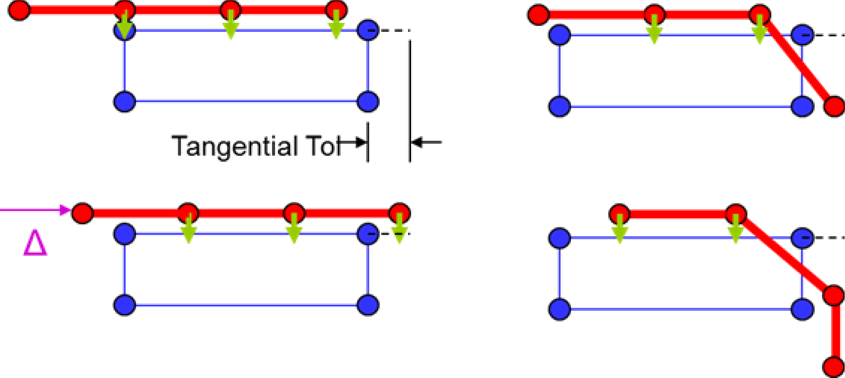
Fig. 8.16 Node/face constraint example.
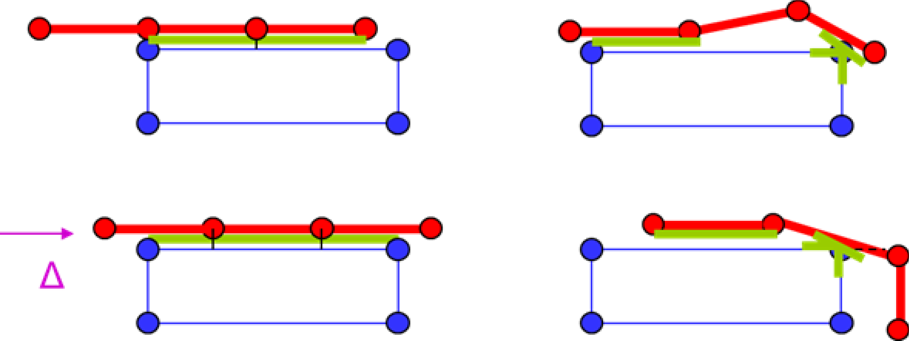
Fig. 8.17 Face/face constraint example.