7.7. Force Boundary Conditions
A variety of force boundary conditions are available in Sierra/SM. This section describes these boundary conditions.
7.7.1. Pressure
BEGIN PRESSURE
  #
  # surface set commands
  SURFACE|SIDESET|SIDE SET = <string list>surface_names
  REMOVE SURFACE = <string list>surface_names
  BLOCK = <string list> block_names
  ASSEMBLY = <string list> assembly_names
  INCLUDE ALL BLOCKS
  #
  # specification commands
  FUNCTION = <string>function_name
  VELOCITY DAMPING COEFFICIENT = <real>damping_coefficient
  # user subroutine commands
  SURFACE SUBROUTINE = <string>subroutine_name |
    NODE SET SUBROUTINE = <string>subroutine_name
  SUBROUTINE DEBUGGING OFF | SUBROUTINE DEBUGGING ON
  SUBROUTINE REAL PARAMETER: <string>param_name
    = <real>param_value
  SUBROUTINE INTEGER PARAMETER: <string>param_name
    = <integer>param_value
  SUBROUTINE STRING PARAMETER: <string>param_name
    = <string>param_value
  #
  # external pressure sources
  READ VARIABLE = <string>var_name
  COPY VARIABLE = <string>var_name [FROM MODEL <string>model_name]
    MAP_BY_PROXIMITY|MAP_BY_ID(MAP_BY_PROXIMITY)
  COPY NEAREST ELEMENT|FACE|NODE <string>varName
    FROM MODEL <string>model_name
  TIME = <real>time|FIRST|LAST
  OBJECT TYPE = <string>NODE|FACE(FACE)

  FIELD VARIABLE = <string>field_variable
  SCALAR SOURCE VARIABLE = <string>var_name INDEX
    <integer>var_index REGION <string>region_name
  #
  # pressure masking
  MASKING METHOD = OFF|ON|CONTACT(OFF)
  ADDITIONAL MASKING FIELD = <string>var_name
  #
  # output external forces from pressure
  EXTERNAL FORCE CONTRIBUTION OUTPUT NAME =
    <string>variable_name
  #
  # additional commands
  SCALE FACTOR = <real>scale_factor(1.0)
  ACTIVE PERIODS = <string list>period_names
  INACTIVE PERIODS = <string list>period_names

  INTEGRATION METHOD =
    CODE SELECTED|MULTILINEAR|QUADRATIC(CODE_SELECTED)

END [PRESSURE]
The PRESSURE command block applies a pressure to each face of the associated surfaces. The pressure field can be constant over the faces and vary in time, dependent on the average face velocity based on a damping coefficient, or determined by a user subroutine. If the pressure field is constant over the faces and has only a time-varying component, the function command in the above command block can be used to specify the pressure field. For a velocity-dependent pressure, a damping coefficient is specified. If the pressure field has both time-varying and spatially varying components, user subroutine commands are used to specify the pressure field. The pressure field may also be obtained from a mesh file or from another SIERRA code through a transfer operator. Only one of these options – function, velocity damping coefficient, user subroutine, mesh file, transfer from another code – may be used to specify the pressure field in a particular PRESSURE command block.
The PRESSURE command block can be used for surfaces that have faces derived from solid elements (eight-node hexahedra, four-node tetrahedra, eight-node tetrahedra, etc.), membranes, and shells. The PRESSURE command block can also be used for particle like elements if the elements are created through the use of element death particle conversion, Section 6.5.6.9. The surfaces must be defined on the original solid elements.
Pressure is integrated in the current deformed model configuration. Thus if due to displacement a face grows, shrinks, or rotates the net force produced by the pressure boundary condition will change.
A pressure boundary condition generates nodal forces that are summed into the external force vector that is used to calculate the motion of a body. The external force vector contains the contribution from all forces acting on the body. There is an option in the PRESSURE command block to save information about the contribution to the external force vector due only to pressure loads. This option does not change the magnitude or time history of the pressure load (regardless of how they are defined), but merely stores information in a user-accessible variable.
Warning
Pressure is integrated over each face and applied at the nodes with forces. The contribution to each node on a face is based on topology, which in some cases is simplified from that of the underlying element. For quadrilateral, triangular, and a few higher order faces (e.g., eight and nine node quadrilaterals) the topology used is exact, but in some cases it is an approximation formed from subdividing the face into multiple triangular faces.
The PRESSURE command block contains five groups of commands—surface set, function, user subroutine, external pressure, and output external forces. Each of these command groups is basically independent of the others. In addition to the command lines in the five command groups, there are two additional command lines: SCALE FACTOR and ACTIVE PERIODS. The SCALE FACTOR command line will apply an additional scaling factor to the pressure value computed. The ACTIVE PERIODS and INACTIVE PERIODS command lines are used to activate or deactivate this force boundary condition for certain time periods. Following are descriptions of the different command groups.
7.7.1.1. Surface Set Commands
The surface set commands portion of the PRESSURE command block defines a set of surfaces associated with the pressure field and can include some combination of the following command lines:
SURFACE = <string list>surface_names
BLOCK =  <string list>block_names
ASSEMBLY =  <string list>assembly_names
INCLUDE ALL BLOCKS
REMOVE SURFACE = <string list>surface_names
In the SURFACE command line, a series of surfaces may be given through the string list surface_names. When using the BLOCK command the pressure will be applied to the exterior boundary of the block. In the ASSEMBLY command line, the pressure will be applied to the exterior boundary of the blocks in an assembly, or to the surfaces in an assembly. When using the INCLUDE ALL BLOCKS command the pressure will be applied to the exterior boundary of all blocks in the model. Note, the NODE SET|NODESET command is not valid for specifying an entity for pressure boundary conditions.
There must be at least one SURFACE, BLOCK, ASSEMBLY, or INCLUDE ALL BLOCKS command line in the command block. The REMOVE SURFACE command allows creation of an application surface formed from the union of surfaces specified in the SURFACE, BLOCK, ASSEMBLY, or INCLUDE ALL BLOCKS minus those surfaces specified in the REMOVE SURFACE command. Assemblies may contain blocks, surfaces, or assemblies of these.
See Section 7.1.1 for more information about the use of these command lines for creating a set of surfaces used by the boundary condition.
7.7.1.2. Specification Commands
If a simple time-dependent function is used (e.g. piecewise-linear, constant), the pressure vector at any given time is the same for all surfaces associated with the particular PRESSURE command block. Alternatively, spatially-varying pressure fields may be achieved through the use of more complex analytic functions. The direction of the pressure vector is constant for all time; the magnitude of the pressure vector may vary with time.
Following is the command line used to specify the pressure with a function:
FUNCTION = <string>function_name
The pressure is applied in the opposite direction to the outward normals of the faces that define the surfaces. The magnitude of the pressure is specified by the FUNCTION command line. This references a function_name (defined in the SIERRA scope in a FUNCTION command block) that specifies the magnitude of the pressure vector as a function of time. The magnitude can be scaled by use of the SCALE FACTOR command line described in Section 7.7.1.7.
A face force based on a velocity damping coefficient can be applied using the command line:
VELOCITY DAMPING COEFFICIENT = <real>damping_coefficient
In this case, nodal forces will be applied to the nodes of any faces included in the surfaces associated with the PRESSURE command block. A force vector acting normal to the face is computed by multiplying the average nodal velocity normal to the face by the damping coefficient. This face force is then evenly distributed among the nodes of the face.
7.7.1.3. User Subroutine Commands
If the user subroutine option is used, the pressure may vary spatially at any given time for each of the surfaces associated with the particular PRESSURE command block. The user subroutine option allows for a more complex description of the pressure field than does the function command, but also requires writing a user subroutine to implement this capability. The user subroutine will be used to define a pressure for every face to which the boundary condition will be applied. The subroutine will be called by Sierra/SM at the appropriate time to generate the pressure field.
Following are the command lines related to the user subroutine option:
SURFACE SUBROUTINE = <string>subroutine_name |
  NODE SET SUBROUTINE = <string>subroutine_name
SUBROUTINE DEBUGGING OFF | SUBROUTINE DEBUGGING ON
SUBROUTINE REAL PARAMETER: <string>param_name
  = <real>param_value
SUBROUTINE INTEGER PARAMETER: <string>param_name
  = <integer>param_value
SUBROUTINE STRING PARAMETER: <string>param_name
  = <string>param_value
The user subroutine option is invoked by using the SURFACE SUBROUTINE command line or the NODE SET SUBROUTINE command line. The string subroutine_name in both command lines is the name of a FORTRAN subroutine that is written by the user. The particular command line selected depends on the mesh-entity type for which the pressure field is being calculated. Associating pressure values with faces would require the use of a SURFACE SUBROUTINE command line. Associating pressure values with nodes would require the use of a NODE SET SUBROUTINE command line.
Following the selected subroutine command line are other command lines that may be used to implement the user subroutine option. These command lines are described in Section 10.2.2.2 and consist of SUBROUTINE DEBUGGING OFF, SUBROUTINE DEBUGGING ON, SUBROUTINE REAL PARAMETER, SUBROUTINE INTEGER PARAMETER, and SUBROUTINE STRING PARAMETER. Examples of using these command lines are provided throughout Section 10.2.
The magnitude set in the user subroutine can be scaled by use of the SCALE FACTOR command line, as described in Section 7.7.1.7.
Usage requirements. Following are the usage requirements for the two types of subroutines:
The surface subroutine operates on a group of faces. The subroutine will return one output value per face. Suppose a provided user subroutine returns the pressure information through an array
output_value. The valueoutput_value(1,iface)corresponds to the average pressure on faceiface. The values of the flags array are not used.The node set subroutine provided will return one value per node. Suppose a provided user subroutine returns the pressure information through an array
output_value. The return valueoutput_value(1,inode)is the pressure at the nodeinode. The total pressure on the each face is found by integrating the pressures at the nodes. The values of the flags array are not used.
See Section 10.2 for more details on implementing the user subroutine option.
7.7.1.4. External Pressure Sources
Pressure may be obtained from two different external sources. The first option for obtaining pressure uses a mesh database. The pressures are read from a finite element model defined via the FINITE ELEMENT MODEL command block described in Section 6.1. The finite element model can either be the model used by the region for its mesh definition as specified with the USE FINITE ELEMENT MODEL command (see Section 2.3), or it can be a different (but compatible) model. The following command lines control the use of an external mesh database to prescribe the pressure:
READ VARIABLE = <string>var_name
COPY VARIABLE = <string>var_name [FROM MODEL <string>model_name]
  MAP_BY_PROXIMITY|MAP_BY_ID(MAP_BY_PROXIMITY)
COPY NEAREST ELEMENT|FACE|NODE <string>varName
  FROM MODEL <string>model_name
TIME = <real>time|FIRST|LAST
OBJECT TYPE = <string>NODE|FACE(FACE)
See Section 7.3.5 for more details.
The OBJECT TYPE command line specifies whether the pressure field on the mesh file is specified for nodes (the mesh object type is NODE) or for faces (the mesh object type is FACE). If the OBJECT TYPE command line is not present, it is assumed that the named variable is defined on faces.
If the pressure field is defined on the nodes, the field used should have one value per node which is the node centered pressure. If the pressure field is defined on faces, there are two options for field format. The first option is to have one value defined per face, which defines a constant pressure over each face. The second option is to define \(numNode\) values per face where \(numNode\) is the number of nodes on each face (four per quad, three per triangle, etc.) When this option is used, the pressure field is defined at each corner of the face; this linearly varying pressure is then integrated over the face to compute the net forces. These nodal pressure weightings are sometimes called pressure distribution factors in other codes.
Distribution factors can be applied through pressure by using read variable. When using READ VARIABLE = DISTRIBUTION_FACTORS the distribution factors set on the mesh will be read in and treated like an additional scale factor. For example. If you have a FUNCTION, SCALE FACTOR, and DISTRIBUTION_FACTORS in the same pressure block the force applied will be ‘FUNCTION * SCALE FACTOR * DISTRIBUTION_FACTORS * nodal area’.
The second option for obtaining pressure from an external source relies on the transfer of information from another SIERRA code. The command for obtaining pressure information by transfer from another code is:
FIELD VARIABLE = <string>var_name
Here, var_name is the name of the variable where pressure information is to be stored. The pressure information will be transferred into this variable from another SIERRA code via a transfer operator.
The third option for obtaining pressure from an external source relies on the exchanging of information in a two-way coupled simulation with another SIERRA code. The command for obtaining pressure in this manner is:
SCALAR SOURCE VARIABLE = <string>var_name INDEX
      <integer>var_index REGION <string>region_name
In this command, var_name is the name of the variable where pressure information is stored in the other code. INDEX var_index is the index into the variable for multi-component fields. If the pressure source is a single global, the command is INDEX 0. REGION region_name is the name of the Sierra region Sierra/SM is coupling to.
An example of using this command would be the following: In the Sierra code Aria, a bulk fluid node can be used to calculate the temperature and pressure of air in an enclosed volume. Once this is calculated, the bulk fluid node pressure can then be applied to the interior surface of the container enclosing the air in the Adagio region. Similarly, this command can also be used in thermal-mechanical foam decomposition simulations.
7.7.1.5. Masking
Masking will remove the external force contribution of pressure on some of the nodes included in the pressure boundary condition. This capability can be used to avoid duplicity in boundary conditions, for example by masking the nodes with non-zero contact forces. The masking command options are:
MASKING METHOD = OFF|ON|CONTACT(OFF)
ADDITIONAL MASKING FIELD = <string>var_name
The MASKING METHOD defines whether masking is active for the pressure boundary condition and how it should be applied. The default behavior (OFF) is to not mask. The ON masking method will apply masking by evaluating a user-specified nodal field. The ADDITIONAL MASKING FIELD defines this masking field, which can be any scalar or vector nodal field stored on the nodes included in the pressure boundary condition. The external force contribution of the pressure will be zero for every node where the magnitude of the masking field is non-zero. The CONTACT masking method will automatically mask pressure on nodes with non-zero contact forces. The CONTACT masking method will mask pressure on any nodes with non-zero contact and any nodes with a non-zero user-specified field if the ADDITIONAL MASKING FIELD is specified.
7.7.1.6. Output Command
This command line lets the user create a variable that stores information about the contribution to the external force vector at a node arising solely from a pressure:
EXTERNAL FORCE CONTRIBUTION OUTPUT NAME =
  <string>variable_name
If the above command line appears in a PRESSURE command block, then there will be a variable created with whatever name the user specifies for variable_name. The variable defines a three-dimensional vector at each node associated with this particular command block. The three-dimensional vector at each node represents the external force due solely to the pressure on the elements attached to that node. For example, if one of the nodes associated with this particular command block has four elements attached to it and each element has a pressure load, then the external force contribution at the node would be summed from the pressure load for all four elements.
Once this variable for the external force contribution from a pressure load is specified, it may be used like any other nodal variable. The user can, for example, specify the variable as a nodal variable to be output in a RESULTS OUTPUT command block. Or the user can reference the variable in a user subroutine.
7.7.1.7. Additional Commands
These command lines in the PRESSURE command block provide additional options for the boundary condition:
SCALE FACTOR = <real>scale_factor(1.0)
ACTIVE PERIODS = <string list>period_names
INACTIVE PERIODS = <string list>period_names
The SCALE FACTOR command line is used to apply an additional scaling factor, which is constant in both time and space, to all vector magnitude values of the field defined by the function command or the user subroutine. For example, if the magnitude of the pressure in a time history function is given as 1.5 from time 1.0 to time 2.0 and the scale factor is 0.5, then the magnitude of the pressure from time 1.0 to 2.0 is 0.75. The default value for the scale factor is 1.0.
Generally if multiple pressure sources are defined they are multiplied together. For example if all the FUNCTION, SCALE FACTOR, and READ VARIABLE commands were defined the total pressure at each face would be the value of the function at the current time, times the value of the mesh variable at the specific faces, times the scaling factor. However, Some combinations of sources conflict and are not allowed to be used in the same boundary condition such as SUBROUTINE and READ VARIABLE.
The ACTIVE PERIODS and INACTIVE PERIODS command lines determine when the boundary condition is active. See Section 2.6 for more information about these command lines.
7.7.1.8. Surface Integration Schemes
INTEGRATION METHOD =
  CODE SELECTED|MULTILINEAR|QUADRATIC(CODE_SELECTED)
By default Sierra/SM will pick the pressure integration method that is most consistent with the underlying element type. For example using a quadratic pressure integration scheme on the face of a twenty seven node hexahedron and a linear pressure integration scheme on the face of eight node hexahedron. The higher order tetrahedra elements present some special cases. Fully integrated ten node tetrahedra are more consistent with a quadratic surface integration scheme and by default will use a quadratic pressure integration. The composite or mean quadrature ten node tetrahedra are more consistent with a multi-linear surface integration scheme and by default will use the linear integration method. An optional command INTEGRATION METHOD can be used to override this default behavior and explicitly set the integration scheme for pressure on six node triangle faces.
7.7.1.9. Example
BEGIN FUNCTION One
  TYPE = CONSTANT
  BEGIN VALUES
    1.0
  END VALUES
END FUNCTION One

BEGIN PRESSURE
 SURFACE = sideset_1
 FUNCTION = One
 SCALE FACTOR =1
END PRESSURE
This PRESSURE applies a force vector with a magnitude of 1.0 times the area associated with each node in sideset_1 as shown in Fig. 7.1. The force vectors are normal to the surface at the point which they are applied.
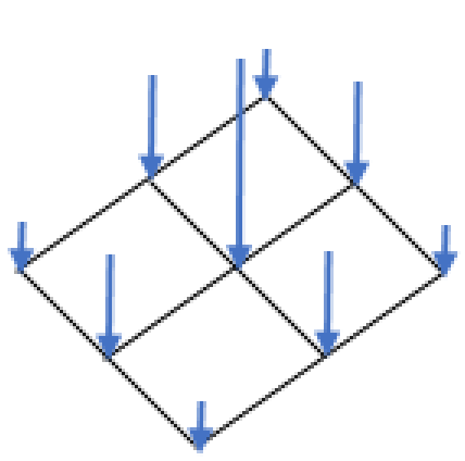
Fig. 7.1 Result of a unit pressure load.
7.7.2. Traction
BEGIN TRACTION
  #
  # surface set commands
  SURFACE|SIDESET|SIDE SET = <string list>surface_names
  REMOVE SURFACE = <string list>surface_names
  BLOCK = <string list> blocks
  ASSEMBLY = <string list> assemblies
  INCLUDE ALL BLOCKS
  #
  # specification commands
  DIRECTION = <string>direction_name
  FUNCTION = <string>function_name
  #
  # external traction sources
  READ VARIABLE = <string>var_name
  COPY VARIABLE = <string>var_name [FROM MODEL <string>model_name]
    MAP_BY_PROXIMITY|MAP_BY_ID(MAP_BY_PROXIMITY)
  COPY NEAREST ELEMENT|FACE|NODE <string>varName
    FROM MODEL <string>model_name
  TIME = <real>time|FIRST|LAST
  OBJECT TYPE = <string>FACE|NODE(FACE)
  #
  # user subroutine commands
  NODE SET SUBROUTINE = <string>subroutine_name
  SURFACE SUBROUTINE = <string>subroutine_name
  SUBROUTINE DEBUGGING OFF | SUBROUTINE DEBUGGING ON
  SUBROUTINE REAL PARAMETER: <string>param_name
    = <real>param_value
  SUBROUTINE INTEGER PARAMETER: <string>param_name
    = <integer>param_value
  SUBROUTINE STRING PARAMETER: <string>param_name
    = <string>param_value
  #
  # additional commands
  SCALE FACTOR = <real>scale_factor(1.0)
  ACTIVE PERIODS = <string list>period_names
  INACTIVE PERIODS = <string list>period_names
  #
  # surface integration schemes
  TRACTION INTEGRATION METHOD =
    NODAL_LUMPING|GAUSS_QUADRATURE
END [TRACTION]
The TRACTION command block applies a traction to each face in the associated surfaces. The traction has units of force per unit area. (A traction, unlike a pressure, may not necessarily be in the direction of the normal to the face to which it is applied.) The given traction is integrated over the surface area of a face.
The traction field can be determined by a SIERRA function or a user subroutine. If the traction field is constant over the faces and has only a time-varying component, the specification commands in the above command block can be used to specify the traction field. If the traction field has both time-varying and spatially varying components, a user subroutine is used to specify the traction field.
The traction force is integrated in the current deformed model configuration. The value of the traction force is the value of the traction field defined by this boundary condition times the face area. Thus if due to displacement a face grows or shrinks the net force produced by the traction boundary condition will change. As the traction field is defined explicitly with a direction a rotation of a face will not change the traction force on that face.
The traction field can only be controlled by one method. Accordingly, a TRACTION command block can only contain one of the options: function or user subroutine.
Currently, the TRACTION command block can be used for surfaces that have faces derived from solid elements (eight-node hexahedra, four-node tetrahedra, eight-node tetrahedra, etc.), membranes, and shells.
The TRACTION command block contains three groups of commands surface set, specification, and user subroutine. Each of these command groups is basically independent of the others. In addition to the command lines in the four command groups, there are three additional command lines: SCALE FACTOR, ACTIVE PERIODS, and INACTIVE PERIODS. The SCALE FACTOR command line can be used in conjunction with the specification commands or the user subroutine option. The ACTIVE PERIODS and INACTIVE PERIODS command lines are used to activate or deactivate this force boundary condition for certain time periods. Following are descriptions of the different command groups.
7.7.2.1. Surface Set Commands
The surface set commands portion of the TRACTION command block defines a set of surfaces associated with the traction field. The surface specification commands work the same as for the pressure boundary condition as described in section Section 7.7.1.1. Just as in the pressure boundary condition, assemblies may contain blocks, surfaces, or assemblies of these.
7.7.2.2. Traction Specification Commands
If the direction command is used, the traction vector at any given time is the same for all surfaces associated with the particular TRACTION command block. The direction of the traction vector is constant for all time; the magnitude of the traction vector may vary with time, however.
Following are the command lines used to specify the traction with a direction and a function:
DIRECTION = <string>defined_direction
FUNCTION = <string>function_name
The traction is specified in an arbitrary user-defined direction, and is defined using the DIRECTION command line. The name in the string defined_direction is a reference to a direction, which is defined using the DEFINE DIRECTION command block within the SIERRA scope. Note that the direction is always a unit vector, even if it is specified with a non-unit vector in the DEFINE DIRECTION command block.
The magnitude of the traction is specified by the FUNCTION command line. This references a function_name (defined in the SIERRA scope in a FUNCTION command block) that specifies the magnitude of the traction vector as a function of time. The magnitude can be scaled by use of the SCALE FACTOR command line described in Section 7.7.2.5.
7.7.2.3. User Subroutine Commands
If the user subroutine option is used, the traction vector may vary spatially at any given time for each of the surfaces associated with the particular TRACTION command block. The user subroutine option allows for a more complex description of the traction field than does the function option, but also requires writing a user subroutine to implement this capability.
A node set user subroutine will be used to define a traction at each node attached to a face which the boundary condition will be applied. This nodal traction is then integrated over the faces. A surface subroutine can be used to define a constant traction on each face. The subroutines will be called by Sierra/SM at the appropriate time to generate the traction field.
Following is the command line related to the user subroutine option:
NODE SET SUBROUTINE = <string>subroutine_name
SURFACE SUBROUTINE = <string>subroutine_name
SUBROUTINE DEBUGGING OFF | SUBROUTINE DEBUGGING ON
SUBROUTINE REAL PARAMETER: <string>param_name
  = <real>param_value
SUBROUTINE INTEGER PARAMETER: <string>param_name
  = <integer>param_value
SUBROUTINE STRING PARAMETER: <string>param_name
  = <string>param_value
The user subroutine option is invoked by using the NODE SET or SURFACE subroutine command lines. The string subroutine_name is the name of a FORTRAN subroutine that is written by the user. Associating traction values with nodes requires the use of a NODE SET SUBROUTINE command line. Associating traction values with faces requires the use of a NODE SET SUBROUTINE command line.
Following the NODE SET SUBROUTINE command line are other command lines that may be used to implement the user subroutine option. These command lines are described in Section 10.2.2.2 and consist of SUBROUTINE DEBUGGING OFF, SUBROUTINE DEBUGGING ON, SUBROUTINE REAL PARAMETER, SUBROUTINE INTEGER PARAMETER, and SUBROUTINE STRING PARAMETER. Examples of using these command lines are provided throughout Section 10.2.
The magnitude set in the user subroutine can be scaled by use of the SCALE FACTOR command line, as described in Section 7.7.2.5.
Usage requirements for the node set subroutine. The provided subroutine will return three values per node or face. Suppose the user subroutine provided passes the output values through an array output_values. For a given node inode, the output_values array would have the following values:
output_values(1,inode) = x component of traction vector
output_values(2,inode) = y component of traction vector
output_values(2,inode) = z component of traction vector
The values of the flags array are not used in the traction subroutine.
See Section 10.2 for more details on implementing the user subroutine option.
7.7.2.4. External Mesh Database Commands
The traction distribution may be defined by a field on the mesh database. When using a mesh database defined distribution the traction magnitude and/or direction is read from a finite element model defined via the FINITE ELEMENT MODEL command block described in Section 6.1. The finite element model is the model used by the region for its mesh definition as specified with the USE FINITE ELEMENT MODEL command (see Section 2.3).
READ VARIABLE = <string>var_name
COPY VARIABLE = <string>var_name [FROM MODEL <string>model_name]
  MAP_BY_PROXIMITY|MAP_BY_ID(MAP_BY_PROXIMITY)
COPY NEAREST ELEMENT|FACE|NODE <string>varName
  FROM MODEL <string>model_name
TIME = <real>time|FIRST|LAST
OBJECT TYPE = <string>FACE|NODE(FACE)
See Section 7.3.5 for more details.
Warning
At this time the COPY VARIABLE command can only be used with nodal variables. Neither the COPY VARIABLE command nor the READ VARIABLE command is compatible with global variables.
The OBJECT TYPE command line specifies whether the traction field on the mesh file is specified for nodes (the mesh object type is NODE) or for faces (the mesh object type is FACE). If the OBJECT TYPE command line is not present, it is assumed that the named variable is defined on faces.
The READ VARIABLE command gives the mesh file variable which defines the traction. There are two ways to define this traction field: the first, is to define a field with a single scalar value for each node or face and couple that with a DIRECTION command to define the traction direction; the second, is to define a vector field with three components. In the latter case, the field can define a unique traction magnitude and direction at each node or face. Furthermore, this option should not be used with the DIRECTION command.
The COPY VARIABLE command is a more flexible version of the READ VARIABLE command. This command allows a user to read a mesh variable from another mesh database and map it to another mesh by proximity or ID then use it to apply the traction.
If present, the TIME command defines the time slice in the input mesh file from which to read the traction field. If the TIME field is not present, the traction will be defined by interpolation between time slices closest to the current analysis time. Specifying the keyword FIRST or LAST will read from the first or last time slice in the input mesh file, respectively.
7.7.2.5. Additional Commands
These command lines in the TRACTION command block provide additional options for the boundary condition:
SCALE FACTOR = <real>scale_factor(1.0)
ACTIVE PERIODS = <string list>period_names
INACTIVE PERIODS = <string list>period_names
The SCALE FACTOR command line is used to apply an additional scaling factor, which is constant in both time and space, to all vector magnitude values of the field defined by the specification commands or the user subroutine. For example, if the magnitude of the traction in a time history function is given as 1.5 from time 1.0 to time 2.0 and the scale factor is 0.5, then the magnitude of the traction from time 1.0 to 2.0 is 0.75. The default value for the scale factor is 1.0.
The ACTIVE PERIODS and INACTIVE PERIODS command lines determine when the boundary condition is active. See Section 2.6 for more information about these command lines.
7.7.2.6. Surface Integration Schemes
TRACTION INTEGRATION METHOD =
  NODAL_LUMPING|GAUSS_QUADRATURE
By default, Sierra/SM will automatically choose the traction integration method. This input command can over-ride the default behavior for most face topologies. The exceptions are eight- and nine-noded quadrilateral faces (e.g., the faces of higher-order hexahedron elements), which always integrate tractions with full-order Gauss quadrature. For all other face topologies, the default traction calculation method is NODAL_LUMPING: the traction evaluated at the nodal coordinates is multiplied by an area attributed to that node to get the nodal force contribution. This default can be replaced by full-order Gauss quadrature for any face topology by specifying GAUSS_QUADRATURE as the traction integration method.
7.7.2.7. Example
DEFINE DIRECTION Fdir WITH VECTOR -1 0 -1

BEGIN FUNCTION One
  TYPE = CONSTANT
  BEGIN VALUES
    1.0
  END VALUES
END FUNCTION One

BEGIN TRACTION
 SURFACE = sideset_1
 DIRECTION = Fdir
 FUNCTION = One
 SCALE FACTOR =1
END TRACTION
This TRACTION applies a force vector with a magnitude of 1.0 time by the area associated with each node in sideset_1 as shown in Fig. 7.2. The force vectors are not required to be normal to the surface.
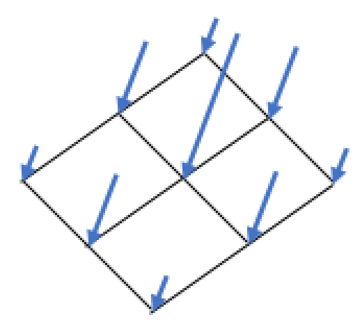
Fig. 7.2 Result of a unit traction load.
7.7.3. Prescribed Force
BEGIN PRESCRIBED FORCE
  #
  # node set commands
  NODE SET|NODESET = <string list>nodelist_names
  SURFACE|SIDESET|SIDE SET = <string list>surface_names
  BLOCK = <string list>block_names
  ASSEMBLY = <string list>assembly_names
  RIGID BODY = <string list>rigid_body_names
  INCLUDE ALL BLOCKS
  REMOVE NODE SET = <string list>nodelist_names
  REMOVE SURFACE = <string list>surface_names
  REMOVE BLOCK = <string list>block_names
  #
  # specification commands
  DIRECTION = <string>defined_direction |
    COMPONENT = <string>X|Y|Z
  FUNCTION = <string>function_name
  #
  # user subroutine commands
  NODE SET SUBROUTINE = <string>subroutine_name
  SUBROUTINE DEBUGGING OFF | SUBROUTINE DEBUGGING ON
  SUBROUTINE REAL PARAMETER: <string>param_name
    = <real>param_value
  SUBROUTINE INTEGER PARAMETER: <string>param_name
    = <integer>param_value
  SUBROUTINE STRING PARAMETER: <string>param_name
    = <string>param_value
  #
  # external force sources
  READ VARIABLE = <string>var_name
  COPY VARIABLE = <string>var_name [FROM MODEL <string>model_name]
    MAP_BY_PROXIMITY|MAP_BY_ID(MAP_BY_PROXIMITY)
  COPY NEAREST ELEMENT|FACE|NODE <string>varName
    FROM MODEL <string>model_name
  TIME = <real>time|FIRST|LAST
  OBJECT TYPE = <string>FACE|NODE(FACE)
  #
  # output external forces from pressure
  EXTERNAL FORCE CONTRIBUTION OUTPUT NAME =
    <string>variable_name

  #
  # additional commands
  SCALE FACTOR = <real>scale_factor(1.0)
  ACTIVE PERIODS = <string list>period_names
  INACTIVE PERIODS = <string list>period_names
END [PRESCRIBED FORCE]
The PRESCRIBED FORCE command block prescribes a force field for a given set of nodes. The force field associates a vector giving the magnitude and direction of the force with each node in the node set. The force field may vary over time and space. If the force field has only a time-varying component, the specification commands in the above command block can be used to specify the force field. If the force field has both time-varying and spatially varying components, a user subroutine is used to specify the force field. In a given boundary condition command block, commands from only one of the command groups (specification commands or user subroutine commands) may be used.
The PRESCRIBED FORCE command block contains three groups of commands—node set, function, and user subroutine. Each of these command groups is basically independent of the others. In addition to the command lines in the three command groups, there are three additional command lines: SCALE FACTOR, ACTIVE PERIODS, and INACTIVE PERIODS. The SCALE FACTOR command line can be used in conjunction with either the specification commands or the user subroutine commands. The ACTIVE PERIODS and INACTIVE PERIODS command lines are used to activate or deactivate this force boundary condition for certain time periods. Following are descriptions of the different command groups.
7.7.3.1. Node Set Commands
The node set commands portion of the PRESCRIBED FORCE command block defines a set of nodes associated with the prescribed force field and can include some combination of the following command lines:
NODE SET|NODESET = <string list>nodelist_names
SURFACE|SIDESET|SIDE SET = <string list>surface_names
BLOCK = <string list>block_names
ASSEMBLY = <string list>assembly_names
RIGID BODY = <string list>rigid_body_names
INCLUDE ALL BLOCKS
REMOVE NODE SET = <string list>nodelist_names
REMOVE SURFACE = <string list>surface_names
REMOVE BLOCK = <string list>block_names
These command lines, taken collectively, constitute a set of Boolean operators for constructing a set of nodes. See Section 7.1.1 for more information about the use of these command lines for creating a set of nodes used by the boundary condition. There must be at least one NODE SET|NODESET, SURFACE, BLOCK, ASSEMBLY, or INCLUDE ALL BLOCKS command line in the command block. Assemblies may contain blocks, surfaces, nodesets, or assemblies of these.
7.7.3.2. Specification Commands
If the specification commands are used, the force vector at any given time is the same for all nodes in the node set associated with the particular PRESCRIBED FORCE command block. The direction of the force vector is constant for all time; the magnitude of the force vector may vary with time, however.
Following are the command lines used to specify the prescribe force with a direction and a function:
DIRECTION = <string>defined_direction |
  COMPONENT = <string>X|Y|Z
FUNCTION = <string>function_name
The force can be specified either along an arbitrary user-defined direction or along a component direction (X, Y, or Z), but not both.
The
DIRECTIONcommand line is used to prescribe force in an arbitrary user-defined direction. The name in the stringdefined_directionis a reference to a direction, which is defined using theDEFINE DIRECTIONcommand block within the SIERRA scope.The
COMPONENTcommand line specifies that the force vector lies along one of the component directions. TheCOMPONENTcommand line is a shortcut to an internally defined direction vector; for example, componentxcorresponds to using direction vector (1, 0, 0).
The magnitude of the force is specified by the FUNCTION command line. This references a function_name (defined in the SIERRA scope in a FUNCTION command block) that specifies the magnitude of the force vector as a function of time. The magnitude can be scaled by use of the SCALE FACTOR command line described in Section 7.7.3.6.
The force is applied only in the prescribed direction, and is not applied in any direction orthogonal to that direction.
7.7.3.3. User Subroutine Commands
If the user subroutine option is used, the force vector may vary spatially at any given time for each of the nodes in the node set associated with the particular PRESCRIBED FORCE command block. The user subroutine option allows for a more complex description of the force field than does the function option, but also requires writing a user subroutine to implement this capability. The user subroutine will be used to define a force direction and a magnitude for every node to which the boundary condition will be applied. The subroutine will be called by Sierra/SM at the appropriate time to generate the force field.
Following are the command lines related to the user subroutine option:
NODE SET SUBROUTINE = <string>subroutine_name
SUBROUTINE DEBUGGING OFF | SUBROUTINE DEBUGGING ON
SUBROUTINE REAL PARAMETER: <string>param_name
  = <real>param_value
SUBROUTINE INTEGER PARAMETER: <string>param_name
  = <integer>param_value
SUBROUTINE STRING PARAMETER: <string>param_name
  = <string>param_value
The user subroutine option is invoked by using the NODE SET SUBROUTINE command line. The string subroutine_name is the name of a FORTRAN subroutine that is written by the user.
Following the NODE SET SUBROUTINE command line are other command lines that may be used to implement the user subroutine option. These command lines are described in Section 10.2.2.2 and consist of SUBROUTINE DEBUGGING OFF, SUBROUTINE DEBUGGING ON, SUBROUTINE REAL PARAMETER, SUBROUTINE INTEGER PARAMETER, and SUBROUTINE STRING PARAMETER. Examples of using these command lines are provided throughout Section 10.2.
The magnitude set in the user subroutine can be scaled by use of the SCALE FACTOR command line, as described in Section 7.7.3.6.
Usage requirements for the node set subroutine. The provided subroutine will return three output values per node. Suppose a user subroutine is provided that passes the output values through an array output_values. For a given node inode, the output_values array would have the following values:
output_values(1,inode) = x component of force at inode
output_values(2,inode) = y component of force at inode
output_values(3,inode) = z component of force at inode
The three components of the force vector are given in output_values 1 through 3. The values of the flags array are ignored.
See Section 10.2 for more details on implementing the user subroutine option.
7.7.3.4. External Mesh Database Commands
The prescribed force may be defined by a field on the mesh database. When using a mesh database defined force the magnitude and/or direction is read from a finite element model defined via the FINITE ELEMENT MODEL command block described in Section 6.1. The finite element model is the model used by the region for its mesh definition as specified with the USE FINITE ELEMENT MODEL command (see Section 2.3).
READ VARIABLE = <string>var_name
COPY VARIABLE = <string>var_name [FROM MODEL <string>model_name]
TIME = <real>time|FIRST|LAST
OBJECT TYPE = <string>FACE|NODE(FACE)
See Section 7.3.5 for more details.
The OBJECT TYPE command line specifies whether the traction field on the mesh file is specified for nodes (the mesh object type is NODE) or for faces (the mesh object type is FACE). If the OBJECT TYPE command line is not present, it is assumed that the named variable is defined on faces.
The READ VARIABLE command gives the mesh file variable which defines the force. There are two ways to define this force field: the first, is to define a field with a single scalar value for each node or face and couple that with a DIRECTION command to define the direction of the force; the second, is to define a vector field with three components. In the latter case, the field can define a unique traction magnitude and direction at each node or face. Furthermore, this option should not be used with the DIRECTION command.
The COPY VARIABLE command is a more flexible version of the READ VARIABLE command. This command allows a user to read a mesh variable from another mesh database and map it to another mesh by proximity or ID then use it to apply the force.
If present, the TIME command defines the time slice in the input mesh file from which to read the force field. If the TIME field is not present, the force will be defined by interpolation between time slices closest to the current analysis time. Specifying the keyword FIRST or LAST will read from the first or last time slice in the input mesh file, respectively.
7.7.3.5. Output Command
This command line lets the user create a variable that stores information about the contribution to the external force vector at a node arising solely from a prescribed force:
EXTERNAL FORCE CONTRIBUTION OUTPUT NAME =
  <string>variable_name
If the above command line appears in a PRESCRIBED FORCE command block, then there will be a variable created with whatever name the user specifies for variable_name. The variable defines a three-dimensional vector at each node associated with this particular command block. The three-dimensional vector at each node represents the external force due solely to the prescribed force on the elements attached to that node. For example, if one of the nodes associated with this particular command block has four elements attached to it and each element has a prescribed force, then the external force contribution at the node would be summed from the prescribed force for all four elements.
Once this variable for the external force contribution from a precribed force is specified, it may be used like any other nodal variable. The user can, for example, specify the variable as a nodal variable to be output in a RESULTS OUTPUT command block. Or the user can reference the variable in a user subroutine.
7.7.3.6. Additional Commands
These command lines in the PRESCRIBED FORCE command block provide additional options for the boundary condition:
SCALE FACTOR = <real>scale_factor(1.0)
ACTIVE PERIODS = <string list>period_names
INACTIVE PERIODS = <string list>period_names
The SCALE FACTOR command line is used to apply an additional scaling factor, which is constant in both time and space, to all vector magnitude values of the field defined by the specification commands or the user subroutine. For example, if the magnitude of the force in a time history function is given as 1.5 from time 1.0 to time 2.0 and the scale factor is 0.5, then the magnitude of the force from time 1.0 to 2.0 is 0.75. The default value for the scale factor is 1.0.
The ACTIVE PERIODS and INACTIVE PERIODS command lines determine when the boundary condition is active. See Section 2.6 for more information about these command lines.
7.7.3.7. Example
DEFINE DIRECTION Fdir WITH VECTOR -1 0 -1

BEGIN FUNCTION One
  TYPE = CONSTANT
  BEGIN VALUES
    1.0
  END VALUES
END FUNCTION One


BEGIN PRESCRIBED FORCE
 SURFACE = sideset_1
 DIRECTION = Fdir
 FUNCTION = One
 SCALE FACTOR =1
END PRESCRIBED FORCE
The resulting PRESCRIBED FORCE applies a force vector of magnitude 1.0 to each node in sideset_1 as shown in Fig. 7.3.
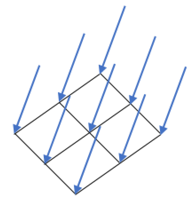
Fig. 7.3 Result of a unit prescribed force.
7.7.4. Prescribed Moment
BEGIN PRESCRIBED MOMENT
  #
  # node set commands
  NODE SET|NODESET = <string list>nodelist_names
  SURFACE|SIDESET|SIDE SET = <string list>surface_names
  BLOCK = <string list>block_names
  ASSEMBLY = <string list>assembly_names
  RIGID BODY = <string list>rigid_body_names
  INCLUDE ALL BLOCKS
  REMOVE NODE SET = <string list>nodelist_names
  REMOVE SURFACE = <string list>surface_names
  REMOVE BLOCK = <string list>block_names
  #
  # specification commands
  DIRECTION = <string>defined_direction |
    COMPONENT = <string>X|Y|Z
  FUNCTION = <string>function_name
  #
  # user subroutine commands
  NODE SET SUBROUTINE = <string>subroutine_name
  SUBROUTINE DEBUGGING OFF | SUBROUTINE DEBUGGING ON
  SUBROUTINE REAL PARAMETER: <string>param_name
    = <real>param_value
  SUBROUTINE INTEGER PARAMETER: <string>param_name
    = <integer>param_value
  SUBROUTINE STRING PARAMETER: <string>param_name
    = <string>param_value
  #
  # additional commands
  SCALE FACTOR = <real>scale_factor(1.0)
  ACTIVE PERIODS = <string list>period_names
  INACTIVE PERIODS = <string list>period_names
END [PRESCRIBED MOMENT]
The PRESCRIBED MOMENT command block prescribes a moment field for a given set of nodes. Moments can only be defined for nodes with rotational degrees of freedom. This includes nodes attached to beam and shell elements, rigid body nodes, and potentially superelement nodes.
The moment field associates a vector giving the magnitude and direction of the moment with each node in the set. If the moment field has only a time-varying component, the specification commands in the above command block can be used to specify the moment field. If the moment field has both time-varying and spatially varying components, a user subroutine option is used to specify the moment field. In a given boundary condition command block, commands from only one of the command groups (specification commands or user subroutine commands) may be used.
The PRESCRIBED MOMENT command block contains three groups of commands—node set, function, and user subroutine. Each of these command groups is basically independent of the others. In addition to the command lines in the four command groups, there are three additional command lines: SCALE FACTOR, ACTIVE PERIODS, and INACTIVE PERIODS. The SCALE FACTOR command line can be used in conjunction with either the specification commands or the user subroutine commands. The ACTIVE PERIODS and INACTIVE PERIODS command lines are used to activate or deactivate this force boundary condition for certain time periods. Following are descriptions of the different command groups.
7.7.4.1. Node Set Commands
The node set commands portion of the PRESCRIBED MOMENT command block
defines a set of nodes associated with the prescribed moment field and can
include some combination of the following command lines:
NODE SET|NODESET = <string list>nodelist_names
SURFACE|SIDESET|SIDE SET = <string list>surface_names
BLOCK = <string list>block_names
ASSEMBLY = <string list>assembly_names
INCLUDE ALL BLOCKS
REMOVE NODE SET = <string list>nodelist_names
REMOVE SURFACE = <string list>surface_names
REMOVE BLOCK = <string list>block_names
These command lines, taken collectively, constitute a set of Boolean operators for constructing a set of nodes. See Section 7.1.1 for more information about the use of these command lines for creating a set of nodes used by the boundary condition. There must be at least one NODE SET|NODESET, SURFACE, BLOCK, ASSEMBLY, or INCLUDE ALL BLOCKS command line in the command block. Assemblies may contain blocks, surfaces, nodesets, or assemblies of these.
7.7.4.2. Specification Commands
If the specification commands are used, the moment vector at any given time is the same for all nodes in the node set associated with the particular PRESCRIBED MOMENT command block. The direction of the moment vector is constant for all time; the magnitude of the moment vector may vary with time, however.
Following are the command lines used to specify the prescribed moment with a function and a direction:
DIRECTION = <string>defined_direction |
  COMPONENT = <string>X|Y|Z
FUNCTION = <string>function_name
The moment can be specified either along an arbitrary user-defined direction or along a component direction (X, Y, or Z), but not both.
The
DIRECTIONcommand line is used to prescribe the moment in an arbitrary user-defined direction. The name in the stringdefined_directionis a reference to a direction, which is defined using theDEFINE DIRECTIONcommand block within the SIERRA scope.The
COMPONENTcommand line specifies that the moment vector lies along one of the component directions. TheCOMPONENTcommand line is a shortcut to an internally defined direction vector; for example, componentxcorresponds to using direction vector (1, 0, 0).
The magnitude of the moment is specified by the FUNCTION command line. This references a function_name (defined in the SIERRA scope in a FUNCTION command block) that specifies the magnitude of the moment vector as a function of time. The magnitude can be scaled by use of the SCALE FACTOR command line described in Section 7.7.4.4.
The moment is applied only in the prescribed direction, and is not applied in any direction orthogonal to that direction.
7.7.4.3. User Subroutine Commands
If the user subroutine option is used, the moment vector may vary spatially at any given time for each of the nodes in the node set associated with the particular PRESCRIBED MOMENT command block. The user subroutine option allows for a more complex description of the moment field than do specification commands, but also requires writing a user subroutine to implement this capability. The user subroutine will be used to define a moment direction and a magnitude for every node to which the boundary condition will be applied. The subroutine will be called by Sierra/SM at the appropriate time to generate the moment field.
Following are the command lines related to the user subroutine option:
NODE SET SUBROUTINE = <string>subroutine_name
SUBROUTINE DEBUGGING OFF | SUBROUTINE DEBUGGING ON
SUBROUTINE REAL PARAMETER: <string>param_name
  = <real>param_value
SUBROUTINE INTEGER PARAMETER: <string>param_name
  = <integer>param_value
SUBROUTINE STRING PARAMETER: <string>param_name
  = <string>param_value
The user subroutine option is invoked by using the NODE SET SUBROUTINE command line. The string subroutine_name is the name of a FORTRAN subroutine that is written by the user.
Following the NODE SET SUBROUTINE command line are other command lines that may be used to implement the user subroutine option. These command lines are described in Section 10.2.2.2 and consist of SUBROUTINE DEBUGGING OFF, SUBROUTINE DEBUGGING ON, SUBROUTINE REAL PARAMETER, SUBROUTINE INTEGER PARAMETER, and SUBROUTINE STRING PARAMETER. Examples of using these command lines are provided throughout Section 10.2.
The magnitude set in the user subroutine can be scaled by use of the SCALE FACTOR command line, as described in Section 7.7.4.4.
Usage requirements for the node set subroutine. The provided subroutine will return three output values per node. Suppose a provided user subroutine passes the output values through an array output_values. For a given node inode, the output_values array would have the following values:
output_values(1,inode) = moment about x-direction at inode
output_values(2,inode) = moment about y-direction at inode
output_values(3,inode) = moment about z-direction at inode
The three components of the moment vector are given in output_values 1 through 3. The values of the flags array are ignored.
See Section 10.2 for more details on implementing the user subroutine option.
7.7.4.4. Additional Commands
These command lines in the PRESCRIBED MOMENT command block provide additional options for the boundary condition:
SCALE FACTOR = <real>scale_factor(1.0)
ACTIVE PERIODS = <string list>period_names
INACTIVE PERIODS = <string list>period_names
The SCALE FACTOR command line is used to apply an additional scaling factor, which is constant in both time and space, to all vector magnitude values of the field defined by the specification commands or the user subroutine. For example, if the magnitude of the moment in a time history function is given as 1.5 from time 1.0 to time 2.0 and the scale factor is 0.5, then the magnitude of the moment from time 1.0 to 2.0 is 0.75. The default value for the scale factor is 1.0.
The ACTIVE PERIODS and INACTIVE PERIODS command lines determine when the boundary condition is active. See Section 2.6 for more information about these command lines.
7.7.5. Drag Force
BEGIN DRAG FORCE
  #
  # surface set commands
  BLOCK = <string list>block_names
  SURFACE = <string list>surface_names
  ASSEMBLY = <string list>assembly_names
  RIGID BODY = <string list>rigid_body_names
  INCLUDE ALL BLOCKS
  # specification commands
  COMPUTE ON FRAGMENTS
  DENSITY OF FLUID = <real>fluid_density
  DRAG COEFFICIENT = <real>drag_coefficient
    DRAG AREA TYPE = PROJECTED_AREA | VOLUME (PROJECTED_AREA)
    [= <real>projected_area/volume]
    # output external forces from drag force
  EXTERNAL FORCE CONTRIBUTION OUTPUT NAME = <string>force_name
END
Drag force boundary conditions are used to model the effect of the fluid medium on fragment flight. This boundary condition is currently limited to application on fragments. Drag force \(\mathbf{F}_D\) is computed as
where the fluid density \(\rho_f\) and the drag coefficient \(C_D\) are user specified parameters. The area vector \(\mathbf{A}\) is the exposed surface area projected in the direction of the average fragment velocity \(\mathbf{v}\).
The DRAG FORCE command block contains three groups of commands – node set, specification, and output external forces. Each of these command groups is basically independent of the others. Following are descriptions of the different command groups.
7.7.5.1. Surface Set Commands
The surface set commands portion of the DRAG FORCE command block defines a set of nodes associated with the drag force field and can include some combination of the following command lines:
BLOCK = <string list>block_names
SURFACE = <string list>surface_names
ASSEMBLY = <string list>assembly_names
RIGID BODY = <string list>rigid_body_names
INCLUDE ALL BLOCKS
These command lines, taken collectively, constitute a set of Boolean operators for constructing a set of surfaces. See Section 7.1.1 for more information about the use of these command lines for creating a set of surfaces used by the boundary condition. There must be at least one BLOCK, SURFACE, ASSEMBLY, RIGID BODY, or INCLUDE ALL BLOCKS command line in the command block. Assemblies may contain blocks, surfaces, or assemblies of these. Rigid bodies must be comprised of surfaces. Thus, they must be made of blocks, and not just nodes coming from sidesets or nodesets.
7.7.5.2. Specification Commands
The following are the specification commands, used in specifying the parameters for the drag force calculation in (7.1).
COMPUTE ON FRAGMENTS
DENSITY OF FLUID = <real>fluid_density
DRAG COEFFICIENT = <real>drag_coefficient
  DRAG AREA TYPE = PROJECTED_AREA | VOLUME (PROJECTED_AREA)
    [= <real>projected_area/volume]
The COMPUTE ON FRAGMENTS line command specifies if the drag force should be applied to fragments computed via the BEGIN IDENTIFY FRAGMENTS command.
The DENSITY OF FLUID line command lets the user specify the fluid density for \(\rho_f\) in (7.1).
The DRAG COEFFICIENT line command is used to define the value for \(C_D\) in (7.1).
The optional DRAG AREA TYPE line command determines how the projected area is calculated. Choosing the VOLUME option sets the fragment’s projected area to \(\mathrm{volume}^{\frac{2}{3}}\), see [[1]]. Specifying PROJECTED_AREA calculates the projected area. The projected area and volume are either calculated internally (default option) or can be set with the optional command = <real>area/volume at the end of DRAG AREA TYPE. This optional command will set either the projected area or the volume used in the drag force calculation.
7.7.5.3. Output Command
This command line lets the user create a variable that stores information about the contribution to the external force vector at a node arising solely from drag force:
EXTERNAL FORCE CONTRIBUTION OUTPUT NAME =
  <string>variable_name
If the above command line appears in a DRAG FORCE command block, then there will be a variable created with the user-specified variable name in variable_name. The variable defines a three-dimensional vector at each node associated with this particular command block. The three-dimensional vector at each node represents the external force due solely to the drag force on the elements attached to that node. For example, if one of the nodes associated with this particular command block has elements attached to it and each element has a drag force load, then the external force contribution at the node would be summed from the drag force load for all four elements.
Once this variable for the external force contribution from a drag force load is specified, it may be used like any other nodal variable. The user can, for example, specify the variable as a nodal variable to be output in a RESULTS OUTPUT command block. Additionally the user can reference the variable in a user subroutine.
7.7.5.4. Examples
With the command block below, the drag force calculation below would compute the drag force on fragments. It would set the density of the fluid to 1.0e-4 and the drag coefficient to a value of 0.5. Setting the drag area type to projected area and including a value would set the projected area to 1.0. Not setting the value would make it use the default internal projected area calculation.
BEGIN DRAG FORCE
  INCLUDE ALL BLOCKS
  COMPUTE ON FRAGMENTS
  DENSITY OF FLUID = 1.0e-4
  DRAG COEFFICIENT = 0.5
  DRAG AREA TYPE = PROJECTED AREA = 1.0
  EXTERNAL FORCE CONTRIBUTION OUTPUT NAME = force_drag
END DRAG FORCE
Specifying volume for the drag area type and a value would set the volume to 1.0. Omitting the value would use the internal volume calculation. In either event, the projected area would be calculated from \(\mathrm{volume}^{\frac{2}{3}}\).
BEGIN DRAG FORCE
  INCLUDE ALL BLOCKS
  COMPUTE ON FRAGMENTS
  DENSITY OF FLUID = 1.0e-4
  DRAG COEFFICIENT = 0.5
  DRAG AREA TYPE = VOLUME = 1.0
  EXTERNAL FORCE CONTRIBUTION OUTPUT NAME = force_drag
END DRAG FORCE