12.1. A. Explicit Dynamics Example Problem
This chapter provides an example problem to illustrate the construction of an input file for an analysis. The example problem consists of 124 spheres made of lead enclosed in a steel box. The steel box has an open top into which a steel plate is placed (see Fig. 12.1). A prescribed velocity is then applied on the steel plate, pushing it into the box and crushing the spheres contained within using frictionless contact. This problem is a severe test for the contact algorithms as the spheres crush into a nearly solid block. See Fig. 12.2 for results of this problem.
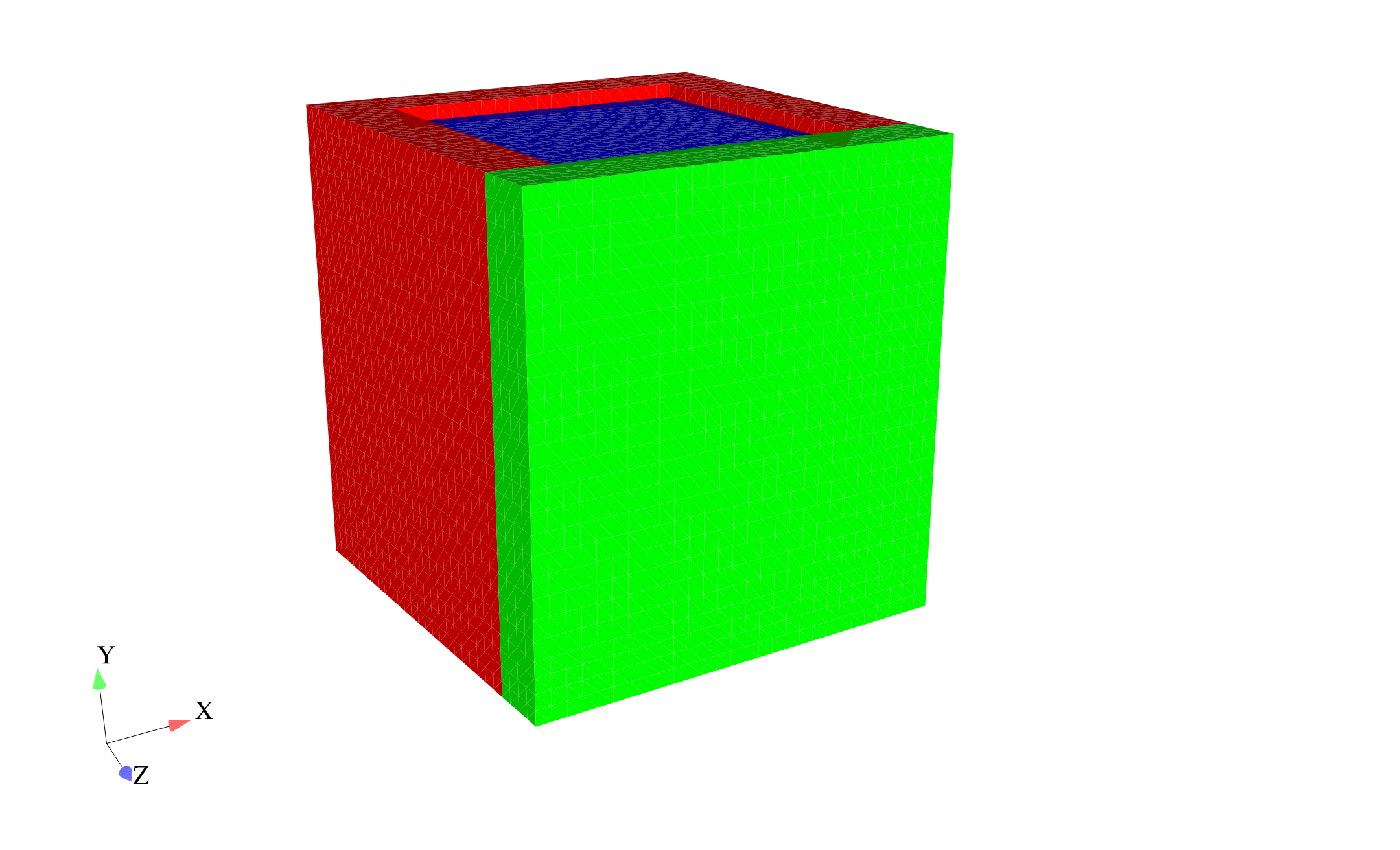 (a) Undeformed mesh.
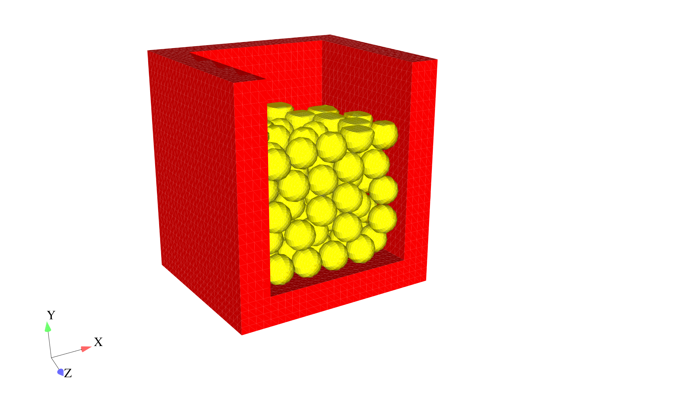 (b) Initial crush of spheres.
Fig. 12.1 Mesh for example problem: (a) box (red and green surfaces) with plate in top (blue surface) and (b) mesh with blue and green surfaces removed to show internal spheres (yellow) with initial crush.
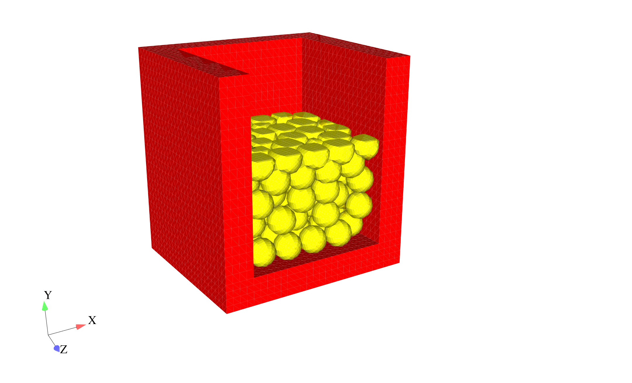 (a) Additional crush of spheres.
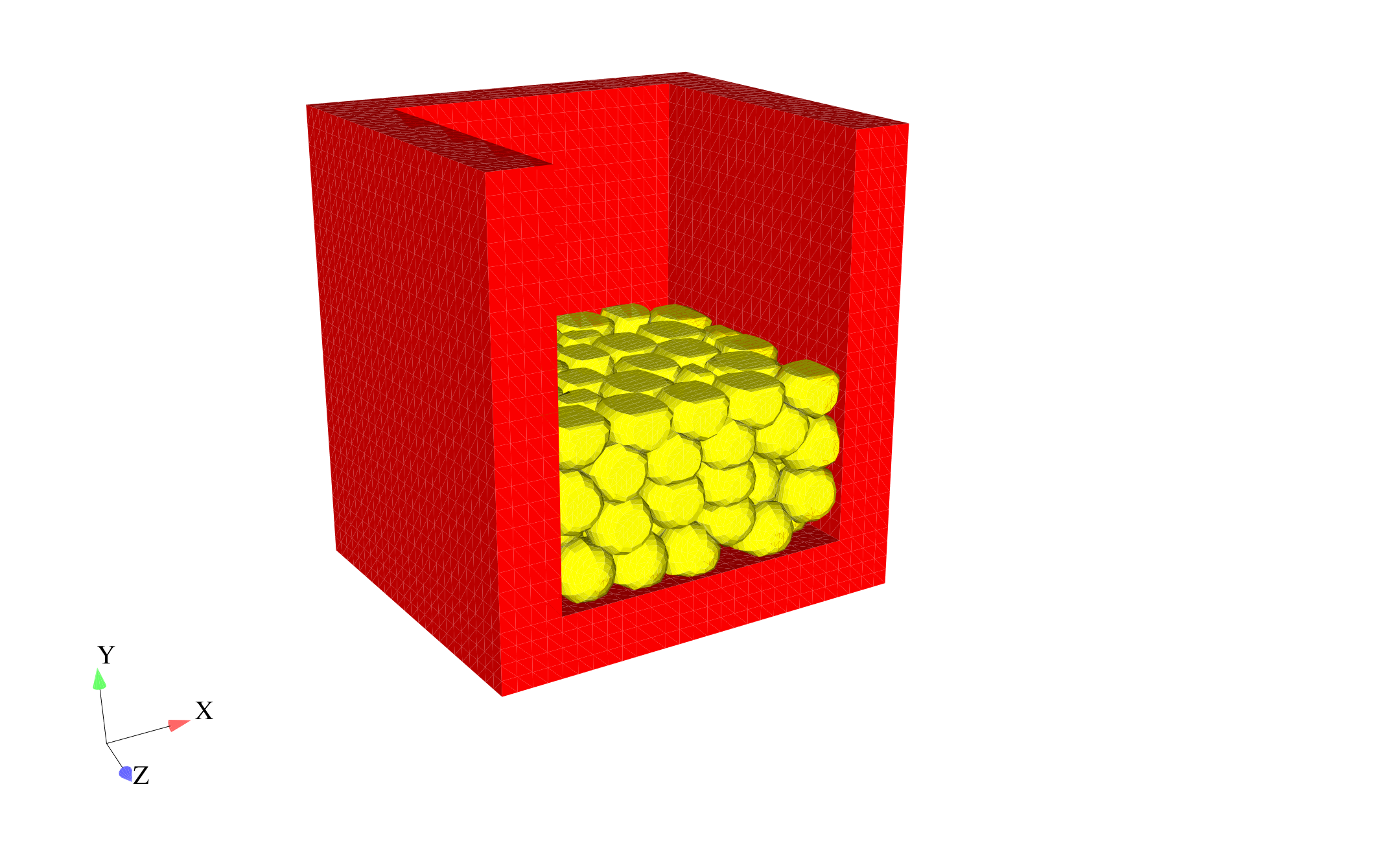 (b) Final deformed configuration.
Fig. 12.2 Mesh with blue and green surfaces removed to show internal spheres (yellow) after initial crush shown in Fig. 12.1 (b).
The input file is described below, with comments to explain every few lines. Following the description, the full input file is listed again. Most of the key words in this example are all lowercase, which is different from the convention we have used to describe the command lines in this document. However, all the lowercase usage in the next example is an acceptable format in Presto.
The input file starts with a begin sierra statement (i.e., the first line of the SIERRA command block), as is required for all input files:
begin sierra crush_124_spheres
We now need to define the functions used with this problem. The boundary conditions require a function for the initial velocity, as follows:
begin function constant_velocity
  type is piecewise linear
  ordinate is velocity
  abscissa is time
  begin values
    0.0 30.0
    1.0 30.0
  end values
end
To define the boundary conditions, we need to define the direction for the initial velocity – this is in the \(y\)-direction. We could also choose to specify the Y component for the initial condition, but this input file uses directions.
define direction y_axis with vector 0.0 1.0 0.0
Next we define the material models used for this analysis. This problem has two materials: steel for the box, and lead for the spheres. Both materials use the elastic-plastic material model (denoted as elastic_plastic).
begin material steel
  density = 7871.966988

  begin parameters for model elastic_plastic
    youngs modulus = 1.999479615e+11
    poissons ratio = 0.33333
    yield stress = 275790291.7
    hardening modulus = 275790291.7
    beta = 1.0
  end parameters for model elastic_plastic

end material steel

begin material lead
  density = 11253.30062

  begin parameters for model elastic_plastic
    youngs modulus = 1.378951459e+10
    poissons ratio = 0.44
    yield stress = 13789514.59
    hardening modulus = 0.0
    beta = 1.0
  end parameters for model elastic_plastic

end material lead
Now we define the finite element mesh. This includes specification of the file that contains the mesh, and a list of all the element blocks we will use from the mesh and the material associated with each block. The name of the file is crush_124_spheres.g. The specification of the database type is optional—ExodusII is the default. Currently, each element block must be defined individually. For this particular problem, all the spheres are the same element block. Each sphere is a distinct geometry entity, but all spheres constitute one element block in the Exodus II database. The three element blocks that make up the box and lid all reference the same material description. The material description is not repeated three times. The material description for steel appears once and is then referenced three times.
begin finite element model mesh1
  Database Name = crush_124_spheres.g
  Database Type = exodusII

  begin parameters for block block_1
    material = steel
    model =  elastic_plastic
  end parameters for block block_1

  begin parameters for block block_2
    material = steel
    model =  elastic_plastic
  end parameters for block block_2

  begin parameters for block block_3
    material = steel
    model =  elastic_plastic
  end parameters for block block_3

  begin parameters for block block_4
    material = lead
    model =  elastic_plastic
  end parameters for block block_4

end finite element model mesh1
As an alternative to referencing the material description for steel three times as done above, you could define multiple element blocks simultaneously on the same command line. Thus, the three element block specifications with the material steel could be consolidated into one, as follows:
begin parameters for block block_1 block_2 block_3
  material = steel
  model =  elastic_plastic
end parameters for block block_1 block_2 block_3
At this point we have finished specifying physics-independent quantities. We now want to set up the Presto procedure and region, along with the time control command block. We start by defining the beginning of the procedure scope, the time control command block, and the beginning of the region scope. Only one time stepping block command block is needed for this analysis. The termination time is set to \(7 \times 10^{-4}\).
begin presto procedure Apst_Procedure

begin time control
  begin time stepping block p1
    start time = 0.0
    begin parameters for presto region presto
      time step scale factor = 1.0
      time step increase factor = 2.0
      step interval = 25
    end parameters for presto region presto
  end time stepping block p1

  termination time = 7.0e-4
end time control

  begin presto region presto
Next we associate the finite element model we defined above (mesh1) with this presto region.
use finite element model mesh1
Now we define the boundary conditions on the problem. We prescribe the velocity on the top surface of the box (nodelist_100) to crush the spheres, and we confine the bottom surface of the box (nodelist_200) not to move. Although we use node sets to define these boundary conditions, we could have used the corresponding side sets.
begin prescribed velocity
  node set = nodelist_100
  direction = y_axis
  function = constant_velocity
  scale factor = -1.0
end

begin fixed displacement
  node set = nodelist_200
  components = Y
end
Now we define the contact for this problem. For this problem, we want all four element blocks to be able to contact each other. In this case, we define the same contact characteristics for all interactions. Since no friction model is defined in the block below, the contact defaults to frictionless contact. (Numerous options exist to control the contact algorithm. The options you choose will affect contact algorithm efficiency and solution accuracy. See Section 8 to determine how to set input for the CONTACT DEFINITION command block to obtain the best level of efficiency and accuracy for your particular problem.)
begin contact definition
  skin all blocks = on
  begin interaction defaults
    general contact = on
    self contact = on
  end
end
Now we define what variables we want in the results file and how often we want this file to be written. Here we request files written every \(7 \times 10^{-6}\) sec of analysis time. This will result in results output at one hundred time steps (plus the zero time step) since the termination time is set to \(7 \times 10^{-4}\) sec. The output file will be called crush_124_spheres.e, and it will be an Exodus II file (the database type command is optional; it defaults to ExodusII). The variables we are requesting are the displacements and external forces at the nodes, the rotated stresses for the elements, the time step increment, and the kinetic energy.
begin Results Output output_presto
  Database Name = crush_124_spheres.e
  Database Type = exodusII
  At Time 0.0, Increment = 7.0e-6
  nodal displacement as displ
  nodal force_external as fext
  element stress as stress
  global KineticEnergy as KE
  global timestep
end
Now we end the presto region, presto procedure, and sierra blocks to complete the input file.
    end presto region presto
  end presto procedure Apst_Procedure
end sierra crush_124_spheres
Here is the resulting full input file for this problem:
begin sierra crush_124_spheres
  begin function constant_velocity
    type is piecewise linear
    ordinate is velocity
    abscissa is time
    begin values
      0.0 30.0
      1.0 30.0
    end values
  end function constant_velocity
  define direction y_axis with vector 0.0 1.0 0.0

  begin material steel
    density = 7871.966988

    begin parameters for model elastic_plastic
      youngs modulus = 1.999479615e+11
      poissons ratio = 0.33333
      yield stress = 275790291.7
      hardening modulus = 275790291.7
      beta = 1.0
    end parameters for model elastic_plastic

  end material steel

  begin material lead
    density = 11253.30062

    begin parameters for model elastic_plastic
      youngs modulus = 1.378951459e+10
      poissons ratio = 0.44
      yield stress = 13789514.59
      hardening modulus = 0.0
      beta = 1.0
    end parameters for model elastic_plastic

  end material lead

  begin finite element model mesh1
    Database Name = crush_124_spheres.g
    Database Type = exodusII

    begin parameters for block block_1
      material = steel
      model =  elastic_plastic
    end parameters for block block_1

    begin parameters for block block_2
      material = steel
      model =  elastic_plastic
    end parameters for block block_2

    begin parameters for block block_3
      material = steel
      model =  elastic_plastic
    end parameters for block block_3

    begin parameters for block block_4
      material = lead
      model =  elastic_plastic
    end parameters for block block_4

  end finite element model mesh1

  begin presto procedure Apst_Procedure

    begin time control
      begin time stepping block p1
        start time = 0.0
        begin parameters for presto region presto
          time step scale factor = 1.0
          time step increase factor = 2.0
          step interval = 25
        end parameters for presto region presto
      end time stepping block p1

      termination time = 7.0e-4
    end time control

    begin presto region presto

      use finite element model mesh1

      begin prescribed velocity
        node set = nodelist_100
        direction = y_axis
        function = constant_velocity
        scale factor = -1.0
      end prescribed velocity

      begin fixed displacement
        node set = nodelist_200
        components = Y
      end fixed displacement

      begin contact definition
        skin all blocks = on
        begin interaction defaults
          general contact = on
          self contact = on
        end
      end

      begin Results Output output_presto
        Database Name = crush_124_spheres.e
        Database Type = exodusII
        At Time 0.0, Increment = 7.0e-6
        nodal displacement as displ
        nodal force_external as fext
        element stress as stress
        global KineticEnergy as KE
        global timestep
      end results output output_presto

    end presto region presto
  end presto procedure Apst_Procedure
end sierra crush_124_spheres