10.5. User Subroutine Library
Many user subroutines are used commonly and have been permanently incorporated into the code. These subroutines are used just like any other subroutines, but they do not need to be manually compiled into the code. (The user need be concerned only about the Sierra/SM command lines.) Additionally the subroutines listed here are regularly tested with Sierra/SM and formally maintained by the development team.
This section describes the usage of each of these user subroutine library subroutines.
10.5.1. aupst_preload_solver
Author: Nathan Crane
Note, use of the ‘aupst_preload_solver’ subroutine is also documented in the example manual chapter ‘Automated Adaptive Preloading.’
Purpose:
This subroutine is used to solve simple inverse problems for preload conditions determining the value of a working variable to achieve some target condition. Examples where this subroutine has been successfully used include: apply the target strain in bolts to yield specified clamping force in each bolt, find the force that must be applied to a pin to reach a target displacement in that pin, and to find the displacement at a fixture to yield a target contact force on a body.
There are a number of restrictions on the relations that can be effectively solved by this subroutine. The first is that the relationship is monotonic. For example adding more strain to bolt increases the clamping force. If the relationship is not monotonic the solution may stall at a local maximum. The second restriction is that the relationship is at least somewhat smooth. The relationship between changes in the working variable to the target condition does not need to be linear, but should be at least nominally \(C^0\) continuous. Third the relationship must be somewhat strong. Again as an example changing the artificial strain in a bolt strongly affects its clamping force.
The subroutine itself is generally called by a USER OUTPUT command block and often needs to be combined with a number of other commands as shown in this example:
#  Drive element preload as a variable set by
#  aupst_preload_solver subroutine
begin function bolt_preload
  type is analytic
  expression variable: v = element applied_strain
  evaluate expression = "v"
end
#  Internal variables needed by subroutine
begin user variable applied_strain
  type = element real length = 1
  use with restart
end
begin user variable bolt_preload_state
  type = element real length = 12
  use with restart
end
#  Use the 'working' variable to apply strain to bolt
begin artificial strain
  block = block_201
  r function = sierra_constant_function_zero
  s function = sierra_constant_function_zero
  t function = bolt_preload
end
#  Compute the currently obtained clamping force
#  on the bolt head.
begin user output
  surface = surface_200
  compute global bolt_force as sum of nodal force_contact(z)
end
# Solver for preload.  Update the working variable to try
# to make the target_variable equal to the target value
begin user output
  block = block_201
  subroutine real parameter:   target_value     = 1.0e+7
  subroutine real parameter:   initial_guess    = -3.06e-4
  subroutine real parameter:   iteration_time   = 5.0e-5
  subroutine string parameter: target_variable  = global bolt_force
  subroutine string parameter: working_variable = element applied_strain
  subroutine string parameter: state_variable   = element bolt_preload_state
  element block subroutine = aupst_preload_solver
  compute at every step
end
Parameters:
Parameter Number |
Type |
Description |
|---|---|---|
target_value |
Real |
The value that the target_variable is trying to reach. In this example the target clamping force in the bolt |
initial_guess |
Real |
An initial guess for the working_variable. In this example the initial guess for artificial strain. |
iteration_time |
Real |
Amount of analysis time each predictor-corrector iteration takes |
target_variable |
String |
Type and name of the target_variable. In this example the current clamping force in the bolt as computed by the sum of contact force on the bolt head. |
working_variable |
String |
Type and name of the working_variable. In this example the artificial strain magnitude applied to each element of the bolt |
state_variable |
String |
Type and name of state variables used internally by the subroutine. State variable type must match working variable type. |
The meaning of some of the parameters are shown visually in Fig. 10.2. For the bolt preload example the target artificial strain starts low and monotonically asymptotes up to the correct solution over several predictor corrector iteration cycles.
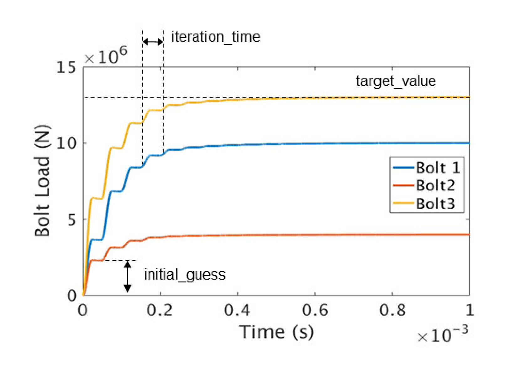
Fig. 10.2 Example of preload iteration.
Subroutine Operation:
The subroutine drives a predictor correct iteration in time. Each predictor corrector cycle is performed over the input deck defined iteration_time. The step cycle is shown in Fig. 10.3 the value of the working variable produced by the subroutine is shown in blue and an example value of the response of the target variable shown in yellow. During the first and second quarter of the cycle the working variable is slowly increased from its old value to the new value. This ramp up is done with a smooth half cycloidal loading ramp. On the first cycle this new value will be half of the initial guess. During the third quarter of the cycle the working variable is held constant. Ideally damping terms will settle the value of the target variable to some relatively constant value during this time. In the fourth quarter of the load cycle the working variable is again held constant and the target variable is evaluated. The evaluation is the time average of the target variable over this fourth of the cycle time. Finally, at the end of the cycle, the new value for the next cycle working variable is defined based on the tangent of the response from the previous to the current iteration. The new working variable value is set such that the error in the target variable versus the target value will be roughly halved. This one half safety factor is used in an attempt to converge the solution monotonically from below. Additionally, regardless of the function tangent computed, the working variable can change by no more than the initial guess each iteration. This is an additional safety factor to prevent overshooting the solution.
It is important to consider that these predictor-corrector iterations only make sense if the target variable reaches a reasonably stable value by the fourth part of each iteration to make a reliable next prediction. For explicit transient dynamics these preload iterations should usually encompass several thousand time steps, but the actual number of steps needed may vary.
The preload solver subroutine will also operate with implicit statics (adagio). One consideration in this case is that each preload iteration cycle will take a minimum of three time steps: a ramp-up step, a hold step, and an evaluation step.
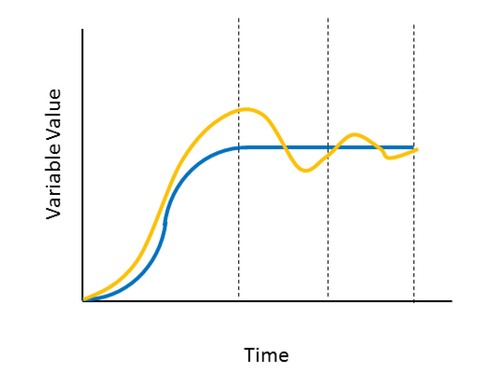
Fig. 10.3 Anatomy of the preload iteration cycle.
State Variables:
The subroutine state variables are used primarily for the internal operation of the subroutine. These variables can be also be post processed to understand how the subroutine is operating. The description of each variable is shown in the below Table Table 10.28. Depending on how the subroutine is used these state variables could be stored in a global variable or there could be a set of state variables at each node or element that is being loaded. The twelfth state variable, which indicates the current error in the preload solution can be particularly useful to look at.
State Number |
Description |
|---|---|
1 |
Start time of current preload iteration |
2 |
End time of current preload iteration |
3 |
Value of working variable at start of current preload iteration |
4 |
Value of working variable at end of current preload iteration |
5 |
Iteration Phase. 1=ramp up (1st and 2nd quarter), 2=hold (3rd quarter), 3=hold/evaluate (4th quarter) |
6 |
Variables 6 and 7 are used to compute a running average of the target variable during the hold/evaluate phase |
7 |
|
8 |
Initial (very first time) value of the working variable |
9 |
Initial (very first time) value of the target variable |
10 |
The time the subroutine was last evaluated |
11 |
The target variable that was computed in the previous preload iteration |
12 |
The relative solution error in target value versus variable error starts at 1.0 and ideally reaches 0.0 |
Usage Guidelines and Warnings:
Pay special care to the USE WITH RESTART and COMPUTE AT EVERY STEP commands present in the example input blocks. The USE WITH RESTART flag ensures the state variables are properly stored in any restart database ensuring the subroutine works correctly with a restart analysis. The COMPUTE AT EVERY STEP command ensures the preload solver correctly updates each an every step. Due to its presence in the USER OUTPUT command block without this command the preload solver would only evaluate at time steps where output is performed, likely yielding strange results in the analysis.
The iteration time must be long enough that the target variable can re-equilibrate to some relatively constant value in time in the target variable evaluation part of the cycle. The subroutine will compare previously found target variable values to current target variable values to make a new prediction for the working variable. If the target variable has a large dynamic oscillation that causes its value to change unrelated to the working variable change this prediction will be poor and the solver will not function correctly.
The analysis must run for enough time that a sufficient number of predictor corrector preload cycles are taken to converge the target variable to the target value. How many cycles are required will depend on how close the initial guess is. However, due to conservative assumptions in the solver usually at least 10 cycles will be required even if the initial guess is good.
This subroutine uses a simple predictor corrector approach and can only solve for conditions where the target versus working variable response is both monotonic and relatively smooth (i.e., at least \(C^0\) continuous).
It is strongly recommended that results be investigated both to ensure an acceptable error bound has been reached and that a reasonable history of the working variable was applied. For example greatly overshooting the target on the initial guess could cause spurious yield which would then be locked into the solution.
A few different combinations of variable types may be used. The working and state variable must be the same type. The target variable must be either a global or the same type as the working and state variables.
10.5.2. aupst_torque_calc
Author: Nathan Crane
Purpose:
This subroutine computes the net torque applied to a body by a set of forces. The torque is defined around an axis defined by two points. The output torque is given as a single value about this axis with a sign following the right hand rule. This subroutine is generally called by a USER OUTPUT command block. For example:
begin user output
  node set = nodelist_1
  compute global ns1 as average of nodal coordinates
end
begin user output
  node set = nodelist_2
  compute global ns2 as average of nodal coordinates
end
begin user variable moment1
  type = global real length = 1
  global operator = sum
end
begin user output
  surface = surface_1    #Contains nodes over which to do
                         # moment summation
  node set subroutine = aupst_torque_calc
  subroutine string parameter: axis_node_1 = ns1
  subroutine string parameter: axis_node_2 = ns2
  subroutine string parameter: force_field = reaction
  subroutine string parameter: output_var = moment1
end
Parameters:
Parameter Name |
Type |
Description |
|---|---|---|
axis_node_1 |
String |
Name of global variable containing location of first axis node |
axis_node_2 |
String |
Name of global variable containing location of second axis node |
force_field |
String |
Name of field containing force values to sum into the torque |
output_var |
String |
Name of output global variable to store the computed moment |
10.5.3. aupst_trans_rot_velocity
Author: Nathan Crane
Purpose:
This subroutine sets an initial velocity on a part that is the combination of an arbitrary rigid body spin rate superimposed on an arbitrary translational velocity. This subroutine is generally called by a INITIAL VELOCITY command block. For example:
begin initial velocity
   block = block_2
   node set subroutine = aupst_trans_rot_velocity
   subroutine real parameter: center_x = 0.0
   subroutine real parameter: center_y = 0.0
   subroutine real parameter: center_z = 2.0

   subroutine real parameter: rot_dir_x = 1.0
   subroutine real parameter: rot_dir_y = 1.0
   subroutine real parameter: rot_dir_z = 1.0

   subroutine real parameter: angular_velocity = 628.31853

   subroutine real parameter: tran_dir_x = 1.0
   subroutine real parameter: tran_dir_y = 1.0
   subroutine real parameter: tran_dir_z = 1.0

   subroutine real parameter: translational_velocity = 173.20508
 end
Parameters:
Parameter Name |
Type |
Description |
|---|---|---|
center_x, center_y, center_z |
Real |
Coordinates of center of rotation |
rot_dir_x, rot_dir_y, rot_dir_z |
Real |
Direction of axis of rotation |
tran_dir_x, tan_dir_y, tan_dir_z |
Real |
Direction of translational velocity |
angular_velocity |
Real |
Spin rate in radians per time |
translational_velocity |
Real |
translational velocity in distance per time |
10.5.4. aupst_cyl_transform
Author: Nathan Crane
Purpose:
This subroutine transforms element stresses from a global rectangular coordinate system to a local cylindrical coordinate system. This subroutine is generally called by a USER OUTPUT command block. For example:
begin user output
  block = block_1
  element block subroutine = aupst_cyl_transform
  subroutine string parameter: origin_point = Point_O
  subroutine string parameter: z_point      = Point_Z
  subroutine string parameter: xz_point     = Point_XZ
  subroutine string parameter: input_stress = memb_stress
  subroutine string parameter: output_stress = cyl_stress
end user output
Requirements:
This subroutine requires a tensor variable to store the cylindrical stress into a variable for each element. The variable is created by the following command block in the Sierra/SM region:
begin user variable cyl_stress
   type = element sym_tensor length = 1
   initial value = 0.0 0.0 0.0 0.0 0.0 0.0
end user variable
Parameters:
Parameter Name |
Usage |
Description |
|---|---|---|
origin_point |
String |
Name of the point at the cylinder origin. |
z_point |
String |
Point on the cylinder axis. |
xz_point |
String |
Point on the line that passes through theta = 0 on the cylinder. |
input_stress |
String |
Name of the Sierra/SM internal input stress tensor variable. |
output_stress |
String |
Name of the Sierra/SM internal output stress tensor variable. |
10.5.5. aupst_rec_transform
Author: Daniel Hammerand
Purpose:
This subroutine transforms element stresses from a global rectangular coordinate system to a different local rectangular coordinate system. This subroutine is generally called by a USER OUTPUT command block. For example:
begin user output
  block = block_1
  element block subroutine = aupst_rec_transform
  subroutine string parameter: origin_point = Point_O
  subroutine string parameter: z_point      = Point_Z
  subroutine string parameter: xz_point     = Point_XZ
  subroutine string parameter: input_stress = memb_stress
  subroutine string parameter: output_stress = new_stress
end user output
Requirements:
This subroutine requires a tensor variable to store the new stress into a variable for each element. The variable is created by the following command block in the Sierra/SM region:
begin user variable new_stress
  type = element sym_tensor length = 1
  initial value = 0.0 0.0 0.0 0.0 0.0 0.0
end user variable
Parameters:
Parameter Name |
Usage |
Description |
|---|---|---|
origin_point |
String |
Name of the point at the cylinder origin. |
z_point |
String |
Point on the cylinder axis. |
xz_point |
String |
Point on the line that passes through theta = 0 on the cylinder. |
input_stress |
String |
Name of the Sierra/SM internal input stress tensor variable. |
output_stress |
String |
Name of the Sierra/SM internal output stress tensor variable. |
10.5.6. copy_data
Author: Jason Hales
Purpose:
This subroutine copies data from one variable to another with offsets given for both variables. This subroutine is generally called by a USER OUTPUT command block. For example:
begin user output
  block = block_1
  element block subroutine = copy_data
  subroutine integer parameter: source_offset = 4
  subroutine string parameter:  source_name = stress
  subroutine integer parameter: destination_offset = 1
  subroutine string parameter:  destination_name = uservarxy
end user output
Requirements:
This subroutine requires that the source and destination fields exist and have lengths at least as great as the values supplied as offsets. The fields used may be defined by the user as variables. In this example, the variable is created by the following command block in the Sierra/SM region:
begin user variable uservarxy
  type = element real length = 1
  initial value = 0.0
end user variable
Parameters:
Parameter Name |
Usage |
Description |
|---|---|---|
source_offset |
Integer |
The offset into the source variable. |
source_name |
String |
The name of the source variable. |
destination_offset |
Integer |
The offset into the destination variable. |
destination_name |
String |
The name of the destination variable. |
10.5.7. trace
Author: Jason Hales
Purpose:
This subroutine computes the trace of a tensor. This subroutine is generally called by a USER OUTPUT command block. For example:
begin user output
  block = block_1
  element block subroutine = trace
  subroutine string parameter:  source_name = log_strain
  subroutine string parameter:  destination_name = uvarbulkstrain
end user output
Requirements:
This subroutine requires that the source and destination fields exist. The source field should have a length of six. The destination field should have a length of one. The destination field will typically be defined by the user as a variable. In this example, the variable is created by the following command block in the Sierra/SM region:
begin user variable uvarbulkstrain
  type = element real length = 1
  initial value = 0.0
end user variable
Parameters:
Parameter Name |
Usage |
Description |
|---|---|---|
source_name |
String |
The name of the source variable. |
destination_name |
String |
The name of the destination variable. |
10.5.8. aupst_cavity_volume
Author: Nathan Crane
Purpose:
Compute the volume of an enclosed side set. This subroutine is generally called by a USER OUTPUT command block. For example:
begin user output
  SURFACE = surface_4000
  SURFACE SUBROUTINE = aupst_cavity_volume
  subroutine string parameter: outputVarName = s4000_vol

  SUBROUTINE REAL PARAMETER: cavitySymmetryPoint_x = 0.0
  SUBROUTINE REAL PARAMETER: cavitySymmetryPoint_y = 0.0
  SUBROUTINE REAL PARAMETER: cavitySymmetryPoint_z = 0.0
  SUBROUTINE REAL PARAMETER: volumeScale           = 2.0

  compute at every step
end
Availability:
Compiled into Adagio 4.24 and later.
Compatible with Presto 2.2 / Adagio 2.2 and later.
Parameters:
Name |
Type |
Description |
|---|---|---|
outputVarName |
String |
Name of global variable in which to store the computed volume. |
cavitySymmetryPoint_x |
Real |
Optional: X coordinate of a point on the intersection of all model symmetry planes. Needed if the cavity is not fully enclosed due to open symmetry planes. |
cavitySymmetryPoint_y |
Real |
Optional: Y coordinate of a point on the intersection of all model symmetry planes. Needed if the cavity is not fully enclosed due to open symmetry planes. |
cavitySymmetryPoint_z |
Real |
Optional: Z coordinate of a point on the intersection of all model symmetry planes. Needed if the cavity is not fully enclosed due to open symmetry planes. |
volumeScale |
Real |
Optional: Value to multiple the final cavity volume by. Defaults to 1.0. May be used to adjust for symmetry boundary conditions. |