7.14. Fluid Pressure
BEGIN FLUID PRESSURE
  #
  # surface set commands
  SURFACE|SIDESET|SIDE SET = <string list>surface_names
  BLOCK = <string list>block_names
  ASSEMBLY = <string list>assembly_names
  INCLUDE ALL BLOCKS
  #
  # specification commands
  DENSITY = <real>fluid_density
  DENSITY FUNCTION = <string>density_function_name
  GRAVITATIONAL CONSTANT = <real>gravitational_acceleration
  FLUID SURFACE NORMAL = <string>direction_name
  DEPTH = <real>fluid_depth
  DEPTH FUNCTION = <string>depth_function_name
  REFERENCE POINT = <string>reference_point_name
  #
  # additional commands
  ACTIVE PERIODS = <string list>period_names
  INACTIVE PERIODS = <string list>period_names
  EXTERNAL FORCE CONTRIBUTION NAME = <string>varName
END [FLUID PRESSURE]
The FLUID PRESSURE command block applies a hydrostatic pressure to each node of each face in the associated surfaces. The pressure at any node is determined from
where \(P\) is the pressure, \(\rho\) is the fluid density at the current time, \(g\) is the gravitational constant, and \(h\) is the current depth of the fluid above the node. The depth of the fluid is computed as the distance from the node up to the current fluid surface in the direction of the fluid surface normal. The global location of the fluid surface is found by adding the current depth to the projection of a datum point along the direction defined in the FLUID SURFACE NORMAL command. The datum point is either the point specified in the REFERENCE POINT line command, or, in the absence of this command, the minimum point on the applied pressure surface in the direction defined in the FLUID SURFACE NORMAL command. Once the current location of the fluid surface is computed, the depth at each node on the pressure surface is computed as the distance from the node to the fluid surface in the direction of the fluid surface normal. See Fig. 7.7.
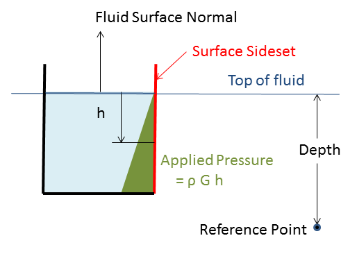
Fig. 7.7 Fluid pressure setup.
Currently, the FLUID PRESSURE command block can be used for surfaces that have faces derived from solid elements (eight-node hexahedra, four-node tetrahedra, eight-node tetrahedra, etc.), membranes, and shells.
The FLUID PRESSURE command block contains three groups of commands—surface set, specification, and additional optional commands.
7.14.1. Surface Set Commands
The surface set commands portion of the FLUID PRESSURE command block defines a set of surfaces associated with the pressure field. The surface specification commands work the same as for the basic pressure boundary condition as described in section Section 7.7.1.1. Similarly, assemblies may contain blocks, surfaces, or assemblies of these.
The force computed from the hydrostatic pressure will be in the opposite direction of the face normal. When using shells or membranes, the analyst must ensure that all face normals composing the pressure application surface are in the correct direction.
7.14.2. Specification Commands
The density and the gravitational acceleration must be input by the user in units consistent with other material properties and the lengths in the mesh. To facilitate convergence of the initial load step, the gradual application of a hydrostatic load may be specified through a time history function for the density. A combination of the DENSITY and the DENSITY FUNCTION sets the value for the fluid density at each time. Either the DENSITY or the DENSITY FUNCTION must be input and both can be used together. If the DENSITY command is input without the DENSITY FUNCTION command, the density will be constant in time at that value. If the DENSITY FUNCTION command is input without a DENSITY command, the function is used as a time history of the density. If both the DENSITY and the DENSITY FUNCTION commands are input, the density value is used as a scale factor on the time history function. Finally, the GRAVITATIONAL CONSTANT sets the value for the acceleration due to gravity, \(g\).
DENSITY = <real>fluid_density
DENSITY FUNCTION = <string>fluid_density_function
GRAVITATIONAL CONSTANT = <real>G
The following command lines are used to define the location of the fluid surface at any time during the analysis:
FLUID SURFACE NORMAL = <string>normal_direction
DEPTH = <real>initial_fluid_depth
DEPTH FUNCTION = <string>depth_function_name
REFERENCE POINT = <string>point_name
The FLUID SURFACE NORMAL command sets the outward normal of the fluid surface. The fluid depth is then assumed to be in the direction opposite this global direction. The DEPTH command is used with the DEPTH FUNCTION command to determine the fluid depth at any time. At least one of these commands must be input. If the DEPTH command is input without the DEPTH FUNCTION command, the fluid depth will be constant in time with that value. If the DEPTH FUNCTION command is input without a DEPTH command, the function is used as a time history of the depth. If both the DEPTH and the DEPTH FUNCTION commands are input, the specified depth is used as a scale factor on the time history function.
The depth and/or depth function are used to determine the current depth, which is added to the appropriate position of a datum point to compute the current location of the fluid surface in the FLUID SURFACE NORMAL direction. Unless the optional REFERENCE POINT command described below is used, the datum point is chosen to be a point on a surface defined in the SURFACE command that minimizes the projection along the FLUID SURFACE NORMAL direction.
The REFERENCE POINT command line specifies the fluid surface relative to an external datum. When applying an external fluid pressure in a quasistatic analysis, a corresponding stiffness due to the external fluid is added to the diagonal terms of the stiffness matrix for the full tangent preconditioner to enhance convergence of the solver.
7.14.3. Additional Commands
These command lines in the FLUID PRESSURE command block provide additional options for the boundary condition:
EXTERNAL FORCE CONTRIBUTION OUTPUT NAME =
  <string>variable_name
ACTIVE PERIODS = <string list>period_names
INACTIVE PERIODS = <string list>period_names
If the EXTERNAL FORCE CONTRIBUTION OUTPUT NAME command line appears there will be a variable created with whatever name the user specifies for variable_name. The variable defines a three-dimensional vector at each node associated with this particular command block. The three-dimensional vector at each node represents the external force due solely to just this particular external force boundary contribution.
Once this variable for the external force contribution is specified, it may be used like any other nodal variable. The user can, for example, specify the variable as a nodal variable to be output in a RESULTS OUTPUT command block. Or the user can reference the variable in a user subroutine.
By default, the FLUID PRESSURE boundary condition will be active throughout an analysis. However, use of the ACTIVE PERIODS and INACTIVE PERIODS commands can be used to limit the action of the boundary condition to specific time periods. The ACTIVE PERIODS command line specifies when the boundary condition is active implying that it is inactive during any periods not included on the command line. Alternatively, the INACTIVE PERIODS determines when the boundary condition will not be active. See Section 2.6 for more information about these commands.