6.5. Element Death
BEGIN ELEMENT DEATH <string>death_name
  #
  # block set commands
  BLOCK = <string list>block_names
  ASSEMBLY = <string list>assembly_names
  INCLUDE ALL BLOCKS
  INCLUDE BLOCKS WITH MATERIAL =
           <string list>material_names
  REMOVE BLOCK = <string list>block_names
  #
  # criterion commands
  CRITERION IS AVG|MAX|MIN NODAL VALUE OF
    <string>var_name <|<=|=|>=|> <real>tolerance
  CRITERION IS ELEMENT VALUE OF
    <string>var_name <|<=|=|>=|> <real>tolerance [KILL WHEN
    <integer>num_intg INTEGRATION POINTS REMAIN]
  CRITERION IS GLOBAL VALUE OF
    <string>var_name <|<=|=|>=|> <real>tolerance
  CRITERION IS ALWAYS TRUE
  MATERIAL CRITERION = ON|OFF(OFF) [KILL WHEN
    <integer>num_intg INTEGRATION POINTS REMAIN]
  #
  # subroutine commands
  ELEMENT BLOCK SUBROUTINE = <string>subroutine_name
  SUBROUTINE DEBUGGING OFF | SUBROUTINE DEBUGGING ON
  SUBROUTINE REAL PARAMETER: <string>param_name
    = <real>param_value
  SUBROUTINE INTEGER PARAMETER: <string>param_name
    = <integer>param_value
  SUBROUTINE STRING PARAMETER: <string>param_name
    = <string>param_value
  #
  # evaluation commands
  CHECK STEP INTERVAL = <integer>num_steps
  CHECK TIME INTERVAL = <real>delta_t
  DEATH START TIME = <real>time
  #
  # miscellaneous option commands
  SUMMARY OUTPUT STEP INTERVAL = <integer>output_step_interval
  SUMMARY OUTPUT TIME INTERVAL = <real>output_time_interval
  DEATH ON INVERSION = OFF|ON(OFF)
  DEATH ON ILL DEFINED CONTACT = OFF|ON(OFF)
  DEATH STEPS = <integer>death_steps(1)
  AGGRESSIVE CONTACT CLEANUP = <string>OFF|ON(OFF)
  DEATH METHOD = <string>DEACTIVATE ELEMENT|DEACTIVATE NODAL MPCS|
      DISCONNECT ELEMENT|(DEACTIVATE ELEMENT)
  LOGFILE OUTPUT = FULL|SOME|MINIMAL(SOME)
  #
  # death on proximity commands
  BEGIN DEATH PROXIMITY
    BLOCK = <string list>block_names
    NODE SET|NODESET = <string list>nodelist_names
    SURFACE = <string list>surface_names
    ASSEMBLY = <string list>assembly_names
    REMOVE BLOCK = <string list>block_names
    REMOVE NODE SET = <string list>nodelist_names
    REMOVE SURFACE = <string list>surface_names
    TOLERANCE = <real>search_tolerance
  END [DEATH PROXIMITY]
  #
  # particle conversion commands
  BEGIN PARTICLE CONVERSION
    PARTICLE SECTION = <string>section_name
    NEW MATERIAL = <string>material_name
      MODEL NAME = <string>model_name
    TRANSFER = <string>NONE|ALL(ALL)
    MAX NUM PARTICLES = <integer>num(1)
    MIN PARTICLE CONVERSION VOLUME = <real>vol
  END [PARTICLE CONVERSION]
  ACTIVE PERIODS = <string list>period_names
  INACTIVE PERIODS = <string list>period_names
  REMOVE OVERLAP AFTER DEATH = ON|OFF (ON)
  #
  # cohesive zone setup commands
  COHESIVE SECTION = <string>sect_name
  COHESIVE MATERIAL = <string>mat_name
  COHESIVE MODEL = <string>model_name
  COHESIVE ZONE INITIALIZATION METHOD = <string>NONE|
    ELEMENT STRESS AVG(NONE)
  ALWAYS EVALUATE ALL CRITERION = OFF|ON(OFF)
END [ELEMENT DEATH <string>death_name]
UPDATE MASS AFTER ELEMENT DEATH  = OFF|ON(ON)
<string>var_name <|<=|=|>=|> <real>tolerance
CRITERION IS ELEMENT VALUE OF
<string>var_name <|<=|=|>=|> <real>tolerance [KILL WHEN
<integer>num_intg INTEGRATION POINTS REMAIN]
CRITERION IS GLOBAL VALUE OF
<string>var_name <|<=|=|>=|> <real>tolerance
CRITERION IS ALWAYS TRUE
MATERIAL CRITERION = ON|OFF(OFF) [KILL WHEN
<integer>num_intg INTEGRATION POINTS REMAIN]
#
# subroutine commands
ELEMENT BLOCK SUBROUTINE = <string>subroutine_name
SUBROUTINE DEBUGGING OFF | SUBROUTINE DEBUGGING ON
SUBROUTINE REAL PARAMETER: <string>param_name
= <real>param_value
SUBROUTINE INTEGER PARAMETER: <string>param_name
= <integer>param_value
SUBROUTINE STRING PARAMETER: <string>param_name
= <string>param_value
#
# evaluation commands
CHECK STEP INTERVAL = <integer>num_steps
CHECK TIME INTERVAL = <real>delta_t
DEATH START TIME = <real>time
#
# miscellaneous option commands
SUMMARY OUTPUT STEP INTERVAL = <integer>output_step_interval
SUMMARY OUTPUT TIME INTERVAL = <real>output_time_interval
DEATH ON INVERSION = OFF|ON(OFF)
DEATH ON ILL DEFINED CONTACT = OFF|ON(OFF)
DEATH STEPS = <integer>death_steps(1)
AGGRESSIVE CONTACT CLEANUP = <string>OFF|ON(OFF)
DEATH METHOD = <string>DEACTIVATE ELEMENT|DEACTIVATE NODAL MPCS|
DISCONNECT ELEMENT|(DEACTIVATE ELEMENT)
LOGFILE OUTPUT = FULL|SOME|MINIMAL(SOME)
#
# death on proximity commands
BEGIN DEATH PROXIMITY
BLOCK = <string list>block_names
NODE SET|NODESET = <string list>nodelist_names
SURFACE = <string list>surface_names
ASSEMBLY = <string list>assembly_names
REMOVE BLOCK = <string list>block_names
REMOVE NODE SET = <string list>nodelist_names
REMOVE SURFACE = <string list>surface_names
TOLERANCE = <real>search_tolerance
END [DEATH PROXIMITY]
#
# particle conversion commands
BEGIN PARTICLE CONVERSION
PARTICLE SECTION = <string>section_name
NEW MATERIAL = <string>material_name
MODEL NAME = <string>model_name
TRANSFER = <string>NONE|ALL(ALL)
MAX NUM PARTICLES = <integer>num(1)
MIN PARTICLE CONVERSION VOLUME = <real>vol
END [PARTICLE CONVERSION]
ACTIVE PERIODS = <string list>period_names
INACTIVE PERIODS = <string list>period_names
REMOVE OVERLAP AFTER DEATH = ON|OFF (ON)
#
# cohesive zone setup commands
COHESIVE SECTION = <string>sect_name
COHESIVE MATERIAL = <string>mat_name
COHESIVE MODEL = <string>model_name
COHESIVE ZONE INITIALIZATION METHOD = <string>NONE|
ELEMENT STRESS AVG(NONE)
ALWAYS EVALUATE ALL CRITERION = OFF|ON(OFF)
END [ELEMENT DEATH <string>death_name]
UPDATE MASS AFTER ELEMENT DEATH = OFF|ON(ON)
The ELEMENT DEATH command block is used to remove elements from an analysis. For example, the command block can be used to remove elements that have fractured, that are no longer important to the analysis results, or that are nearing inversion (explicit only). This command block is located within the region scope. The name of the command block, death_name, is user-defined and can be referenced in other commands to update boundary or contact conditions based on the death of elements creating new exposed surfaces.
Any element in an element block or element blocks selected in the ELEMENT DEATH command block is removed (killed) when one of the criteria specified in the ELEMENT DEATH command block is satisfied by that element. When an element dies, it is removed permanently. Any number of ELEMENT DEATH command blocks may exist within a region.
When an element is killed, the contribution of that element’s mass to the attached nodal mass is removed from the attached nodes. If all the elements attached to a node are killed, the mass for the node and all associated nodal quantities will be set to zero. This updating of mass can be bypassed by using the command UPDATE MASS AFTER ELEMENT DEATH = OFF at the region level, but caution that it must be applied for all element death blocks, and it must be repeated after every restart or transfer to avoid large jumps in mass.
In implicit calculations, elements may be killed based off all available criterion and used in conjunction with control failure in a multilevel solver block. However, material criterion is the only criterion that is truly integrated with the control failure to control the failure progression. Control failure is described in Section 4.7.
In explicit calculations, elements may be killed based on any internal variable, derived variable, material state variable, or user defined variable. Note that user-defined variables for triggering element death should be used with care. There are timing and parallel issues regarding the use of a user-defined variable with element death. User subroutines may work for element death in some situations where one might want to reference a user variable.
![]() The quantity used in an element death criterion statement should have only a single value at each integration point. For example,
The quantity used in an element death criterion statement should have only a single value at each integration point. For example,
criterion is element value of stress(xx) > 10.0
is unambiguous and valid. However,
criterion is element value of stress > 10.0
is ambiguous, and will result in an error. Stress is a \(3 \times 3\) tensor and there is no rational way to compare that tensor to the scalar value 10. If a variable is defined on multiple integration points, the criterion will be triggered if the value is exceeded at any of the integration points. If the command
criterion is element value of stress(xx,:) > 10.0
were used with shells with five integration points, the shells would be killed if the value of stress(xx) at any of the five integration points exceeded 10.
The ELEMENT DEATH command block contains five groups of commands—block set, criteria, evaluation, miscellaneous, and cohesive zone setup. The command block must contain commands from the block set and criteria groups. Command lines from the evaluation and miscellaneous groups are optional, as are the cohesive zone commands.
Following are descriptions of the different command groups, an example of using the ELEMENT DEATH command block, and some concluding remarks related to element death visualization.
6.5.1. Block Set Commands
BLOCK = <string list>block_names
ASSEMBLY = <string list>assembly_names
INCLUDE ALL BLOCKS
INCLUDE BLOCKS WITH MATERIAL = <string list>material_names
REMOVE BLOCK = <string list>block_names
The block set commands portion of the ELEMENT DEATH command block defines a set of blocks for selecting the elements to be referenced. These command lines, taken collectively, constitute a set of Boolean operators for constructing a set of blocks, as described in Section 7.1.1.
Element death must apply to a group of elements. There are four commands for selecting the elements to be referenced: BLOCK, ASSEMBLY, INCLUDE ALL BLOCKS, and INCLUDE BLOCKS WITH MATERIAL. In the BLOCK command line, the user may list a series of blocks through the string list block_names. This command line may also be repeated multiple times. The ASSEMBLY command line lets the user list a series of assemblies of blocks as a list of strings. The INCLUDE ALL BLOCKS command line adds all the element blocks present in the region to the current element death definition. The INCLUDE BLOCKS WITH MATERIAL command line adds all the element blocks that use the specified materials to the current element death definition. There must be at least one BLOCK, ASSEMBLY, INCLUDE ALL BLOCKS, or INCLUDE BLOCKS WITH MATERIAL command line in the ELEMENT DEATH command block.
The REMOVE BLOCK command line allows the user to delete blocks from the set specified in the BLOCK, ASSEMBLY, and/or INCLUDE ALL BLOCKS command line(s) through the string list block_names. The REMOVE BLOCK command line is typically used with the INCLUDE ALL BLOCKS command line. To include all but a few of the element blocks, a combination of the REMOVE BLOCK command line and INCLUDE ALL BLOCKS command line should minimize input information.
6.5.2. Criterion Commands
Any combination of death criteria (CRITERION IS NODAL, CRITERION IS ELEMENT, CRITERION IS GLOBAL, CRITERION IS ALWAYS TRUE, ELEMENT BLOCK SUBROUTINE, MATERIAL CRITERION as appropriate in explicit or implicit) can be specified within a single ELEMENT DEATH command block. However, only one user subroutine criterion (available for explicit only) may appear in a set of criteria command lines. If multiple death criteria are specified for a given element, it will be killed when the first of those criteria is met. In other words, element death with multiple criteria is an OR condition rather than an AND condition.
An explicit dynamics simulation with a material that has both a tension cutoff and a compression cutoff is an example for which element death with multiple criteria would be used – one criterion to set failure in tension and another criterion to set failure in compression. If either the tension cutoff value, as set by the tension criterion, or the compression cutoff value, as set by the compression criterion, was exceeded for an element, the element would be killed.
As a second explicit dynamics example, consider a problem using a nodal criterion and a user subroutine criterion. For this second example, the user is precluded from using a second subroutine criterion because one already exists. A combination of nodal, element, global, or material criteria could be added to the existing nodal and subroutine criteria, but another subroutine criterion could not be added.
![]()
6.5.2.1. Nodal Variable Death Criterion
CRITERION IS {AVG|MAX|MIN} NODAL VALUE OF
  <string>var_name <|<=|=|>=|> <real>tolerance
Any nodal variable may be used by an element death criterion. The input parameters are described as follows:
Nodal variables are present on the nodes of an element, and these nodal values must be reduced to a single element value for use by the criterion. The available types of reduction are
AVG, which takes the average of the nodal values;MAX, which takes the maximum of the nodal values; andMIN, which takes the minimum of the nodal values.The string
var_namegives the name of the variable. See Section 9.12 for a listing of the variables. Parenthesis syntax may be used in the variable name for selection specific variable components or integration points, see Section 9.1.The specified variable, with an optional component specification if the variable has components, may be compared to a given tolerance with one of five operators. The operator is specified with the appropriate symbol for less than (\(<\)) less than or equal to (\(<=\)), equal to (\(=\)), greater than or equal to (\(>=\)), or greater than (\(>\)) The given tolerance is specified with the real value
tolerance.
![]()
6.5.2.2. Element Variable Death Criterion
CRITERION IS ELEMENT VALUE OF
  <string>var_name[(<integer>component_num)]
  <|<=|=|>=|> <real>tolerance |
  <string>derived_quantity[(<integer>int_num)]
  <|<=|=|>=|> <real>tolerance [KILL WHEN <integer>num_intg
  INTEGRATION POINTS REMAIN]
Any element variable may be used by an element death criterion. An element variable is present on the element itself, so no reduction is required, which is why the first line in the format of the above command line differs from that of the nodal criterion command line in Section 6.5.2.1.
For a criterion using an element variable, the variable name, component or integration point number, and tolerance can be specified in the same manner as defined for the nodal criterion command line.
Element state variables can also be used as criteria for element death. The syntax used to specify the variable name differs if a specific integration point is desired.
For LAMÉ solid material models, the variable name is called out directly by name.
For shell material models, the variable name is called out directly by name. By default the element will be killed if the criteria is met at any integration point. Parenthesis syntax (See Section 9.1) may be used to kill based on the state of a specified integration point. For example:
criterion = element value of crack_opening_strain(2) > 0.01
would use the value of the state variable
crack_opening_strainat the second shell integration point through the shell thickness as the criterion for element death.
Refer to Section 9.12.2 for tables with listings of state variables for the various material models.
Derived quantities can also be used for element death. For example the following command:
criterion = element value of von_mises > 1.0e+05
will cause elements to be killed any of the integration points reach a critical value of von_mises. Alternatively, the command:
criterion = element value of von_mises(3) > 1.0e+05
is used to kill an element if a specific integration point reaches the critical value of von_mises.
For elements with multiple integration points, if an element criterion is used with an integration point variable, the integration points are killed individually as the criterion is exceeded on each integration point. The integration points are killed by linearly tapering down all components of the stress over the specified number of death steps. See Section 6.5.6.4 for more information on death steps.
The optional KILL WHEN num_intg INTEGRATION POINTS REMAIN portion of the command line is used to kill the entire element when enough integration points have been killed. This occurs when the number of remaining points drops down to the specified num_intg. For example, for shells with five integration points, the following command:
criterion is element value of stress(xx,:) > 10.0 kill when 2 integration points remain
will check the xx component of stress at each integration point. When the first three integration points reach that criterion, their stresses are linearly tapered down to zero over the specified number of death steps. Once the contributions from each of those three integration points have completely decayed to zero, leaving two remaining integration points, the element is killed. By default the element itself is killed after the first integration point dies.
![]()
6.5.3. Global Death Criterion
CRITERION IS GLOBAL VALUE OF
<string>var_name[(<integer>component_num)]
<|<=|=|>=|> <real>tolerance
Any global variable may be used in an element death criterion. Once the global criterion is reached, all elements specified in the ELEMENT DEATH command block are killed. The variable name, component number, and tolerance can be specified in the same manner as defined for the nodal or element criterion command line.
The input parameters are described as follows:
The string
var_namegives the name of the global variable. See Section 9.12 for a listing of the global variables.Parenthesis syntax may be used in the variable name to specify specific components of the variable. See Section 9.1 for more information.
The specified variable, with an optional component specification if the variable has components, may be compared to a given tolerance with one of five comparison operators as follows:
less than (
<),less than or equal to (
<=),equal to (
=),greater than or equal to (
>=), orgreater than (
>).
The given tolerance is specified with the real value
tolerance.
![]()
6.5.4. Always Death Criterion
CRITERION IS ALWAYS TRUE
This command forces the criterion that determines whether to kill elements specified in the current death block to always be true. In other words, it causes all of those elements to immediately be killed. This command can be used to instantaneously kill a set of elements or convert that set of elements to particles. Converting a set of elements to particles in this manner at the beginning of an analysis can be an alternative to generating a mesh with particle elements.
This command is often used together with the DEATH START TIME command (see Section 6.5.5) to cause a set of elements to be killed or converted to particles at a certain time. This can be used as an alternative to block deactivation using the ACTIVE FOR PROCEDURE command (see Section 6.1.7.9).
6.5.4.1. Material Death Criterion
MATERIAL CRITERION = ON|OFF(OFF) [KILL WHEN
  <integer>num_intg INTEGRATION POINTS REMAIN]
Some material models have a failure criterion. When this material failure criterion is satisfied within an element the material models reduce the stress in these fractured or disintegrated elements to zero. The MATERIAL CRITERION command line can be used to link the decay of stress to zero with deletion of the element from an analysis. Removal of the fractured elements can speed computations, enhance visualization, and prevent spurious inversion of these elements that may stop the analysis.
The material models that currently support the use of the MATERIAL CRITERION command line are:
ELASTIC_FRACTURE(Solid only, see Section 5.2.4)
DUCTILE_FRACTURE(Solid only, see Section 5.2.7)
ML_EP_FAIL(Solid and Shell, see Section 5.2.9)
PLANE_STRESS_RATE_PLASTICITY(Shell only, see Section 5.2.29)
These material models compute the element variables “failure_flag”, “failure_decay”, and “failure_measure.” In its normal computations the “failure_flag” will have a value of 0.0. When the material is decaying the “failure_flag” will have a value of 3.0 and when it is finished decaying the “failure_flag” will have a value of 4.0. As the material is decaying the “failure_decay” will reduce from 1.0 to 0.0. The “failure_measure” value and function is explained in the Control Failure Section 4.7.
Element death will kill an element based on a material criterion when the material model has set the “failure_flag” to 4.0. For a single integration point element, this occurs when the one integration point in the element reaches a “failure_flag” = 4.0. For elements with multiple integration points, the default behavior is for the element to be killed when more than half of the integration points has failed. This behavior is the default because for multi-integration point elements, particularly shells, if there is only a single integration point left, the element is severely under-integrated. The final integration point will generally not attract more load and will never fail. This default behavior can be changed by using the optional KILL WHEN num_intg INTEGRATION POINTS REMAIN command. In this command, num_intg specifies the number of remaining integration points when the element is to be killed.
Consider an element block named part1_ss304 that references a material named SS304. This material, SS304, uses the DUCTILE_FRACTURE material model (see Section 5.2.7). Consider a second element block named ring5_al6061 that references a material named al6061. This material uses the ML_EP_FAIL material model (see Section 5.2.9). An ELEMENT DEATH command block with the command lines
BLOCK = part1_ss304 ring5_al6061
MATERIAL CRITERION = ON
would signal any element in part1_ss304 that fails according to the material model DUCTILE_FRACTURE (in material SS304) and any element in ring5_al6061 that fails according to the material model ML_EP_FAIL (in material al6061) to be killed by element death.
![]()
6.5.4.2. Subroutine Death Criterion
ELEMENT BLOCK SUBROUTINE = <string>subroutine_name
SUBROUTINE DEBUGGING OFF | SUBROUTINE DEBUGGING ON
SUBROUTINE REAL PARAMETER: <string>param_name
  = <real>param_value
SUBROUTINE INTEGER PARAMETER: <string>param_name
  = <integer>param_value
SUBROUTINE STRING PARAMETER: <string>param_name
  = <string>param_value
A death criterion can be specified via a user-defined subroutine (see Section 10), which is invoked by the ELEMENT BLOCK SUBROUTINE command line. The string subroutine_name is the name of a FORTRAN subroutine that is written by the user. The user-defined subroutine for element death must be an element subroutine signature (see Section 10.2.2). The element subroutine will return an output values array and a flag array of one flag per element (see Table Table 10.2 in Section 10). The output values array is ignored. Death is determined by the flag return value. For user-defined subroutines, a flag return value of –1 indicates that the element should die. A flag return value greater than or equal to 0 indicates that the element should remain alive.
Following the ELEMENT BLOCK SUBROUTINE command line are other command lines that may be used to implement the user subroutine option. These command lines are described in Section 10.2.2 and consist of SUBROUTINE DEBUGGING OFF, SUBROUTINE DEBUGGING ON, SUBROUTINE REAL PARAMETER, SUBROUTINE INTEGER PARAMETER, and SUBROUTINE STRING PARAMETER. Examples of using these command lines are provided throughout Section 10.
6.5.5. Evaluation Commands
CHECK STEP INTERVAL = <integer>num_steps
CHECK TIME INTERVAL = <real>delta_t
DEATH START TIME = <real>time
Evaluation of element death criteria may be time consuming. Additionally, reconstruction of contact or other boundary conditions after element death can be time consuming. For these reasons, three command lines are available for determining the frequency at which element death is evaluated. The default is to evaluate element death at every time step. The number of times at which element death evaluation is done may be limited using the following commands.
The
CHECK STEP INTERVALcommand line instructs element death to evaluate the element death criteria only everynum_stepstime steps.The
CHECK TIME INTERVALcommand line instructs element death to evaluate the element death criteria only everydelta_ttime units.The
DEATH START TIMEcommand line instructs element death not to evaluate death criteria before a user-specified time, as given by the real valuetime.
Both the CHECK STEP INTERVAL and CHECK TIME INTERVAL command lines may be used in a command block. Evaluations for element death will be made at both the time and step intervals if both of these command lines are included.
All three of CHECK STEP INTERVAL, CHECK TIME INTERVAL, and DEATH START TIME are optional command lines.
6.5.6. Miscellaneous Commands
The command lines listed below need not be present in the ELEMENT DEATH command block unless the conditions addressed by each call for their inclusion.
6.5.6.1. Summary Output Commands
At the end of a run, a summary of all element death blocks is output to the log file. The SUMMARY OUTPUT STEP INTERVAL or SUMMARY OUTPUT STEP INTERVAL commands can be used to request that the summary be output to the log file at regular intervals during the run. The SUMMARY OUTPUT TIME INTERVAL command results in the summary being printed every output_step_interval steps, while the SUMMARY OUTPUT TIME INTERVAL results in the summary being printed once every output_time_interval time units. These two commands can be supplied individually, together or not at all. If neither are used, the summary is printed only at the end of execution.
This command applies to all element death blocks. If these commands appear in multiple element death blocks, the values specified in the last instance of each of these commands prevails.
![]()
6.5.6.2. Death on Inversion
DEATH ON INVERSION = ON|OFF(OFF)
If the DEATH ON INVERSION command line is set to ON, any element that inverts will be killed. This command currently only works for uniform gradient eight-noded hexahedral elements, four-, eight-, and ten-noded tetrahedral elements, and four-noded shells.
6.5.6.3. Death on Ill-defined Contact
DEATH ON ILL DEFINED CONTACT = ON|OFF(OFF)
If the DEATH ON ILL DEFINED CONTACT command line is set to ON, any element that would create invalid geometry for contact will be killed. This currently only works for uniform gradient eight-noded hexahedral elements and four-noded tetrahedra elements. An example of an element that creates an invalid contact geometry is an element that is partially inverted in such a way that some regions of the element have negative volume and exterior faces of the element point in the wrong directions.
A highly deformed element can have a positive total volume, permitting internal force to still be calculated, but have inverted local regions that make it invalid for contact. For this reason, killing elements due to ill-defined contact can be important to obtain solutions for contact problems in which elements are experiencing large distortions. Using death on inversion alone is not sufficient for those cases.
![]()
6.5.6.4. Death Steps
DEATH STEPS = <integer>death_steps(1)
If the DEATH STEPS command line is used and the value for death_steps is set to a value greater than 1, all components of the stress and the hourglass forces in a killed element are linearly scaled down until they reach 0 over the specified number of steps. Gradually releasing the energy due to killing an element over a number of steps can avoid instabilities that might occur if that element were suddenly killed. If this is done over an excessively large number of steps, however, the killed element may participate in the analysis long after it is relevant, and may cause problems if it undergoes excessive deformation or inverts while its stresses are being tapered off. The default number of steps, as provided in the integer value death_steps, is 1.
The value selected for death_steps will depend on the loads, material models, and model complexity associated with an analysis. A small number (3 to 5) may be sufficient to prevent instabilities for most cases. However, it may be necessary to use a value of 10 or larger.
If an element death criterion is used in an element with multiple integration points, the stresses for the integration points that have exceeded the criterion are decayed individually over the specified number of death steps. When the required number of death steps for an integration point has been exceeded, that integration point no longer contributes to the element internal force, and is considered dead. When the required number of integration points to kill the entire element (based on the user-input KILL WHEN num_intg INTEGRATION POINTS REMAIN – See Section 6.5.2.2) have reached that state, the process of killing the element is initiated, and the stresses in the remaining integration points and the hourglass forces are all scaled down over the specified number of death steps.
If an element reaches a death criteria and while in the process of fading out reaches another death criteria whichever death criteria has the lowest number of remaining steps will be used. For example if a material has a death criteria on stress and fades out of 10 death steps and in the process of that fade out has a bad shape and is killed in a single death step the single death step inversion criteria will overwrite the stress fade out criteria.
See Section 8.4.7 for more information on how contact interacts with element death.
6.5.6.5. Aggressive Contact Cleanup
AGGRESSIVE CONTACT CLEANUP = <string>OFF|ON(OFF)
The AGGRESSIVE CONTACT CLEANUP command line enables the use of element death in an attempt to guarantee a valid contact mesh. Certain complex meshes with extensive element death can be problematic for the contact algorithms on some mesh decompositions. This command allows element death to query the contact algorithm and then remove any elements that the contact algorithm flags as having the potential to cause contact to fail.
6.5.6.6. Death Method
DEATH METHOD = <string>DEACTIVATE ELEMENT|DEACTIVATE NODAL MPCS|
  DISCONNECT ELEMENT|(DEACTIVATE ELEMENT)
The DEATH METHOD command specifies what happens when an element meets the death criterion. The following strings can be used as arguments to this command: DEACTIVATE ELEMENT, DEACTIVATE NODAL MPCS, DISCONNECT ELEMENT. The behavior controlled by these options is described below.
With the default option,
DEACTIVATE ELEMENT, the element is deactivated, effectively removing it from the mesh.The
DEACTIVATE NODAL MPCSoption removes the nodes of a killed element from any multi-point constraints. This only has an effect if the element has nodes that are in multi-point constraints. The multi-point constraint deactivation option can be used to break an element away from the mesh, allowing it to move independently. It can also be used to activate cohesive zones.The
DISCONNECT ELEMENToption disconnects the element from the mesh, allowing the element to move independently. The disconnected element will no longer share any nodes with neighboring elements, and will only interact with the remainder of the mesh through contact.
When using element disconnection, it is necessary to use at least some hourglass stiffness and/or viscosity to prevent large deformations of the disconnected elements in zero energy modes. In addition, it is recommended that a secondary shape-based criterion be used in a separate element death command block to fully remove the disconnected elements if they begin to deform too much. The following example of an additional element death block to be used together with element disconnection shows recommended shape criteria:
begin element death
  include all blocks
  #Kill an element if it has negative volume
  death on inversion = on
  #Kill an element if it has become locally inverted (i.e., concave)
  criterion is element value of nodal_jacobian_ratio <= 0.0
  #Kill an element that is becoming very large (shells only)
  criterion is element value of perimeter_ratio > 10.0
end
6.5.6.7. Logfile Output
The REMOVE OVERLAP AFTER DEATH option removes overlap after element death when using the element disconnection capability. After each time step where elements are disconnected, the overlap removal algorithm runs to help prevent spurious energy from being introduced. This option has no effect for particle conversion.
LOGFILE OUTPUT = FULL|SOME|MINIMAL(SOME)
The LOGFILE OUTPUT command controls the verbosity of log output from element death.
The
FULLoption is the most verbose and detailed setting, which triggers printing of each and every element which is killed in a given time step, including its global identifier, containing block name, and criterion which caused its death. For example,Block: block_1 Killed Element: 901 Death Criterion: \ Death Block: 'dx' : Avg Nodal Value Of: coordinates(x) Block: block_1 Killed Element: 902 Death Criterion: \ Death Block: 'dx' : Avg Nodal Value Of: coordinates(x) Block: block_1 Killed Element: 903 Death Criterion: \ Death Block: 'dx' : Avg Nodal Value Of: coordinates(x) Block: block_1 Killed Element: 904 Death Criterion: \ Death Block: 'dx' : Avg Nodal Value Of: coordinates(x) Block: block_1 Killed Element: 905 Death Criterion: \ Death Block: 'dx' : Avg Nodal Value Of: coordinates(x)
The
SOMEoption is the default setting, which triggers printing of only a summary of the number of elements killed by each criterion in a given timestep. For example,At time: 2.3e-06 100 elements died due to Death Block: 'dx' : \ Avg Nodal Value Of: coordinates(x)
The
MINIMALoption is the least verbose setting, which prints only a global total of the number of elements killed in a given time step, e.g.,*** Killed 200 Elements on time step 22 for a total of 200 dead.
![]()
6.5.6.8. Death on Proximity
BEGIN DEATH PROXIMITY
  BLOCK = <string list>block_names
  NODE SET|NODESET = <string list>nodelist_names
  SURFACE = <string list>surface_names
  ASSEMBLY = <string list>assembly_names
  REMOVE BLOCK = <string list>block_names
  REMOVE NODE SET = <string list>nodelist_names
  REMOVE SURFACE = <string list>surface_names
  TOLERANCE = <real>search_tolerance
END [DEATH PROXIMITY]
Sierra/SM provides the option to kill elements that get within a search tolerance of nodes in a specified mesh entity set. Proximity is measured by the smallest distance from the nodes and element centroids of the elements specified in the BEGIN ELEMENT DEATH command block to the nodes in the mesh entity set defined in the command block BEGIN DEATH PROXIMITY.
The commands BLOCK, NODE SET|NODESET, SURFACE, ASSEMBLY, REMOVE BLOCK, REMOVE NODE SET, and REMOVE SURFACE inside the command block BEGIN DEATH PROXIMITY form the mesh entity set of nodes used to search against for the proximity measure.
The command TOLERANCE specifies the distance tolerance. Once an element’s proximity measure is less than or equal to the distance tolerance the element will be killed.
![]()
6.5.6.9. Particle Conversion
BEGIN PARTICLE CONVERSION
  PARTICLE SECTION = <string>section_name
  NEW MATERIAL = <string>material_name
    MODEL NAME = <string>model_name
  TRANSFER = <string>NONE|ALL(ALL)
  MAX NUM PARTICLES = <integer>num(1)
  MIN PARTICLE CONVERSION VOLUME = <real>vol
END [PARTICLE CONVERSION]
Sierra/SM provides the option to convert elements to particles when they are killed, rather than removing them from the mesh. This option is activated by using the BEGIN PARTICLE CONVERSION command block inside the ELEMENT DEATH command block. Particle conversion can be useful when elements become too highly deformed to be represented by solid elements. This allows for the highly deformed solid elements to be removed from the mesh, while retaining the mass associated with those elements in the form of particles.
The name of a particle section block (defined with a PARTICLE SECTION command block, see Section 6.6) must be provided with the PARTICLE SECTION command line to define the properties of the created particles. Particles may be created that use the SPH or mass particle formulation, as defined by the section.
The material models for the created particles may be optionally prescribed by providing the name and model for a defined material in the NEW MATERIAL command. By default, the particle uses the material model of the solid element from which it has been converted, and all element data that can be retained, including material state variables, are transferred during conversion. This behavior may be modified by specifying the transfer type through the TRANSFER command. If all the applicable element data should be transferred, the ALL option should be specified (this is the default if no transfer type is specified). If the particles should be created with reinitialized state data, the NONE option should be specified. Moreover, if a new material type is specified for conversion, the TRANSFER option will apply, but likely much of the material state data will not be transferable and will be lost as the element is converted to a particle. The best option when using a new material is to also specify a transfer type of NONE.
Warning
It is important that material state data be correctly initialized on SPH particles. It is possible to generate incompatible material states with the command TRANSFER=NONE, or by changing the material type. An incorrect state initialization during conversion may result in errors or in the worst cases, hanging of the analysis.
Particle conversion works with most element geometries including hexahedra, tetrahedra, shells, beams, and other particles. The converted particle is placed at the centroid of the removed element. For shells, beams and particles the new particle is placed inside of the lofted volume that the structural element represents. The mass of the particle equals the mass of the converted element. The velocity and/or temperature of the converted particle is set to the average velocity/temperature of the source element’s nodes. The radius of the converted particle is computed to allow the particle to fit inside the void space left by removal of the solid element. If no particle can fit in that space, no particle is created. This typically occurs when an element has inverted or the center of mass is not on the interior of the element, as seen in Fig. 6.28.
Particle conversion is supported primarily for single integration point elements, with limited support for the 8 integration point selective deviatoric and total Lagrange hexahedral element types. In this case, particle state is transferred by copying the values contained in the first integration point of the parent element.
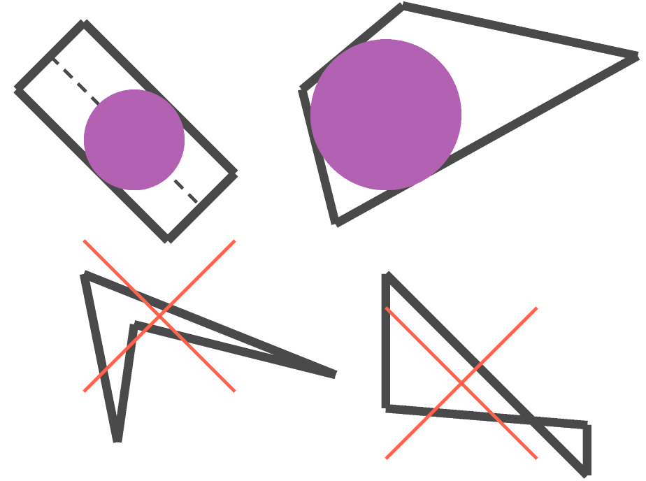
Fig. 6.28 Examples of how an element is converted and when it is not converted.
A single element can optionally be converted into multiple particles. The number of particles to convert to is specified with the MAX NUM PARTICLES command and MIN PARTICLE CONVERSION VOLUME command. The usage of these commands is as follows:
If neither of these command lines is present, one particle is placed at the centroid of the element.
If only the MAX NUM PARTICLES command line is present, the element will be cut into the specified number of roughly equal volume sections. A particle will then be placed at the centroid of each of these sections.
If only the MIN PARTICLE CONVERSION VOLUME command line is present, the element will be subdivided until a number of volumes each of roughly the specified volume is reached. A new particle will then be placed at the centroid of each of these sub-volumes.
If both the MAX NUM PARTICLES and MIN PARTICLE CONVERSION VOLUME commands are specified, the element will be subdivided until either the minimum volume of the sub-parts is reached, or the maximum number of sub-parts is reached. When one of these criteria is reached, a new particle is placed into each created sub-volume.
Warning
When performing element to particle conversion, sometimes it is beneficial to deactivate particles created from element death later on in the analysis. To accomplish this use case, all death blocks involving particle conversion should occur before death blocks deactivating elements. This will allow the particle block to be created at the time the death block is parsed, and thus, it will exist when the “deactivate element” death block is parsed.
6.5.6.10. Active Periods
The following command lines can optionally be used in the ELEMENT DEATH command block:
ACTIVE PERIODS = <string list>period_names
INACTIVE PERIODS = <string list>period_names
These command lines determine when element death is active. See Section 2.6 for more information about these optional command lines.
6.5.7. Cohesive Zone Setup Commands
The commands listed here are all related to activation of cohesive zones by element death.
COHESIVE ZONE INITIALIZATION METHOD = <string>NONE|
  ELEMENT STRESS AVG(NONE)
The COHESIVE ZONE INITIALIZATION METHOD command controls the initialization of cohesive zones that are activated through element death. This command should only be used if there are cohesive zones between elements and all nodes of those elements are initially attached together via multi-point constraints. When element death is used to deactivate the constraints (with the DEATH METHOD = DEACTIVATE NODAL MPCS), the exposed cohesive zone can be given an initial state. The options are to either do nothing (NONE) or to initialize the tractions in the cohesive element based on the stresses in the two elements on either side of the cohesive zone (ELEMENT STRESS AVG). How the cohesive zone uses the initial traction will depend on the cohesive surface material model used.
![]()
6.5.8. Example
The following example provides instructions to kill elements in block_1 when they leave a bounding box. This type of element death can be useful in an analysis where some peripheral parts, because of fracture, separate and fly away from a central body, where this central body is the part of interest. In this case, these peripheral parts no longer impact the solution. The instructions in this ELEMENT DEATH command block will cause the parts to be killed, thus speeding up the computation.
begin element death out_of_bounds
  block = block_1
  # check x coordinates
  criterion is avg nodal value of coordinates(1) >=  10
  criterion is avg nodal value of coordinates(1) <= -10
  # check y coordinates
  criterion is avg nodal value of coordinates(2) >=  10
  criterion is avg nodal value of coordinates(2) <= -10
  # check z coordinates
  criterion is avg nodal value of coordinates(3) >=  10
  criterion is avg nodal value of coordinates(3) <= -10
end element death out_of_bounds
If an assembly, assembly_1, containing block_1 is used, the example would read:
begin element death out_of_bounds
  assembly = assembly_1
  # check x coordinates
  criterion is avg nodal value of coordinates(1) >=  10
  criterion is avg nodal value of coordinates(1) <= -10
  # check y coordinates
  criterion is avg nodal value of coordinates(2) >=  10
  criterion is avg nodal value of coordinates(2) <= -10
  # check z coordinates
  criterion is avg nodal value of coordinates(3) >=  10
  criterion is avg nodal value of coordinates(3) <= -10
end element death out_of_bounds
6.5.9. Element Death Visualization
When an element dies, information about this element will still be sent, along with information for all other elements, to the Exodus II results file. (Section 9 describes the output of element variables to the results file.) The death status of the elements may be output to the results file by requesting element variable output for the element variable DEATH_STATUS. Including the command line
ELEMENT DEATH_STATUS as death_var
in a RESULTS OUTPUT command block (Section 9) will output this element variable with the name death_var in the results file. The convention for DEATH_STATUS is as follows: An element with a value of 1.0 for DEATH_STATUS is a living element. An element with a value of less than or equal to 0.0 for DEATH_STATUS is a dead element.
In the case other than MATERIAL CRITERION, a DEATH_STATUS value between 1.0 and 0.0 indicates an element is in the process of dying. A dying element has its material stress scaled down over a number of time steps. The current scaling factor for an element is given by DEATH_STATUS. Whether an element can have a value other than 0.0 or 1.0 for DEATH_STATUS will depend on whether the DEATH STEPS option has been used in the ELEMENT DEATH command block. If the number of steps over which death occurs is greater than 1, then DEATH_STATUS can be some value between 0.0 and 1.0.
If DEATH_STATUS is written to a results file, it is possible to use DEATH_STATUS to exclude killed elements from any view of the model in visualization software. A subset of the mesh showing only living elements can be created by visualizing only those elements for which DEATH_STATUS > 0.0. The procedure for filtering results in this way varies for different post-processing tools.
In addition to DEATH_STATUS there are DEATH_STATE and STATUS which are element variables used to tell if an element has been killed. DEATH_STATE is set to 0 when the element has not been killed yet or has been killed but not printed to the logfile and 1 when the element has been killed and printed to the logfile. STATUS follows the same pattern with 0 being alive while 1 is killed.
When an analysis is using element death, the log file contains a table of marker values that will be applied to dead elements. The marker values allow determining which elements where killed and by which criterion. The marker variables are stored in the element variable KILLED_BY_CRITERION and are available for output on the mesh results file. Additionally, a global count of how many elements were killed by each criterion is printed at the end of the run log file.