7.2. XFEM for Fracture and Fragmentation
The most common application of XFEM is modeling of fracture, fragmentation, sand failure in structures. Currently supported fracture capabilities are
prescribed, static or stationary cracks,
prescribed cracks with a specified direction and rate of growth,
prescribed cracks which are allowed to propagate by mechanics-based growth criteria, and
cracks which are nucleated and propagated via mechanics-based criteria.
These capabilities are detailed below.
7.2.1. Fixed and Prescribed XFEM Discontinuities
A “fixed” XFEM discontinuity is stationary in both time and space; the failure surface does not change after initialization. A fixed infinite plane discontinuity can be inserted via the ADD INFINITE PLANE command, while a disc-shaped cut with a fixed radius may be inserted via the ADD DISC command. Note that the specified surfaces are used to cut the mesh in the reference configuration.
A “prescribed” XFEM discontinuity is restricted to propagate along a specific path in time. In order to prescribe an XFEM discontinuity, a disc must be inserted via the ADD DISC command. The discontinuity may “grow” by adding a time-varying function at the end of the ADD DISC command or by mechanics growth, described in Section 7.2.2 below.
7.2.2. Spontaneous Crack Nucleation, Growth, and Branching
The current XFEM implementation enables the natural evolution of fractures in materials based on mechanics nucleation, growth, and branching criteria.
7.2.2.1. Crack growth
Growth, or propagation, can be enabled via the following command lines:
MECHANICS GROWTH METHOD = MECHANICS FAILURE
CRITERION = <string>{AVG NODAL|MAX NODAL|
         MIN NODAL|ELEMENT|GLOBAL}
         VALUE OF <string>variable
         {>=|>|=|<|<=} <real>threshold
FAILURE SURFACE EVOLUTION = PLANAR|PIECEWISE LINEAR|
         SINGLE CRACK(PLANAR)
The CRITERION command line specifies the criterion for propagation or growth of the crack from element to element. This command is precisely analogous to element death; refer to the Sierra/SM User Manual for additional details. FAILURE SURFACE EVOLUTION specifies any geometric restrictions on fracture growth:
PLANARis the default option, which restricts the crack to grow only in the plane in which it is initialized, preventing the crack from turning or twisting.PIECEWISE LINEARallows a crack to change directions such that it is planar within a single element; however, this option may lead to a fracture surface which is discontinuous from element to element.
Mechanics growth can be delayed in the analysis by specifying a start time (\(\ge 0\)) in the MECHANICS GROWTH START TIME command.
The way in which the crack growth angle change is computed can be specified via the ANGLE CHANGE command line to smooth or regularize sharply varying stress fields in the neighborhood of crack fronts. Available angle change options are
STRESS EIGENVECTOR, which calculates the growth angle of the crack from the maximum principal stress eigenvector in the element to be cut;ONE RING, which defines the new failure plane by the maximum principal stress eigenvector of the emph{average} stress in the node-connected neighboring elements (or one-ring) of the element to be cut; andLENGTH SCALE, which computes the crack failure plane as the maximum principal stress eigenvector of the average stress in elements within a specified radial distance of the element to be cut. This distance can be specified via theANGLE CHANGE LENGTH SCALE OUTER RADIUScommand. By specifyingANGLE CHANGE LENGTH SCALE INNER RADIUS, in addition to including elements inside a given outer length scale, the growth algorithm will emph{exclude} elements within a given inner radius of the crack front from the direction computation. Because the length scale entails a computation involving, in general, a number of elements surrounding the crack front, this option may incur significant additional simulation time within in each load step.
The variable used to calculate the angle change can be specified via
SOLID GROWTH DIRECTION VARIABLE = ...
SHELL GROWTH DIRECTION VARIABLE = ...
for solid and shell elements, respectively. The default variable used for solid elements is “stress,” while the default variable used for shell elements is “membrane stress.”
7.2.2.2. Crack nucleation
Spontaneous nucleation, or initiation, of cracks may be controlled by the command lines
GENERATION BY NUCLEATION = <string>NO|ELEMENT-BASED(NO)
NUCLEATION CRITERION = ...
Currently, only element-based nucleation is supported, in which a single element is cut if it exceeds the user-defined nucleation criterion (which follows the same form as the growth criterion). Nucleated cracks then grow normally according to the specified mechanics growth criterion.
7.2.2.3. Crack branching
Branching behavior may also be modeled via the commands
CRACK BRANCHING = ALLOWED
BRANCHING CRITERION = ...
Currently, cracks may only branch from a single point on an element edge (i.e., from a virtual node on the element edge created by the first cut). Examples of eligible and ineligible branching locations are illustrated in Fig. 7.3. All presently cut elements are branching candidates. The user-defined failure condition is examined for each element, and if the value exceeds the failure criteria, the stress eigenvectors are calculated and used to determine the possible branching direction.
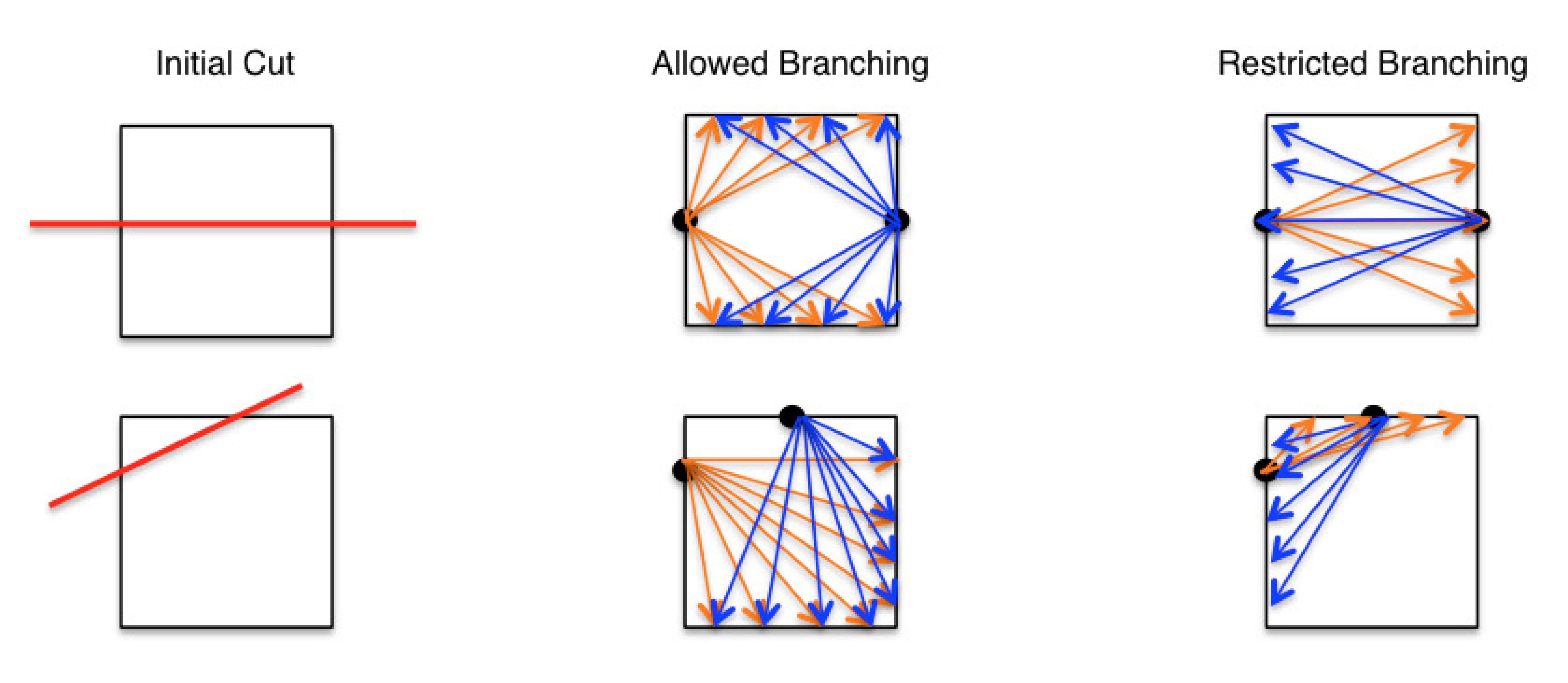
Fig. 7.3 Example of allowed and restricted branching.
7.2.3. Cohesive Zone Insertion
Cohesive zones can be adaptively inserted between the XFEM discontinuities in order to better capture fracture patterns, convergence, and energy dissipation. To insert cohesive zones with XFEM,
a cohesive section must be specified in the XFEM command block via the
COHESIVE SECTIONcommand line,a cohesive material must be specified via the
COHESIVE MATERIALcommand line, anda cohesive model must be specified via the
COHESIVE MODELcommand line.
In order for the cohesive zones to be inserted with the stress initialized to that of the failing element, the INITIAL SURFACE COHESIVE = TRUE option must be used.
Warning
Cohesive zone insertion for tetrahedral elements is not yet supported.
7.2.4. Other Options
Several miscellaneous or experimental XFEM capabilities are available for fracture and fragmentation analysis.
7.2.4.1. Volume Fraction Lower Bound
By default, the XFEM implementation in Sierra does not “clip” or remove elements with arbitrarily small volume fractions. This can create issues with the conditioning of implicit solves.
The VOLUME FRACTION LOWER BOUND command allows the user to specify a threshold. By default, when a lower bound is provided with this command, elements whose volume fractions are below the specified threshold will be removed from the calculation (DELETE). When the RETAIN option is specified, elements whose volume fractions are below this specified threshold will be retained, but have their volume fractions are reset to the lower bound specified by the threshold value. This insures that the smallest volume fraction of any partial element anywhere in the domain will not be smaller than the threshold.
Warning
The VOLUME FRACTION LOWER BOUND can result in the loss of mass conservation for an embedded object, whether in the default mode when these small volume fractions are removed or in the RETAIN mode when mass is added.
7.2.4.2. XFEM damage-based failure
XFEM can also be used to cut the mesh along a specific field on the mesh (such as a phase field damage variable). The name of this variable is specified via the CUT WITH DAMAGE VARIABLE command.
Warning
The CUT WITH DAMAGE VARIABLE option is in-development and not a hardened capability.
7.2.4.3. Identification of separate XFEM fragments
The CALCULATE FRAGMENT IDS command can be used to output both element and nodal fragment ID fields. Turning this option to ON will set both the element variable called element_fragment_id as well as the nodal variable called node_fragment_id at the end of the simulation. Each ID corresponds to a distinct fragment from the XFEM simulation. Elements and nodes within a fragment will all be assigned the same fragment ID. Labeling of the fragment IDs is arbitrary, but the numbering always begins with 1 and goes to the total number of fragments in the simulation. Post-processing scripts can be use in conjunction with these fields to compute quantities such as fragment mass and momentum distributions.