4.3.5. Boundary Conditions
Boundary conditions are needed in order to define a well-posed boundary value problem as described by the FEM equations. These boundary conditions are often denoted as Dirichlet, Neumann, Robin or distinguishing conditions. Dirichlet or essential boundary conditions for a solution field stem directly from the governing equations for a particular physics. In Aria, Neumann and Robin conditions are generally categorized as flux boundary conditions. Distinguishing conditions enforce a boundary i condition via an auxiliary equation, which is discussed in more detail in Disting.
This section documents primarily the native Aria boundary condition, BC, line commands within the current version of the code. Recall from a previous chapter outlining the general FEM that the method gives rise to boundary terms Governing Equations, i.e. various flux boundary conditions. In the command reference, Dirichlet boundary conditions are described as well as the various flux boundary condition types.
Boundary conditions are defined at the Region scope of the input file. See the command reference for a comprehensive list of possible BC options. The general format of a boundary condition line command is as follows:
BC [TYPE] for [QUANTITY] on [PART] = [MODEL] [MODEL ARGS...]
Here the TYPE denotes if the BC is a dirichlet BC, one of the flux BC types, or
disting (distinguishing).
The QUANTITY is defined as follows:
For
BC Dirichlet, the quantity is theDOFfield on which the BC is applied. ThisDOFOtherwise, the quantity is the
EQUATIONcontributed to by the flux or distinguishing condition.
In either case, the equation/DOF must be declared with an EQ line at either Aria Region
or Equation System scope (see
Equation Specification). Note that material
phase, species, or LS phase can be specified in the DOF/EQUATION argument e.g.
# Dirichlet BC for gas phase energy equation
BC flux for energy in gas_phase on block_1 = ...

# Dirichlet BC for Li+ in liquid phase
BC dirichlet for species of Li+ in liquid_phase on block_1 = ...

# Distinguishing BC for no slip mesh motion, with zero "leak" velocity
BC Disting for Mesh_x on surface_2 = Kinematic v0=0
See General Naming Convention for more information.
Boundary conditions can also be specified as string functions (see String Functions), which provides a mechanism for user customization. For example, a user can define a distinguishing condition that is only active in regions above a certain temperature, t_ref, and otherwise does not alter the solution as
BC Disting for Species on surface_2 = Scalar_String_Function
  F = "(temperature - t_ref) > 0.0 ? (species - 100) : 0.0"
The PART corresponds to a mesh entity, and can include both single parts
(e.g. block_1) as well as assemblies or mesh groups (see
Assemblies and Mesh Groups).
Finally the MODEL defines how the source term is calculated. Note that
multiple source lines may be defined for a given DOF / PART.
For example, a dirichlet BC on temperature and flux BC for the energy equation can be defined as follows
# Scope: Sierra > Procedure > Aria Region
BC dirichlet for temperature on surface_1 = constant value = 300 # K
BC flux for energy on surface_2 = constant flux = 1.0
4.3.5.1. Periodic BCs
Aria provides a periodic boundary condition capability. Two flavors of periodicity are supported, standard periodicity for surfaces separated by fixed distance and cyclic periodicity for surfaces separated through a fixed rotation angle as illustrated in Fig. 4.7. The underlying implementation is based upon augmenting the basic governing equations with multi-point constraints on nodal DOF at the periodic boundaries and is equally applicable to scalar and vector DOF. The enforcement employs nodal DOF, hence the capability is limited to grids with conforming surface nodes, i.e. the mesh is periodic as well. Note that for non-conforming surface topologies, periodic contact can be used instead.
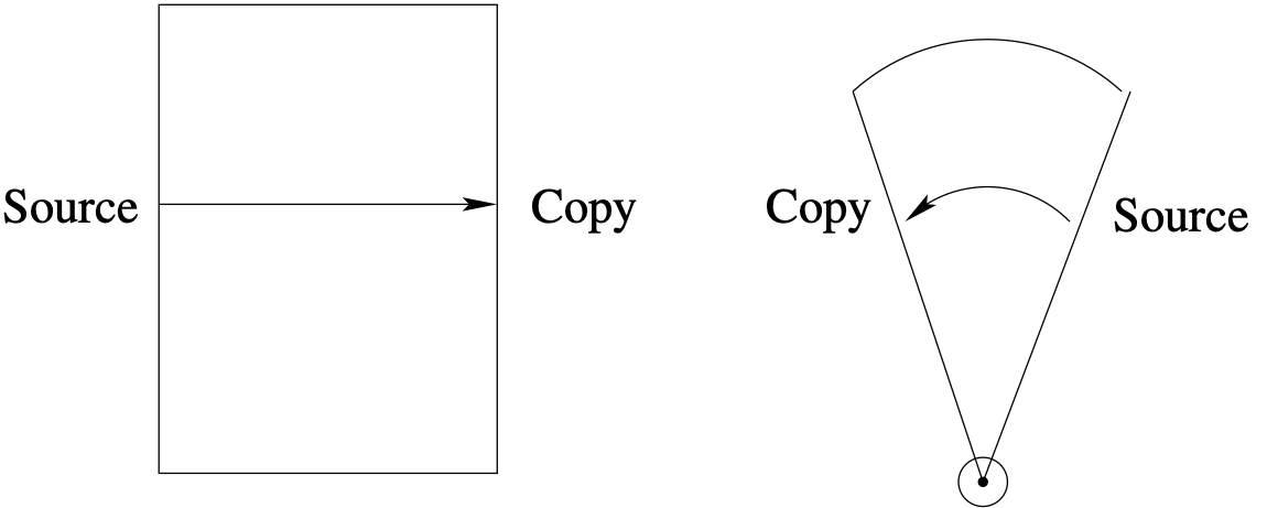
Fig. 4.7 Standard and Cyclic Periodicity
Internally, a search procedure is used in order to define node constraint pairs. Since a meshed discretization is subject to intrinsic error in the nodal coordinates, an acceptable tolerance specification is used to insure that pairings are appropriately defined. Note that application of large tolerances may lead to incorrectly defined pairings.
See the command reference for more details on specifying periodic BCs. Note that cyclic periodicity requires that the user specify both Reference Axis of rotation and Point on Axis (a point on the reference axis) in the Periodic command block. Here Reference Axis and Point on Axis are associated with Define Direction and Define Point respectively. These two additional quantities are usually defined at the Domain scope (outside of the Procedure).
4.3.5.2. Coupling BCs for Organic Material Decomposition
Aria provides the capability of coupling between porous (see Organic Material Decomposition (OMD)) and fluid blocks using flux-style boundary conditions. The boundary conditions described here are for a single region computation; for the most part, these boundary conditions can be used for a multi-region computation with the phrase ‘one_region’ omitted. These boundary conditions are imposed as Robin boundary conditions,

where  is the flux into the porous region and
  is the flux into the
fluid region. The boundary conditions for the pressure mass balance equation on
the porous side and the corresponding flux condition on the fluid side CVFEM
continuity equation are written as
(see Fluid_Robin_Coupled_One_Region
and Porous_Robin_One_Region
for syntax specific details)
is the flux into the
fluid region. The boundary conditions for the pressure mass balance equation on
the porous side and the corresponding flux condition on the fluid side CVFEM
continuity equation are written as
(see Fluid_Robin_Coupled_One_Region
and Porous_Robin_One_Region
for syntax specific details)
BC flux for mass_balance in gas_phase on surface = fluid_robin_coupled_one_region
BC flux for cvfem_continuity on surface = porous_robin_one_region
This boundary condition uses a penalty coefficient of the form

where  is the mesh width adjacent to the interface (need to check what
happens with a non-uniform mesh). The default value of
is the mesh width adjacent to the interface (need to check what
happens with a non-uniform mesh). The default value of  is 0.001.
If this parameter is too large, the increase in pressure might be
underpredicted.
is 0.001.
If this parameter is too large, the increase in pressure might be
underpredicted.
A distinguishing boundary condition is used on the fluid momentum equation,
(4.1)
where  is the imposed normal component of velocity and
  is
the imposed tangential component of velocity. The normal component is computed
directly from the continuity flux at the interface,
is
the imposed tangential component of velocity. The normal component is computed
directly from the continuity flux at the interface,
(4.2)
The tangential component is based on a variation of the classical Beavers-Joseph-Saffman condition [32, 33] for the slip velocity which has been extended to non-planar surfaces in multidimensional flow [34], which defines a provisional model velocity
(4.3)
where  is the permeability of the porous region at the interface,
  is the viscosity of the local fluid at the interface,
  is the viscous
stress tensor of the fluid at the interface, and
is the viscous
stress tensor of the fluid at the interface, and  is a dimensionless
model parameter that is a function of the microstructure of the porous material,
which has been found to have typical values near
is a dimensionless
model parameter that is a function of the microstructure of the porous material,
which has been found to have typical values near  [33]. The
tangential component of this vector quantity is used as the tangential component
of the distinguishing condition velocity, and is computed as
[33]. The
tangential component of this vector quantity is used as the tangential component
of the distinguishing condition velocity, and is computed as
(4.4)
which is written in the input file as
BC Disting for cvfem_momentum on surface = porous_robin_one_region
The flux of a species  across a porous-fluid interface is

where  refers to porous side,
  refers to the fluid side and
  is
the upwinded interface mass fraction, equivalent to
is
the upwinded interface mass fraction, equivalent to  from the enthalpy
coupling. The mass fraction coupling boundary condition on the porous side is
written as
from the enthalpy
coupling. The mass fraction coupling boundary condition on the porous side is
written as
BC flux for mass_balance in phase on surface = fluid_robin_coupled_one_region
The enthalpy coupling boundary conditions in the porous region are (see Fluid_Robin_Coupled_With_Solid_Convection_One_Region and Fluid_Solid_Convection_Coupled_One_Region for syntax specific details)
BC flux for porous_enthalpy in phase on surface = fluid_robin_coupled_with_solid_convection_one_region
BC flux for porous_enthalpy in phase on surface = fluid_solid_convection_coupled_one_region