Cubit 16.02 User Documentation
Some commands require a specified plane (such as sweep curve target) for the command. The following options determine a plane specification:
The following options apply to all of the plane specifications listed above:
{Location|Vertex|Node} <origin> Direction <normal>
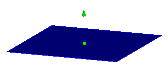
The first way to specify a plane is to specify a starting point and a direction vector:
draw plane location 1 2 3 direction 0 1 1
draw plane vertex 1 direction tangent at curve 1
Figure 1. Specifying a plane with a location and surface normal
To see the options for location specification, see Specifying a Location. Direction options can be found at Specifying a Direction.
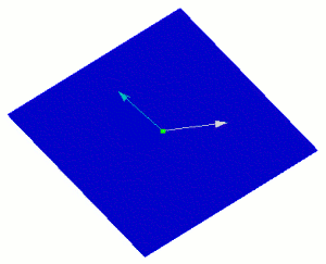
{Location|Vertex|Node} <origin> Direction <vec on plane> Direction <vec on plane>
It is also possible to select an origin point and 2 direction vectors on the plane.
 .
.
Figure 2. Specifying a plane with a point and 2 in-plane vectors
{Location|Vertex|Node} <2 locations> Direction <vector on the plane>
You can also specify 2 locations and 1 direction on the plane to define the plane.
draw plane vertex 1 2 direction 0 1 1
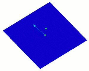
Figure 3. Specifying 2 locations and 1 direction on the plane
{Location|Vertex|Node} <3 locations>
A plane can be defined by three locations, vertices, or nodes. The locations are specified using Location Specification.
draw plane vertex 1 2 3
draw plane vertex 1 2 location 3 4 5
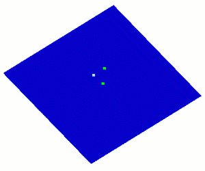
Figure 4. A plane specified by three points
Surface <id> [At Location <loc>]
The surface option uses and existing surface to define the plane. If it is not a planar surface, the optional location specifier can be used to find the tangent plane of a specific point on the surface.
draw plane surface 1 at location 4 0 0
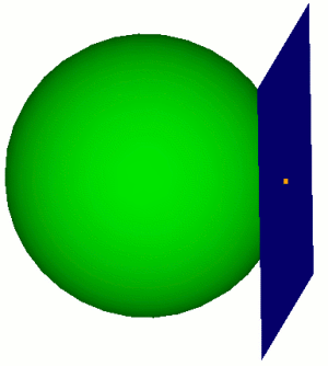
Figure 5. Specifying a Tangent plane to a Surface
[Normal To] Curve <id> [loc on curve options]
The Normal to Curve option allows you to define a plane by using an existing curve. The direction of the curve will define the surface normal of the new plane. The optional location argument specifies which point to use on the curve if it is not a straight curve. If no location is specified the plane will originate at the midpoint of the curve. See Specifying a Location on a Curve for more information on location options.
brick x 10
cylinder radius 3 z 12
subtract body 2 from 1
webcut body 1 xplane
draw plane normal to curve 30
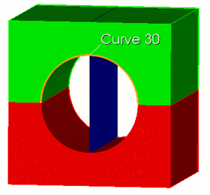
Figure 6. Draw Plane Normal to Curve
A plane can be defined by a single curve, provided that curve is not linear.Arc Curve <id>
cylinder height 12 radius 3
draw plane arc curve 2
A plane can be defined by a two linear curves, provided that the curves are not co-linear.Linear Curve <id> <id>
brick x 10
draw plane linear curve 2 3
Direction <Normal> Coefficient <val>
The direction and coefficient option allows you to specify a plane based on a vector and an offset from the origin. The Coefficient argument specifies how far to offset the plane from the origin
draw plane direction 1 2 3 coefficient 3
X|Xplane|Yz|Zy|Y|Yplane|Zx|Xz|Z|Zplane|Xy|Yx
A plane can be defined from any coordinate plane or combination thereof. The coordinate planes will pass through the origin unless optional specifiers are included.
draw plane xplane
webcut volume 1 plane xz
Last
The last option will return the plane most recently used in a command. Last locations do not carry over from CUBIT session to CUBIT session. The last location defaults to (0, 0, 0) if no location has been used during the session.
The following options apply to all of the plane specification methods described above.
- [Offset <val>]
- [Move {<xval yval zval>| {Dx|X|Dy|Y|Dz|Z} <val> | Direction {options} [Distance <val>]]
- [[To] Location {options}]
- [Spin [About] Axis {options} Angle <ang>]]
A offset value will offset the plane in the direction of the surface normal.
The move option will displace the plane in the specified directions by the specified distance. The direction options are outlined on Specifying a Direction.
The location option will move the plane to a specified location without rotating it. See Specifying a Location for location options.
The spin option will rotate the plane around an axis. See Specifying an Axis for axis options.
The options for specifying a plane are described above in the section on Plane Specification. By default, the commands draw the plane just large enough to intersect the bounding box of the entire model with minimum surface area. Optionally, you can give a list of bodies to intersect for this calculation. You can also extend the size of the surface by either a percentage distance or an absolute distance of the minimum area size. The default color is blue, but you can specify a different one. See the Appendix of the CUBIT Users Guide for available colors in CUBIT.Draw Plane (options) [Graphics | {[Intersecting] {Body|Volume} <id_range>] [ [Extended] {Percentage|Absolute} <val>]}] [Color 'color_name']
Draw Cylinder Radius <val> Axis {x|y|z|Vertex <id_1> Vertex <id_2> | <xyz values>} [Center <x_val> <y_val> <z_val>] [[Intersecting] Body <id_range>] [Extended Percentage|Absolute <val>] [Color 'color_name']
The cylinder is defined by a radius and the cylinder axis. The axis is specified as a line corresponding to a coordinate axis, the normal to a specified surface, two arbitrary points, or an arbitrary point and the origin. The center point through which the cylinder axis passes can also be specified.
By default, the commands draw the cylinder just large enough to just intersect the bounding box of the entire model. Optionally, you can give a list of bodies to intersect for this calculation. You can also extend the length of the cylinder by either a percentage distance or an absolute distance of the cylinder length. The default color is blue, but you can specify a different one. See the Appendix of the CUBIT Users Guide for available colors in CUBIT.