Cubit 15.9 User Documentation
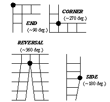
Several meshing algorithms in CUBIT "classify" the vertices of a surface or volume to produce a high quality mesh. This classification is based on the angle between the edges meeting at the vertex, and helps determine where to place the corners of the map, submap or trimesh, or the triangles in the trimap or tripave schemes. For example, a surface mapping algorithm must identify the four vertices of the surface that best represent the surface as a rectangle. Figure 1 illustrates the vertex angle types for mapped and submapped surfaces, and the correspondence between vertex types and the placement of corners in a mapped or submapped mesh.

Figure 1. Angle Types for Mapped and Submapped Surfaces: An End vertex is contained in one element, a Side vertex two, a Corner three, and a Reversal four.
The surface vertex type is computed automatically during meshing, but can also be specified manually. In some cases, choosing vertex types manually results in a better quality mesh or a mesh that is preferable to the user. Vertex types can be specified directly as End, Side, Corner, or Reversal, or can be specified by giving the desired interior angle as 90, 180, 270, or 360, respectively.
Vertex types have a firmness, just as meshing schemes do. Automatically selected vertex types are soft, while user-set vertex types are hard.
Vertex types are set using the following commands:
Surface <surface_id> [Vertex <vertex_id_range> [Loop_index <int>]] Type {End|Side|Corner|Reversal}
Surface <surface_id> [Vertex [<vertex_id_range> [Loop_index <int>]] Angle <value>
Surface <surface_id> [Vertex <vertex_id_range> [Loop_index <int>]] Type {Default|Soft|Hard}
If no vertices are specified, the command is applied to all vertices of each surface.
Note that a vertex may be connected to several surfaces and its classification can be different for each of those surfaces.
The influence of vertex types when mapping or submapping a surface is illustrated in Figure 2. There, the same surface is submapped in two different ways by adjusting the vertex types of ten vertices.
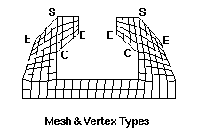
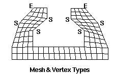
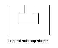
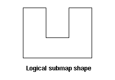
Figure 2. Influence of vertex types on submap meshes; vertices whose types are changed are indicated above, along with the mesh produced; logical submap shape shown below.
The loop_index is an advanced option used only for vertices where the boundary of a single surface passes through the same vertex more than once. This case is not common. If no loop index is specified for such a vertex, the specified vertex type is assigned to all occurrences of the vertex. The loop index for a specific occurrence of a vertex can be determined by listing the surface (list surface <id>) to show the list of curves in each loop bounding the surface, with the start and end vertex listed for each curve. The loop index begins at zero for the first curve in the first loop, and is incremented by one for subsequent curves through the last curve in the last loop. The loop index values corresponding to a specific vertex will be the loop index of each curve whose start vertex is the desired vertex.
Listing a surface lists the types of the vertices. The vertex type settings may also be drawn with the following commands:
Draw Surface <surface_id_range> {Vertex Angle|Vertex Type}
For a surface that will be meshed with scheme trimap or tripave, the user may specify the angle below which triangles are inserted:
Surface <surface_id_range> Angle <angle>
The user may also set whether to add a triangle at a particular vertex:
Surface <surface_id> [Vertex <vertex_id_range> [Loop_index <int>]] Type {Triangle|Nontriangle}
The user may specify the maximum allowable angle at a corner with the following command:
Set {Corner|End} Angle <degrees>
The user may also give greater priority to one automatic selection criteria over the others by changing the following absolute weights. The corner weight considers how large angles are at corners. The turn weight considers how L-shaped the surface is. The interval weight considers how much intervals must change. The large angle weight affects only auto-scheme selection: surfaces with a large angle will be paved instead. Each weight's default is 1 and must be between 0 and 10. The bigger a weight the more that criteria is considered.
Set Corner Weight <value>
Set Turn Weight <value>
Set Interval Weight <value>
Set Large Angle Weight <value>
An illustration of a mesh produced by the submapping algorithm is shown in Figure 2. The meshes produced by submapping on the left and right result from adjusting the vertex types of the eight vertices shown.
When sweeping, a 2.5 dimensional meshing scheme, curves perpendicular to the sweep direction can have a type with respect to the volume. These types are usually automatically selected. The following commands are useful:
Draw Volume <surface_id_range> {Curve Angle|Curve Type}
List Volume <volume_id> Curve Type
Volume <volume_id> [Curve <curve_id_range>] Type {End|Side|Corner|Reversal}
Volume <volume_id> [Curve <curve_id_range>] Type {Default|Soft|Hard}