Example of surface pillowing, before and after smoothing
Cubit 15.9 User Documentation
Sculpt options for modifying the mesh to improve mesh quality.
Automatic smoothing provides an effective method for improving element quality. However there may be some cases that cannot be improved with smoothing alone. The options included in this section will apply changes to the underlying hex mesh or to the volume fraction data to increase the opportunity for smoothing to produce a good quality mesh.
Mesh Improvement             -imp     --improve
  --pillow                   -p    <arg> Set pillow criteria (1=surfaces)
  --pillow_surfaces          -ps         Turn on pillowing for all surfaces
  --pillow_curves            -pc         Turn on pillowing for bad quality at curves
  --pillow_boundaries        -pb         Turn on pillowing at domain boundaries
  --pillow_curve_layers      -pcl  <arg> Number of elements to buffer at curves
  --pillow_curve_thresh      -pct  <arg> S.J. threshold to pillow hexes at curves
  --pillow_smooth_off        -pso        Turn off smoothing following pillow operations
  --capture                  -c    <arg> Project to facet geometry <beta>
  --capture_angle            -ca   <arg> Angle at which to split surfaces <beta>
  --capture_side             -sc   <arg> Project to facet geometry with surface ID
  --defeature                -df   <arg> Apply automatic defeaturing
  --min_vol_cells            -mvs  <arg> Minimum number of cells in a volume
  --defeature_bbox           -dbb        Defeature Filtering at Bounding Box
  --defeature_iters          -dfi  <arg> Maximum Number of Defeaturing Iterations
  --thicken_material         -thm  <arg> Expand a given material into surrounding cells
  --thicken_void             -thv  <arg> Insert void material to remove overlap
  --micro_expand             -me   <arg> Expand Microstructure grid by N layers
  --micro_shave              -ms         Remove isolated cells at micro. boundaries
  --remove_bad               -rb   <arg> Remove hexes with Scaled Jacobian < threshold
  --wear_method              -wm   <arg> Method for removing void at free surface
  --crack_min_elem_thickness -cmet <arg> Minimum element thickness in crack

Sculpt Command Summary
Command: pillow     Set pillow criteria (1=surfaces)

Input file command:   pillow <arg>
Command line options: -p <arg>
Argument Type:        integer (0, 1, 2, 3)
Input arguments: off (0)
                 surfaces (1)
                 curves (2)
                 domain_boundaries (3)
                 surfaces_no_smoothing (100)
                 curves_2_layers (212)
                 curves_3_layers (213)
                 curves_4_layers (214)
                 curves_5_layers (215)
                 curves_2_layers_no_smoothing (202)
                 curves_3_layers_no_smoothing (203)
                 curves_4_layers_no_smoothing (204)
                 curves_5_layers_no_smoothing (205)
Command Description:
For models that have more than one material that share an interface, unless the geometry is precisely aligned with the global axis, it is usually a good idea to turn on pillowing. Pillowing automatically inserts an additional layer of hexes at interface boundaries to improve mesh quality. Without pillowing you may notice inverted or poor quality elements at curve interfaces where 2 or more materials meet.
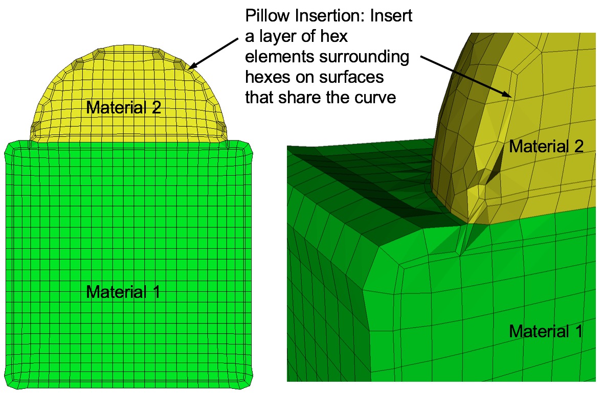
The pillow option will generate an additional layer of hexes at surfaces as a means to improve element quality near curve interfaces. This is intended to eliminate the problem of 3 or more nodes from a single hex face lying on the same curve. Use one or more of the following options to set up pillowing:
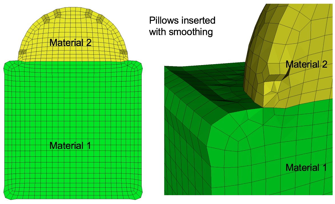
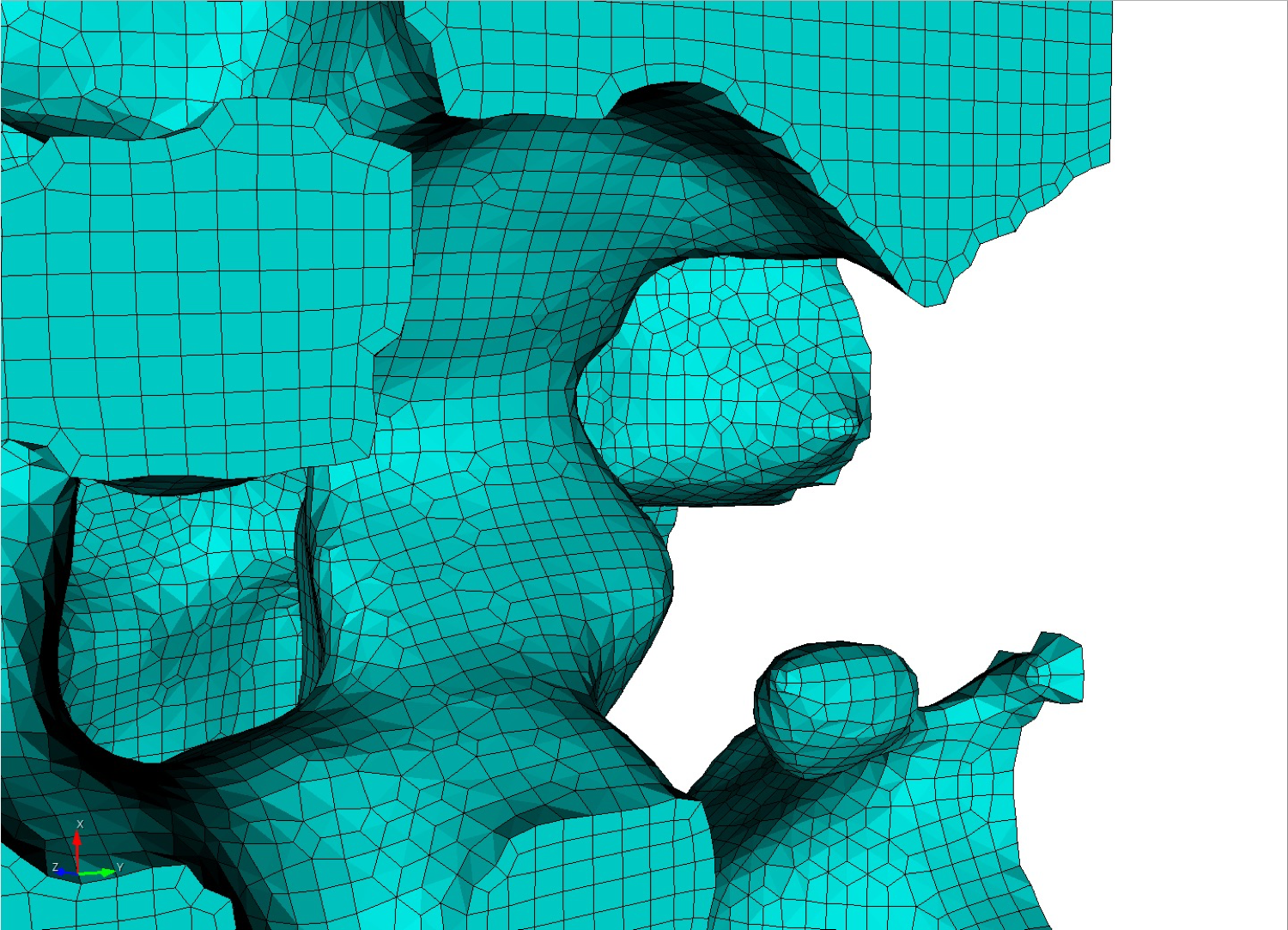
Command: pillow_surfaces     Turn on pillowing for all surfaces

Input file command:   pillow_surfaces
Command line options: -ps
Command Description: Pillow option to insert a layer of hexes surrounding each internal surface in the mesh. Where two volumes share a common interface is defined as a surface. All hexes that have at least one of its faces on a surface are defined as the "shrink set" of hexes. A separate shrink set is defined for each unique surface. Hexes in the set are shrunk away from their hex neighbors not in the shrink set. A layer of hexes is then inserted surrounding all hexes in each set. This enforces the condition where no more than one hex edge will lie on any single curve thus allowing more freedom for the smoother to improve element quality.
Example of surface pillowing, before and after smoothing
Surface pillowing is off by default. If both pillow_curves and pillow_surfaces options are used, curve pillowing will be performed before surface pillowing. See the pillow option for more information on setting additional options for pillowing.
Command: pillow_curves     Turn on pillowing for bad quality at curves

Input file command:   pillow_curves
Command line options: -pc
Command Description: Pillow option to selectively pillow hexes at curves. Only hexes that have faces with 3 or more nodes on a curve will be pillowed. Additional buffer layers of hexes beyond the poor quads at the curves will be included in the pillow region. The number of buffer layers beyond the curve can be controlled with the pillow_curve_layers, where the default will be 3 layers.
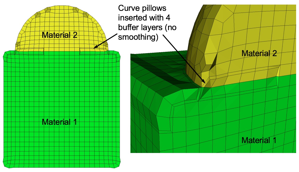
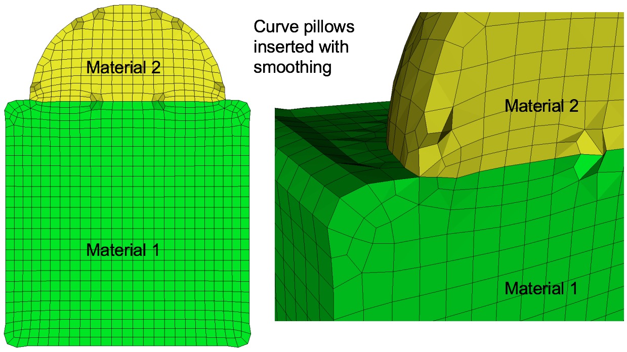
Example of curve pillowing with four pillow_curve_layers, before and after smoothing
Curve pillowing is off by default. If both pillow_curves and pillow_surfaces options are used, curve pillowing will be performed before surface pillowing. See the pillow option for more information on setting additional options for pillowing.
Command: pillow_boundaries     Turn on pillowing at domain boundaries

Input file command:   pillow_boundaries
Command line options: -pb
Command Description: Pillow option to insert pillow layers at domain boundaries of the initial Cartesian grid definition. One layer of hexes is inserted on each of the six faces of the Cartesian Domain. This option is useful where the void option is used to generate a mesh in the full Cartesian grid and where the adapt option has been used. Without this option, it is likely that hexes with two faces on the same domain boundary will occur if the adaptation extends to the boundary. Turning on the pillow_boundaries option should correct for these cases.
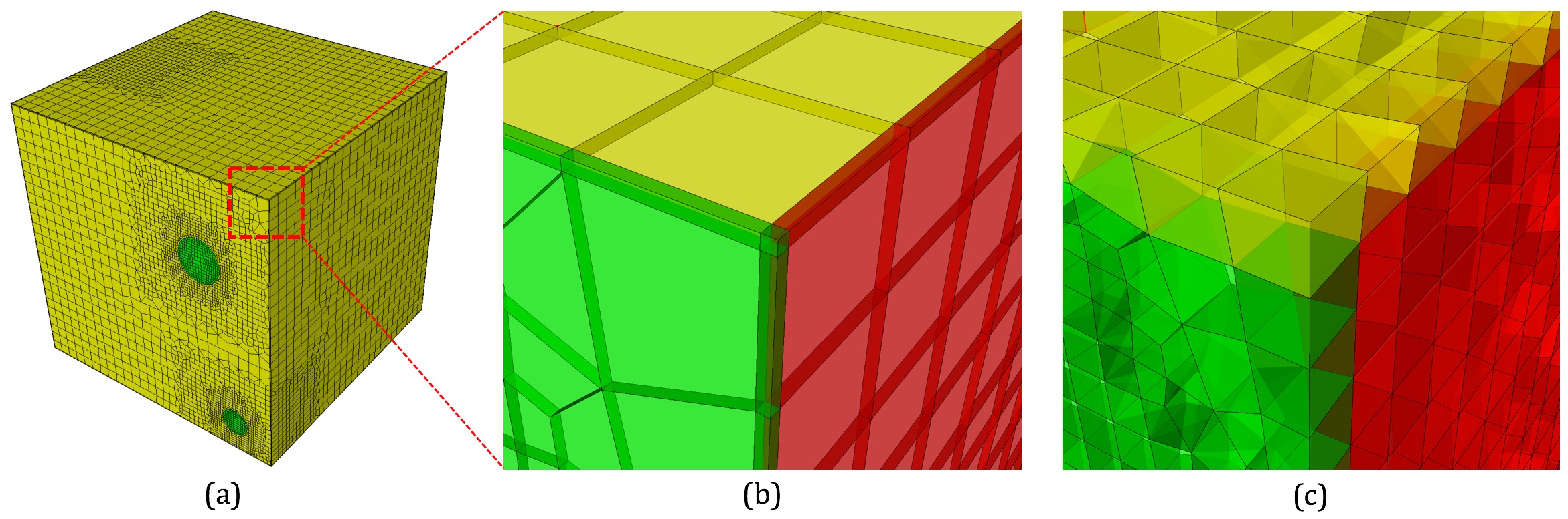
Example of pillowing at boundaries on a microstructure RVE. (b) before smoothing (c) after smoothing
Boundary pillowing is off by default. The pillow_boundaries option may be used in the same input as pillow_surfaces or pillow_curves. The pillow_boundaries option must also be used with the mesh_void option to ensure hexes will exist at the Cartesian domain boundary. See the pillow option for more information on setting additional options for pillowing.
Command: pillow_curve_layers     Number of elements to buffer at curves

Input file command:   pillow_curve_layers <arg>
Command line options: -pcl <arg>
Argument Type:        integer > 0
Command Description: Used for setting the number of buffer hex layers when the pillow_curves option is used. When pillow_curves is used a shrink set is formed from hexes that would otherwise have two or more edges on the same curve. This value will control the extent to which neighboring hexes will be included in the shrink set. The default pillow_curve_layers is 3. Setting this value lower will localize the modifications to the hex mesh, whereas, more layers will extend the region that is affected in correcting the poor quality at curves.
Command: pillow_curve_thresh     S.J. threshold to pillow hexes at curves

Input file command:   pillow_curve_thresh <arg>
Command line options: -pct <arg>
Argument Type:        floating point value (-1.0->1.0)
Command Description: Used for setting the quality threshold for pillowing hexes at curves. When determining hexes to include in the shrink set, the pillow_curves option will look for hexes with more than two nodes of a hex on the same curve. If this condition is satisfied, it will test the mesh quality of quads on the adjacent surfaces that share the common curve. If at least 3 nodes are on a common curve and the Scaled Jacobian of any of the attached quads falls below the, pillow_curve_thresh scaled Jacobian metric, then the associated hexes will be included in the shrink set.
Default for pillow_curve_thresh is 0.3. Increasing this value will tend to increase the total number of hexes added to the mesh, but may result in better mesh quality after smoothing. Lowering this value may reduce the number of additional hexes but could potentially result in more hexes with poor or bad Scaled Jacobian metrics.
Command: pillow_smooth_off     Turn off smoothing following pillow operations

Input file command:   pillow_smooth_off
Command line options: -pso
Command Description: Controls the smoothing following pillow operations. To maximize element quality at pillowed hexes, smoothing is always performed after inserting the hex layers. The smoothing step may be omitted if pillow_smooth_off is set. This option can be useful for visualizing the pillow layers that have been inserted, but in most cases will generate poor quality or inverted elements.
Command: capture     Project to facet geometry <beta>

Input file command:   capture <arg>
Command line options: -c <arg>
Argument Type:        integer (0, 1, 2)
Input arguments: off (0)
                 on (1)
                 external_surfaces (2)
                 projections_only (3)
                 feature_angle_smooth (4)
                 topology_smooth (5)
Command Description:
This is an experimental option still in development. Nodes at the surfaces of a default sculpt mesh will not necessarily exactly lie on the geometric surfaces prescribed by the input STL geometry. While this characteristic can provide additional flexibility for defeaturing and element quality, there are cases where a more exact surface representation may be desired. The capture option attempts to address this by extracting sharp features and/or projecting nodes to the facet geometry.
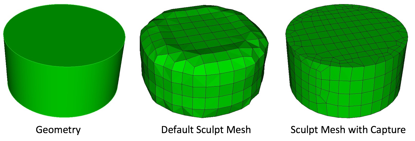
Simple example illustrating the effect of the capture = 5 option. Options smooth = to_geometry and pillow_curves = true are also used for this example.
0 = (off) Capture option is off. No attempt is made at capturing sharp features.
1 = (on) STL geometry is used as basis for feature capture. A user defined feature angle is used (capture_angle) to first generate groups of facets from the STL geometry based on capture_angle. Topological curves are defined based on projections to closest surface facets and edges. With default smoothing option, the surface nodes will be projected to the closest STL surfaces as a final step before exporting the exodus mesh. Consider using smooth = to_geometry option.
2 = (exterior_surfaces) Only exterior surfaces are captured. Uses the same procedure as described in capture = 1, except that interior surfaces (those with two adjacent volumes), will be ignored in the capture and projections stage.
3 = (projections_only) For this option, additional topology based on feature angle is not extracted. Only the final projection of surface nodes to the STL facets is done. Note that this option is useful for organic shapes that do not have sharp features, or where sharp features should be ignored.
4 = (feature_angle_smooth) This option uses the procedure outlined in capture = 1, except that the smooth = to_geometry is used by default. Note that capture = 1 used with smooth = to_geometry should be identical to this option.
5 = (topology_smooth) Curve topology is defined similar to capture = 1, except that element face topology is first determined based on closest assigned facet. Curve topology is then extracted based on adjacent element face associativity. Surface node projections are only done for nodes that have unambiguous neighbor associativity. This provides for a tolerant approach to resolving topology that may result in defeaturing. (i.e. where the STL facet topology may be locally more complex than can be resolved by the prescribed resolution). This option also uses the smooth = to_geometry option as default for smoothing. Also note that capture = 5 it is only currently available for serial execution (j=1)
Command: capture_angle     Angle at which to split surfaces <beta>

Input file command:   capture_angle <arg>
Command line options: -ca <arg>
Argument Type:        floating point value (0 -> 360)
Command Description:
This is an experimental option still in development. Feature angle for capture option.
Command: capture_side     Project to facet geometry with surface ID

Input file command:   capture_side <arg>
Command line options: -sc <arg>
Argument Type:        integer > 0
Command Description:
Similar to the capture option, the capture_side option will project nodes to the initial triangle facets, however projections will be limited only to surface nodes closest to the surface ID specified by the argument. Note that the input STL file can identify and group facets according to a surface ID. However surface IDs are utilized only when using the gen_sidesets option with arguments 3 and 4. When using Cubit, the STL file written when using the sculpt parallel command with sideset options 3 and 4 will include surface identification for surfaces in the STL file. A workflow for using the capture_side option might include the following:
The result should be a mesh where surface nodes closest to the surfaces identified by the unique sideset ID will lie precisely on their closest surface.
Command: defeature     Apply automatic defeaturing

Input file command:   defeature <arg>
Command line options: -df <arg>
Argument Type:        integer (0, 1, 2, 3)
Input arguments: off (0)
                 filter (1)
                 collapse (2)
                 filter_and_collapse (3)
Command Description:
Option to automatically detect and remove small features. Primarily used for defeaturing microstructure data, however can be used with any input format. The following options are available:
See also the defeature_iters and defeature_bbox options for additional control of the defeature = filter option. The compare_volume option can also be used to validate that changes made to material volumes are within acceptable limits.
Example grid cells before and after defeaturing has been applied
Final mesh after using defeaturing.
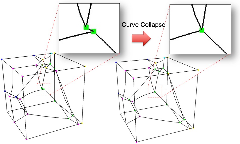
Example collapsing of small curve on microstructure model when using defeature=2 and trimesh option
Command: min_vol_cells     Minimum number of cells in a volume

Input file command:   min_vol_cells <arg>
Command line options: -mvs <arg>
Argument Type:        integer >= 0
Command Description:
When used with defeature options filter (1) or filter_and_collapse (3), specifies the minimum number of cells below which a volume will be eliminated. The cells of small volumes will be absorbed into the predominant material of the neighboring cells. If not specified and defeature options filter (1) or filter_and_collapse (3) are used, the min_vol_cells value will be set to 5.
Command: defeature_bbox     Defeature Filtering at Bounding Box

Input file command:   defeature_bbox
Command line options: -dbb
Command Description:
The defeature_bbox option is used in conjunction with defeature = filter (1). It is used to modify the defeature filter criteria at cells that are immediately adjacent to the Cartesian grid's domain boundary. It is most effective for microstructure data but can be used with any input format. The defeature = filter (1) option will remove protrusions identified by cells that are surrounded on 4 or 5 sides by another material. For cells that are at the domain boundary, cells will have missing adjacent cells on at least one face. If the defeature_bbox=true option is used, the missing adjacent cells are considered a different material and counted in the 4 or 5 surrounding cells with a different material. In contrast, the defeature_bbox=false option will not count the missing adjacent cells. Using the defeature_bbox=true has the effect of more aggressively modifying cells at the domain boundaries to avoid protrusions. The default for this option is defeature_bbox=false. It will be ignored if defeature = filter (1) is not used.
Command: defeature_iters     Maximum Number of Defeaturing Iterations

Input file command:   defeature_iters <arg>
Command line options: -dfi <arg>
Argument Type:        integer >=0
Command Description:
Used with the defeature option. Controls the maximum number of iterations of defeature filtering that will be performed. Setting this value greater than the default of 10 can be useful for very noisy data where a significant number of iterations will need to be performed to resolve the geometry.
When performing non-manifold resolution, the defeature state of some of the cells may be effected. As a result, the defeaturing and non-manifold resolution procedures are performed in a loop until no further changes can be made. The defeature_iters sets the maximum number of defeature and non-manifold resolution procedures that will be performed. Note that if defeaturing reaches the maximum iteration value without completely resolving all non-manifold conditions, that subsequent sculpt procedures may not succeed. Set this value higher to allow the defeaturing and non-manifold resolution to run to completion. The stair = 1 option can be used to interrogate the model to see where non-manifold conditions may still exist.
Command: thicken_material     Expand a given material into surrounding cells

Input file command:   thicken_material <arg>
Command line options: -thm <arg>
Argument Type:        integer >= 0 floating point value (0.0->1.0)
Command Description:
Add additional cells at the boundary of a given material. Takes two input values, a material and a volume fraction between 0 and 1. This option is useful for noisy input data that may not form contiguous volumes. Thickening a material may close small gaps making the material continuous. To perform the thicken operation, cells in adjacent materials are removed and reassigned to the indicated material. This option requires both a valid material ID and volume fraction value, where the volume fraction represents the amount of material to be added to each neighboring cell. For example:
thicken material = 1 0.2
thicken_material = 2 0.5
each neighboring cell to material 1 will change approximately 20 percent of its volume to be material 1. Other materials present in the cell will be decreased accordingly to maintain a sum of 1.0 for each cell. Additional material is accumulated in neighboring cells from each adjacent cell it shares with material 1, so that if for example a neighbor cell shares faces with three cells of material 1, it will add 0.6 (0.2 X 3) of material 1 volume fraction to the neighbor. If more than one thicken_material option is used, the thicken operation will be performed in the order they appear in the input. For the above example, material 1 would first be thickened, followed by material 2. If materials 1 and 2 are adjacent, thickening in this case, material 2 would take precedence, potentially removing cells from material 1 at their interface.
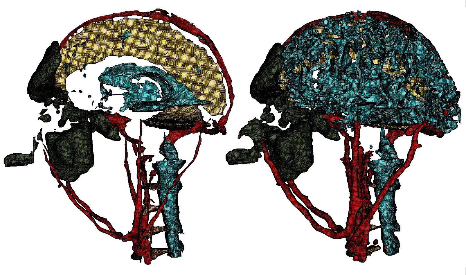
Bitmap input is used on a Cartesian base grid to generate the mesh for complex head and brain anatomy. Left: Some of the materials prior to applying the thicken_material option. Right: After applying the thicken_material option.
Command: thicken_void     Insert void material to remove overlap

Input file command:   thicken_void <arg>
Command line options: -thv <arg>
Argument Type:        floating point value (0.0->1.0)
Command Description:
Add additional void material when non-void material is detected as touching or immediately adjacent. Takes one input value, a volume fraction normally about 1.0 that indicates the quantity of volume fraction inserted at each node if the input grid where non-void material adjacency is detected. A value of 1.0 indicates void material equal to the volume of one cell will be added at the nodes, reducing the volume fractions of other materials present in adjacent cells. Smaller input values will generate a smaller gap between materials, but can run the risk of materials bleeding into one another.
This option is useful when it is known that non-void materials in the model should not touch, instead should have a gap where they would otherwise touch or overlap. For example:
thicken_void = 1.0
each node where its adjacent cells have two or more non-void materials present will have additional void material added. In this case, if 8 adjacent cells are assumed, a contribution of 1/8 void volume fraction will be added to each adjacent cell to the node. Other materials present in the cells will be decreased accordingly to maintain a sum of 1.0 for each cell.

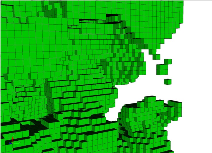
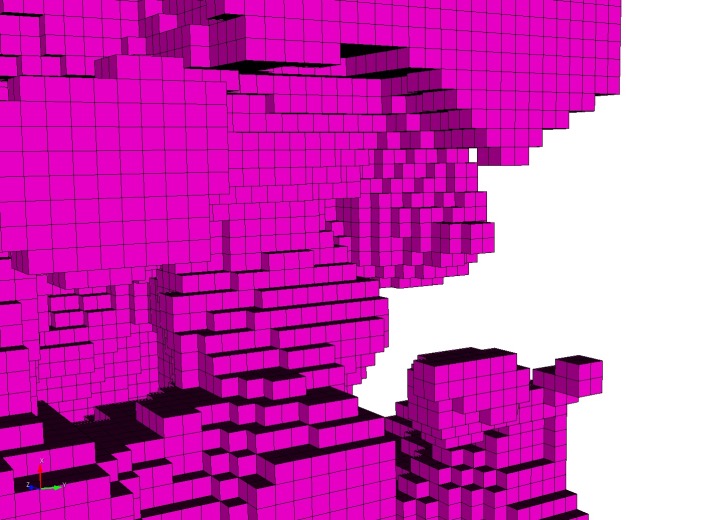
Left: Initial mesh without thicken_void. Right: Mesh with thicken_void=1. Void material (Magenta elements) is inserted between the yellow and green materials to ensure separation.
Command: micro_expand     Expand Microstructure grid by N layers

Input file command:   micro_expand <arg>
Command line options: -me <arg>
Argument Type:        integer >= 0
Command Description:
This option expands the Cartesian grid by a specified number of layers. It can be used with any of the following input options:
    --input_micro
    --input_cart_exo
    --input_spn
In some cases the interior material interfaces may intersect the domain boundaries at small acute angles. When this occurs it may be difficult or impossible to achieve computable mesh quality at these intersections. To address this problem, one or more layers of hexes may be added to the Cartesian grid. The volume fractions from cells at the boundary are copied to generate additional layers. This has the effect of increasing the angle of intersection for any material interfaces intersecting the domain boundary. Usualy a value of 1 or 2 is sufficient to sufficiently improve quality.
Note that the resulting mesh in the expanded layers serves only to improve mesh quality and will only duplicate existing data at the boundaries. It may not reflect the actual material structure within the expansion layers.
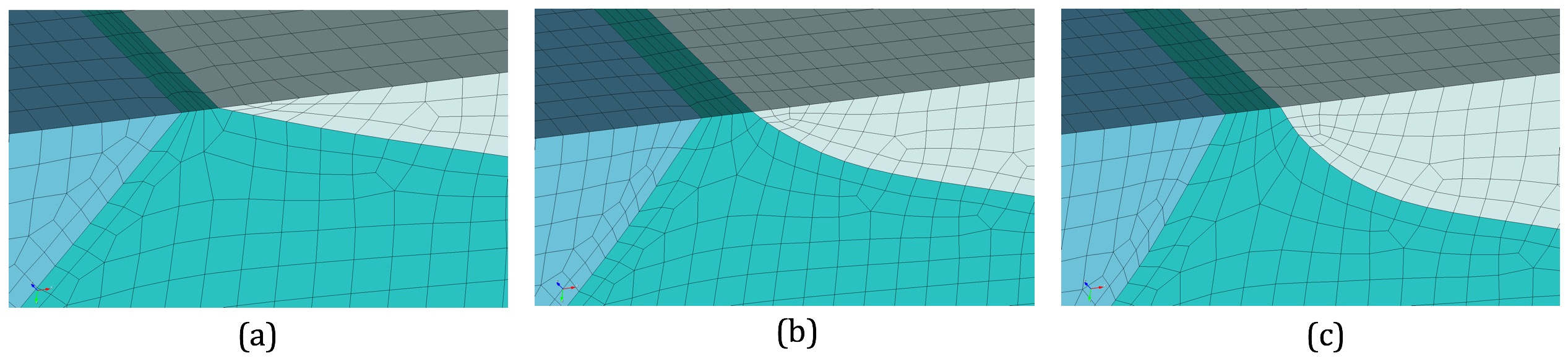
(a) Initial mesh (b) One expansion layer added (c) Two expansion layers added
Command: micro_shave     Remove isolated cells at micro. boundaries

Input file command:   micro_shave
Command line options: -ms
Command Description:
This option potentially modifies the outermost layer of Cartesian cells of a microstructures file. It will identify isolated cells where the assigned material is unique from all of its surrounding cells at the boundary. When this occurs, the cell material is reassigned to the dominant nearby material.
This option is useful if it is noted that a cell structure just barely grazes the exterior planar boundary surface. Poor quality elements can often result with this condition. The micro_shave option will, in effect, remove material from the cell structure, but will result in better quality elements by removing the intersection region with the boundary.
micro_shave can be used with any of the following input options:
    --input_micro
    --input_cart_exo
    --input_spn
Command: remove_bad     Remove hexes with Scaled Jacobian < threshold

Input file command:   remove_bad <arg>
Command line options: -rb <arg>
Argument Type:        floating point value -1.0 >= 1.0
Command Description:
Remove hexes below the specified scaled Jacobian metric.
Command: wear_method     Method for removing void at free surface

Input file command:   wear_method <arg>
Command line options: -wm <arg>
Argument Type:        integer (0, 1, 2)
Input arguments: cell (0)
                 cell (1)
                 sheet (2)
Command Description:
This option defines how the mesh removes void elements that are at the free_surface_sideset. Used with the free_surface_sideset, input_mesh and capture=5 options. Normally with the default wear_method = cell (0) option, elements in the input_mesh outside of the specified free_surface_sideset are removed when the percent of its volume (volume fraction) lying outside of the free_surface_sideset exceeds 50 percent. If the wear_method = sheet (2) option is set, volume fraction of continuous layers of elements (sheets) that lie at the free_surface_sideset can be removed. The entire sheet of elements will be retained or removed based on the total volume fraction of the elements in the sheet. The wear_method = sheet (2) option is most useful when used with a swept input_mesh where the free_surface_sideset is approximately orthogonal to the sweep direction. It can especially improve mesh quality when using the capture=5 option where small geometric features, such as cracks, are encountered near the free_surface_sideset. See also the crack_min_elem_thickness option, to control how cracks are captured at the free_surface_sideset.
Command: crack_min_elem_thickness     Minimum element thickness in crack

Input file command:   crack_min_elem_thickness <arg>
Command line options: -cmet <arg>
Argument Type:        floating point value
Command Description:
Defines the minimum allowed thickness of the elements resolving the side of a crack. Used with the wear_method = sheet (2) and match_sideset options to potentially improve mesh quality at cracks near the free_surface_sideset. Cracks are normally identified using the match_sideset and match_sidesets_nodset options. The distance from the bottom of the crack to the free_surface_sideset is measured to determine the element thickness. If the thickness is below the specified crack_min_elem_thickness value, the crack walls are merged together at this location. If a crack_min_elem_thickness is not specified, cracks near the free_surface_sideset will only be collapsed when the surrounding volume fraction of the sheet drops below 50 percent.