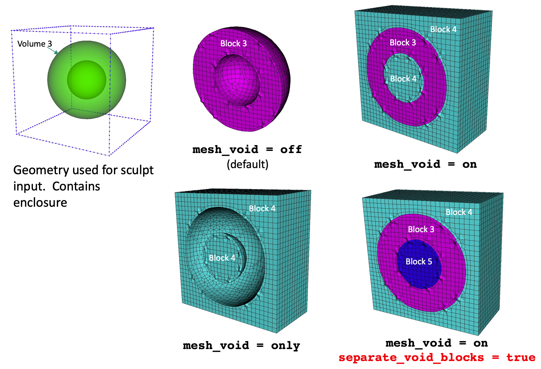
Example of the effect of using separate_void_blocks with the mesh_void option
Cubit 15.9 User Documentation
Sculpt options for specifying the methods for generating nodesets, sidesets and blocks on the mesh. Several automatic methods for generating nodesets and sidesets are provided in Sculpt using the gen_sidesets option. Where multiple blocks are required, Block IDs are normally defined using the material ID in the diatom file. Each STL file can be associated with a different block ID. If the mesh_void option is used, the ID for the block of elements in the void region can be set using the void_mat option.
For other input formats such as volume fraction microstructure data or Cartesian Exodus files, the Block IDs are defined by the individual formats.
Boundary Conditions          -bc     --boundary_condition
  --void_mat                 -VM   <arg> Void material ID (when mesh_void=true)
  --separate_void_blocks     -SVB        Separate void into unique block IDs
  --material_name            -mn   <arg> Label Material (Block) with Name
  --sideset_name             -sn   <arg> Label Sideset with Name
  --nodeset_name             -nn   <arg> Label Nodeset with Name
  --sideset                  -sid  <arg> User Defined Sideset
  --nodeset                  -nid  <arg> User Defined Nodeset
  --gen_sidesets             -SS   <arg> Generate sidesets
  --free_surface_sideset     -FS   <arg> Free Surface Sideset
  --match_sidesets           -mss  <arg> Sidesets ids of matching pairs
  --match_sidesets_nodeset   -msn  <arg> Nodeset defining match_sidesets

Sculpt Command Summary
Command: void_mat     Void material ID (when mesh_void=true)

Input file command:   void_mat <arg>
Command line options: -VM <arg>
Argument Type:        integer > 0
Command Description:
When the mesh_void option is used, this value is the material (block) ID assigned to all elements in the void region. If void_mat option is not used, the material ID of elements in the void region will be the maximum material ID in the model + 1. Note that the void_mat may be the same as an existing material in another part of the model.
Command: separate_void_blocks     Separate void into unique block IDs

Input file command:   separate_void_blocks
Command line options: -SVB
Command Description:
When the mesh_void option is used, the default case will generate a single block ID for all elements in the void region. Turning this option ON will separate the elements into unique block IDs where the elements are contiguous. For example, elements in a void region completely enclosed and interior to a volume will be assigned a different block ID to those exterior to the volume. The void_mat option can be used to specify the ID of the first void block. Subsequent blocks will be numbered incrementally from the first void mat ID. If void_mat is not defined, the next highest IDs not used by a material will be used for the void block IDs.
Example of the effect of using separate_void_blocks with the mesh_void option
Command: material_name     Label Material (Block) with Name

Input file command:   material_name <arg>
Command line options: -mn <arg>
Argument Type:        integer and string
Command Description:
Optionally assign a name to a material. Specify a valid material ID followed by a name. This option can be used multiple times to label one or more materials. The material name will be assigned as the block name to be written to the output exodus file. A valid integer representing a material defined in the input should be used. For example, the name will be associated with the material ID identified in the diatom file for a given package. The command will be ignored if a valid matching material is not found.
Note: When using the input_mesh option and input_mesh_material = blocks, block names may be included in the input exodus mesh as part of the exodus block description. If the material_name option is used and exodus blocks names are included in the input file, the specified material name in the sculpt input will be used.
Command: sideset_name     Label Sideset with Name

Input file command:   sideset_name <arg>
Command line options: -sn <arg>
Argument Type:        integer and string
Command Description:
Optionally assign a name to a sideset. Specify a valid sideset ID followed by a name. This option can be used multiple times to label one or more sidesets. For example:
    sideset_name 10 left_faces
    sideset_name 20 right_faces
    sideset_name 30 bottom_faces
    sideset_name 40 top_faces
The assigned sideset name will be written to the output exodus file. A valid integer
representing a sideset to be generated should be used. The sideset ID should refer
to an existing sideset defined using gen_sidesets or sideset options.
Note: When using the input_mesh option and input_mesh_material = blocks, sideset names may be included in the input exodus mesh as part of the exodus sideset description. If the sideset_name option is used and exodus sideset names are included in the input file, the specified sideset name in the sculpt input will be used.
Command: nodeset_name     Label Nodeset with Name

Input file command:   nodeset_name <arg>
Command line options: -nn <arg>
Argument Type:        integer and string
Command Description:
Optionally assign a name to a nodeset. Specify a valid nodeset ID followed by a name. This option can be used multiple times to label one or more nodesets. For example:
    nodeset_name 10 left_nodes
    nodeset_name 20 right_nodes
    nodeset_name 30 bottom_nodes
    nodeset_name 40 top_nodes
The assigned nodeset name be will written to the output exodus file. A valid integer
representing a nodeset to be generated should be used. The nodeset ID should refer
to an existing sideset defined using gen_sidesets or nodeset options.
Note: When using the input_mesh option and input_mesh_material = blocks, nodeset names may be included in the input exodus mesh as part of the exodus nodeset description. If the nodeset_name option is used and exodus nodeset names are included in the input file, the specified nodeset name in the sculpt input will be used.
Command: sideset     User Defined Sideset

Input file command:   sideset <arg>
Command line options: -sid <arg>
Argument Type:        integer and string
Command Description:
Define a sideset (collection of mesh faces) based on a user-defined specification. Requires one integer representing a unique sideset ID and a character string representing a geometry specification. Current supported geometry specifications include: xmin, xmax, ymin, ymax, zmin, zmax. For a mesh defined with an axis-aligned orientation this option will place sidesets at the bounding box boundaries. For example:
    sideset 10 xmin
    sideset 20 xmax
    sideset 30 ymin
    sideset 40 ymax
Note: See also option gen_sidesets = RVE. The gen_sidesets option will automatically define sidesets at boundaries for Cartesian base meshes.
Command: nodeset     User Defined Nodeset

Input file command:   nodeset <arg>
Command line options: -nid <arg>
Argument Type:        integer and string
Command Description:
Define a nodeset (collection of nodes) based on a user-defined specification. Requires one integer representing a unique nodeset ID and a character string representing a geometry specification. Current supported geometry specifications include: xmin, xmax, ymin, ymax, zmin, zmax. For a mesh defined with an axis-aligned orientation this option will place nodesets at the bounding box boundaries. For example:
    nodeset 10 xmin
    nodeset 20 xmax
    nodeset 30 ymin
    nodeset 40 ymax
Command: gen_sidesets     Generate sidesets

Input file command:   gen_sidesets <arg>
Command line options: -SS <arg>
Argument Type:        integer (0, 1, 2, 3, 4, 5)
Input arguments: off (0)
                 fixed (1)
                 variable (2)
                 geometric_surfaces (3)
                 geometric_sidesets (4)
                 rve (5)
                 input_mesh_and_stl (6)
                 input_mesh_and_free_surfaces (7)
                 rve_variable (8)
                 input_mesh (9)
Command Description:
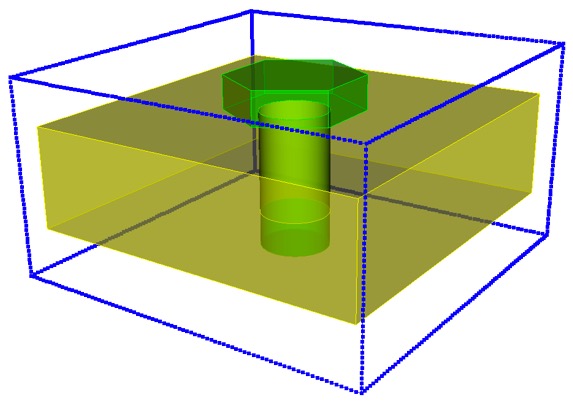
Geometry used in sideset examples below.
Generate exodus sidesets using one of the following options:
off (0): No sidesets will be generated
fixed (1): Exactly 3 sidesets will be generated according to the following:
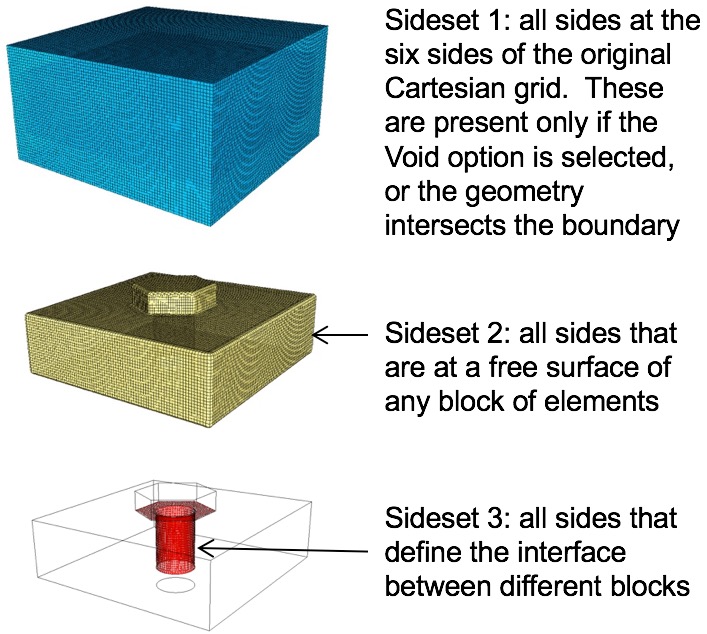
Example of fixed(1) sidesets.
variable (2): A variable number of sidesets will be generated with the following characteristics:
Unlike Fixed sidesets, grouping of sides will be contiguous. A separate sideset will be generated for each set of contiguous sides.
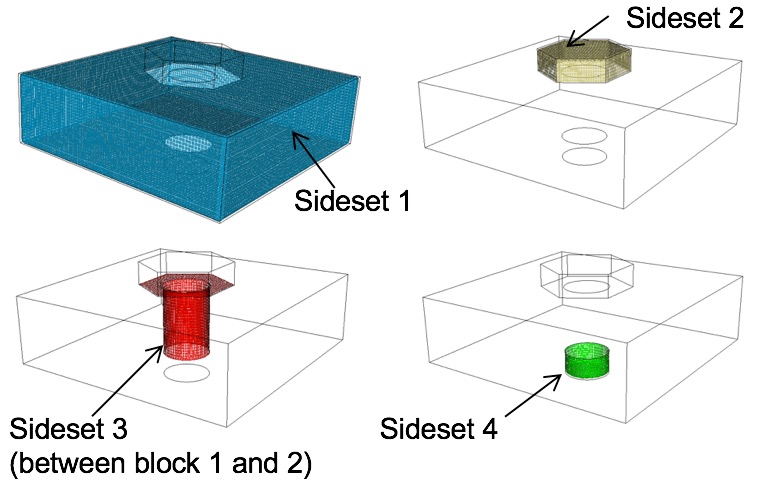
Example of variable(2) sidesets.
geometric_surfaces (3): Sidesets will be generated according to imported surface ID information. STL files may include an optional surface designation for any or all triangles in the file. Surface information may be written automatically from Cubit based on geometric surface IDs or sideset IDs. See the cubit sculpt parallel sideset option for more details. Alternatively, use the "export stl ..." command with the "sidesets" option to export all sidesets in a Cubit model as surface information. If present, one sideset will be generated for each surface designation in the STL file. Following is an example surface designation in an STL file. It would appear following all triangles.
        surface 1
          0 1 2 3 4 5 6 7 8 9
          10 11 12 13 14 15 16 17 18 19
          20 21 22 23
        endsurface 1
The id following the surface designation will be used as the sideset ID. Up to 10 triangle IDs, per line may be assigned to the surface. Triangle IDs are assigned based on order they appear in the STL file. Any number of surfaces may be defined. For this option, the assumption is that all triangles included in the STL files will be included in at least one surface designation.
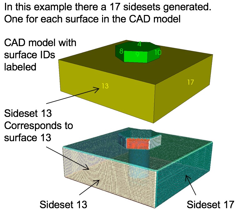
Example of all geometric surfaces (3) defining sidesets.
geometric_sidesets (4): Similar to geometric_surfaces, except that only a portion of the triangles may be designated as sideset surfaces. This option is useful when using Cubit to identify specific surfaces as sidesets.

Example of selected geometric sidesets (4) in Cubit defining sidesets in Sculpt.
RVE (5): When using the full bounding box, such as representative volume elements (RVE) for microstructures, the nodesets and sidesets with IDs 1 to 6 are reserved for the six faces of the bounding box. They are assigned as follows:
        Nodeset/Sideset ID      Contains nodes/faces
               1                on minimum X domain boundary
               2                on maximum X domain boundary
               3                on minimum Y domain boundary
               4                on maximum Y domain boundary
               5                on minimum Z domain boundary
               6                on maximum Z domain boundary
In addition, a nodeset and sideset will be generated on interior surfaces for each unique pair of adjacent material IDs. One final nodeset will also be generated along interior curves at all internal triple junctions (curves where at least 3 surfaces share a common curve).
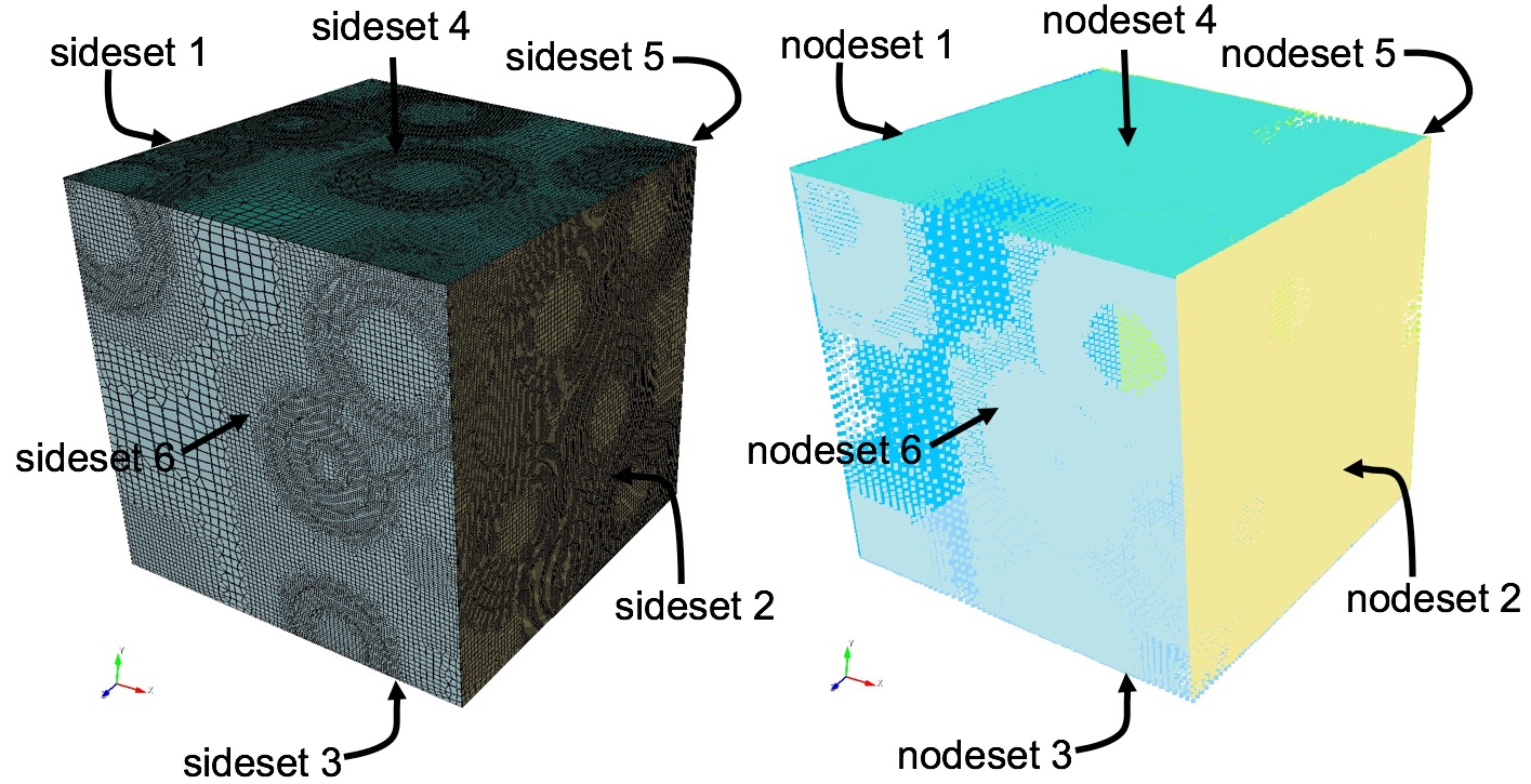
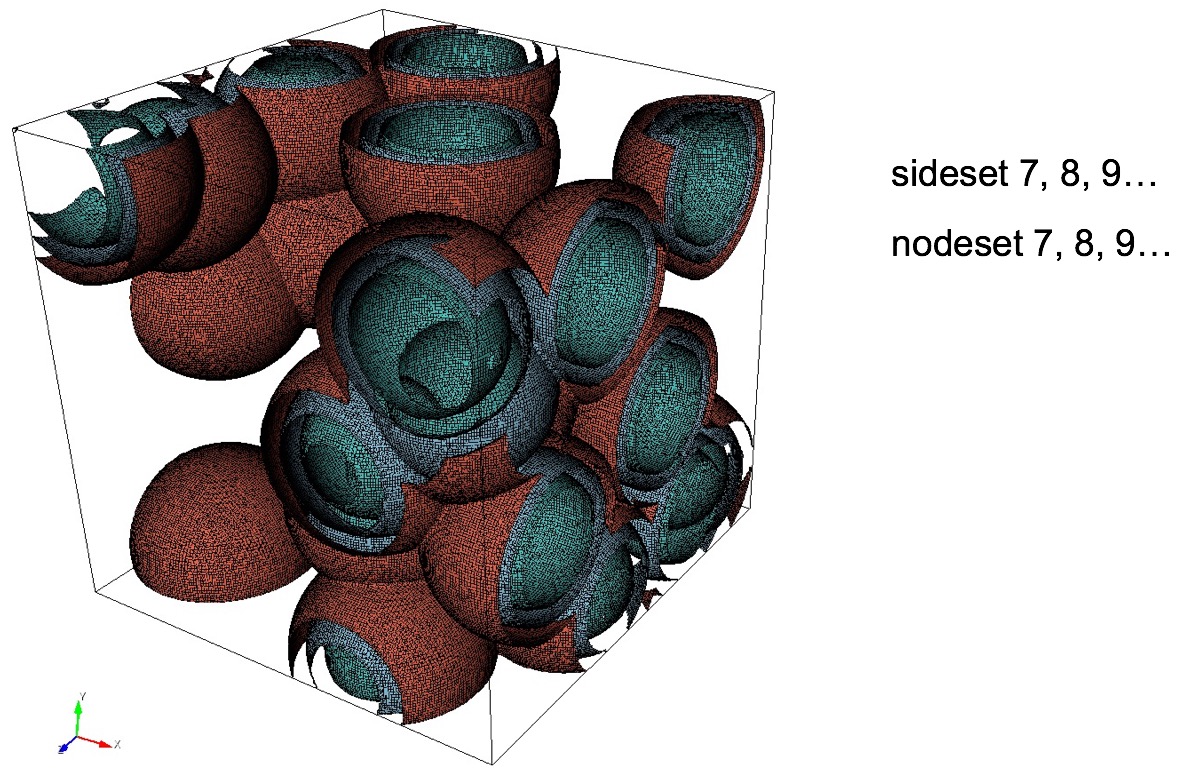
Example of automatically defined sidesets at domain boundaries of an RVE and at all interface surfaces between materials.
input_mesh (9): Used with the input_mesh option where an exodus file is used as the base grid. Only sidesets and nodesets defined in the input exodus mesh are transferred to the output mesh.
input_mesh_and_stl (6): Used with the input_mesh option where an exodus file is used as the base grid. Sidesets and nodesets defined in the input exodus mesh are transferred to the output mesh if the surface is not an interior surface. Sidesets defined in the augmented STL input file are transferred to the output mesh for interior surfaces. See also the free_surface_sideset option for prescribing a sideset on interior surfaces cut by the STL definition when using the input_mesh option.
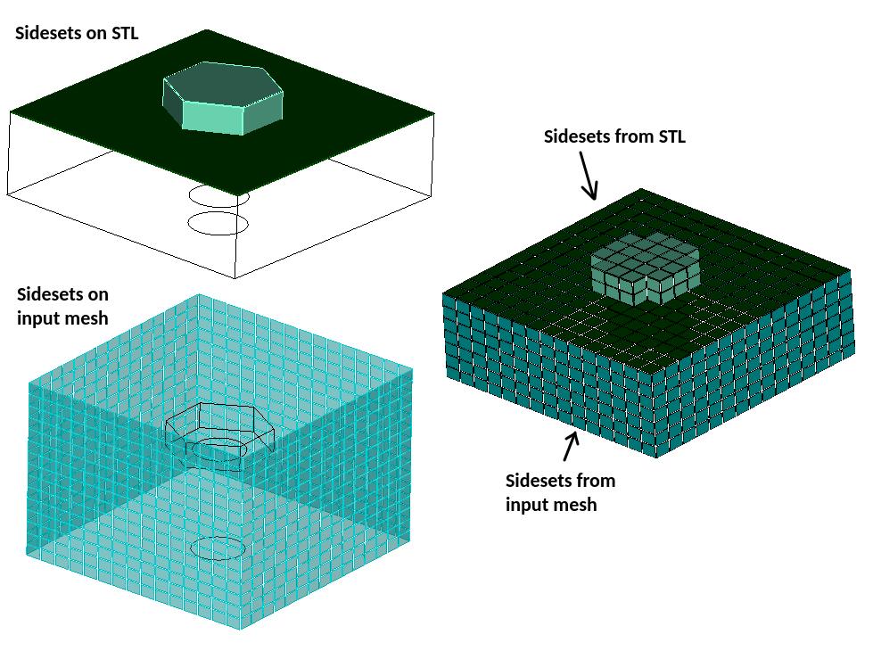
Example of sidesets defined in the input mesh and corresponding domain boundary sidesets in the output mesh.
input_mesh_and_free_surfaces (7): Used with the input_mesh option where an exodus file is used as the base grid. Sidesets and nodesets defined in the input exodus mesh are transferred to the output mesh if the surface is not an interior surface. Sidesets defined in the free_surface_sideset option are used to define sidesets for interior surfaces.
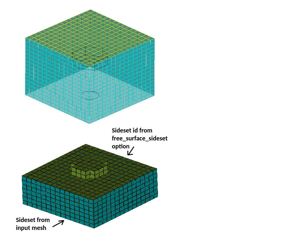
Example of sidesets defined in the input mesh and corresponding domain boundary sidesets in the output mesh.
rve_variable (8): Nodesets 1-6 and Sidesets 1-6 are defined at the boundaries as described in the gen_sidesets = rve (5) option. With the rve_variable option, additional nodesets and sidesets at material interfaces on the interior of the mesh are defined similar to the gen_sidesets = variable (2) option. Grouping of interior sides in a sidesets will be contiguous, where a separate sideset will be generated for each unique set of contiguous sides. Nodesets will be generated in a similar manner.
Command: free_surface_sideset     Free Surface Sideset

Input file command:   free_surface_sideset <arg>
Command line options: -FS <arg>
Argument Type:        integer(s) >= 0
Command Description:
Given exodus sidesets are treated as interior surfaces for STL projection.
Used with the input_mesh option when using an exodus mesh as the base grid. This may be useful if the capture option is enabled and some of the STL surfaces are close in proximity to the boundaries of the input exodus mesh. When close in proximity, sculpt will by default not project those boundary nodes to the STL surface but keep them on the domain boundary. If a list of sideset IDs are given here, the sideset faces will be projected to the STL. The sideset IDs should refer to sidesets that are defined in the specified input_mesh exodus file.
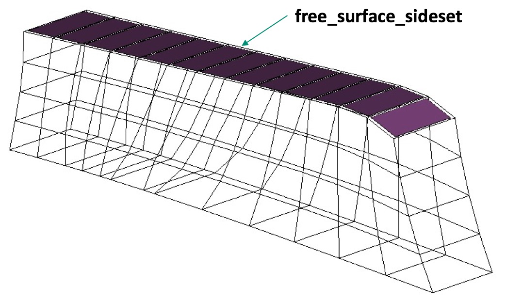
Example of free_surface_sideset defined on the top surface faces of an input mesh
Command: match_sidesets     Sidesets ids of matching pairs

Input file command:   match_sidesets <arg>
Command line options: -mss <arg>
Argument Type:        integer(s) >= 0
Command Description:
If used with an unstructured base grid (input mesh), this option allows the user to define a crack in the input mesh, where the faces of each vertical side (wall) of the crack are each in a different sideset. The faces at the bottom of the crack share a common edge (V-bottom) or face (square-bottom). Sculpt will match or equalize the volume fractions of the bottom cells on either side of the crack. This produces a uniform, higher quality mesh at the crack. The sidesets must be specified in a pairwise order. This option must be used with the --input_mesh (-im) option.
Command: match_sidesets_nodeset     Nodeset defining match_sidesets

Input file command:   match_sidesets_nodeset <arg>
Command line options: -msn <arg>
Argument Type:        integer >= 0
Command Description:
If using the match_sidesets option, this option is used to explicitly define the seam between match_sideset pairs, instead of deriving it. If deriving, the seam is where sideset boundaries share common edges, at the bottom of a crack. But at times the seam can be inadvertently found along the crack wall, if the sideset have been swapped. Explicitly specifing the seam through a nodeset prevents this.
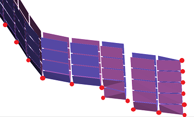
Specifying match_sideset_nodeset to explicitly define crack bottom.