original mesh
NumSplit = 1
NumSplit = 2
original mesh
NumSplit = 1
NumSplit = 2
original mesh
NumSplit = 1
NumSplit = 2
original mesh
NumSplit = 1
NumSplit = 2
Cubit 15.9 User Documentation
CUBIT provides several methods for conformally refining an existing mesh. Conformal mesh refinement does not leave hanging nodes in the mesh after refinement operations, rather conformal mesh refinement provides transition elements to the existing mesh. Both local and global mesh refinement operations are provided.
The Refine Surface and Refine Volume commands provide capability for globally refining an entire surface or volume mesh. Global refinement will only be used if the entire body is included in the command. Otherwise, the command will be interpreted as local refinement (see below.) This distinction can be important because the global refinement algorithm divides each element into fewer sub-elements than local refinement. The command syntax is:
Refine Volume <range>numsplit<int>
Refine Surface <range>numsplit<int>
The numsplit option specifies how many times to subdivide an element. A value of 1 will split every triangle and quadrilateral into four pieces, and every tetrahedron and hexahedron into eight pieces. Examples of global refinement on each element are shown below.
original mesh |
NumSplit = 1 |
NumSplit = 2 |
original mesh |
NumSplit = 1 |
NumSplit = 2 |
original mesh |
NumSplit = 1 |
NumSplit = 2 |
original mesh |
NumSplit = 1 |
NumSplit = 2 |
Figure 1. Example of uniform refinement for each of the mesh entities
CUBIT also provides methods for local refinement around geometric or mesh features. Individual elements or groups of elements can be refined in this manner using the following syntax.
Refine {Node|Edge|Tri|Face|Tet|Hex} <range>
[NumSplit<int = 1>|Size <double> [Bias <double>]]
[Depth <int>|Radius <double>] [Sizing_Function]
[Smooth]Refine {Vertex|Curve|Surface} <range>
[NumSplit<int = 1>|Size <double> [Bias <double>]]
[Depth <int>|Radius <double>] [Sizing_Function]
[Smooth]
To use these commands, first select mesh or geometric entities at which you would like to perform refinement. Refinement will be applied to all mesh entities associated with or within proximity of the entities. The all keyword may be used to uniformly refine all elements in the model
The following is a description of refinement options.
Defines the number of times the refinement operation will be applied to the elements in the refinement region. For uniform or global refinement, where all elements in the model are to be refined, A NumSplit value of 1 will split each triangle and quadrilateral into four elements, and each tetrahedron and hexahedraon into eight elements. A numsplit of 2 would result in 9 and 27 elements respectively. For uniform refinement, the total number of elements obeys the following:
In cases where only a portion of the elements are selected for refinement, the elements at the boundary between the refined and non-refined elements will be split to accommodate a transition in element size. The transition pattern will vary depending on the local features and surrounding elements. For non-uniform refinement of hexahedron, for a numsplit of 1, each element in the uniform refinement zone will be subdivided into 27 elements rather than 8. This affords greater flexibility in transitioning between the refined and unrefined elements.
The Size and Bias options are useful when a specific element size is
desired at a known location. This might be used for locally refining around
a vertex or curve. The Bias argument can be used with the Size option
to define the rate at which the element sizes will change to meet the
existing element sizes on the model. Figure 2 shows an example of using
the Size and Bias options around a vertex. Valid input values for Bias
are greater than 1.0 and represent the maximum change in element size
from one element to the next. Since refinement is a discrete operation,
the Size and Bias options can only approximate the desired input values.
This may cause apparent discontinuities in the element sizes. Using the
default smooth option can lessen this effect. It should also be noted
that the Size option is exclusive of the NumSplit option. Either NumSplit
or Size can be specified, but not both.
original mesh |
Bias=2.0 |
Bias=1.5 |
Figure 2. Example of using the Size and Bias options at a Vertex.
The Depth option permits the user to specify how many elements away from the specified entity will also be refined. Default Depth is 1. Figure 3 shows an example of using the depth option when refining at a node.
original mesh |
Depth=0 |
Depth=1 |
Figure 3. Example of using the Depth option at a node to control how far from the node to propagate the refinement.
Instead of specifying the number of elements to describe how far to propagate the refinement, a real Radius may be entered. The effects of the Radius are similar to that shown in Figure 3, except that the elements whose centroid fall within the specified Radius will be refined. Transition elements are inserted outside of this region to transition to the existing elements.
Refinement may also be controlled by a sizing function. CUBIT uses sizing functions to control the local density of a mesh. Various options for setting up a sizing function are provided, including importing scalar field data from an exodus file. In order to use this option, a sizing function must first be specified on the surface or volume on which the refinement will be applied. See Adaptive Meshing for a description of how to define a sizing function.
The default mode for refinement operations is to NOT perform smoothing after splitting the elements. In many cases, it may be necessary to perform smoothing on the model to improve quality. The smooth option provides this capability.
Controlling Regularity of Triangle Refinement
The default behavior of triangle refinement is to attempt to maximize element quality using the basic one->four template. This can sometimes result in an irregular pattern, where one or more edges are swapped. To enforce regularity of the triangle refinement pattern, regardless of quality, the folowing setting may be used.
Set Triangle Refine Regular {on|OFF}
Several tools for refining a hexahedral mesh using sheet insertion and deletion are available in CUBIT.
The following commands offer additional controls on refinement with respect to one or more geometric features of the model.
An existing hexahedral mesh can be refined at a geometric feature using the following command:
Refine Mesh Volume <id> Feature {Surface | Curve | Vertex | Node} <id_range> Interval <integer>
This command refines the mesh around a given feature by adding sheets of hexes. These sheets can be generalized as planes for surfaces, cylinders for curves, and spheres for vertices. The interval keyword specifies the number of intervals away from the feature to insert the new sheet of hexes. For this command a single sheet of hexes is inserted into the hexahedral mesh.
Figure 4 shows an example of this command where the feature at which refinement is to be performed is a curve. In this case the interval chosen was, 2. This indicated that the elements 2 intervals away from the curve would be refined.
Figure 4. Example of Refinement at a curve
Hexahedral meshes can be refined from a specific node and along a propagated path using the following command
Refine Mesh Start Node <id> Direction Edge <id> End Node <id> [Smooth]
Figure 5 shows a swept mesh and its cross section. The cross section view on the left shows a path that has been propagated through the mesh between the start node and end node. This path is then projected along a chain of edges in the direction given by the direction edge as shown in Figure 5. The start node and end node must be on the same sweep layer. This refinement procedure also requires the volume's meshing scheme to be set to sweep. If the smooth keyword is given the mesh will be smoothed after the refinement step is complete.
Figure 5. Refining a Mesh Along a Path
The following command can be used to refine the elements in one or more hex sheets:
The node and edge keywords are used to define the hex sheet(s) to be refined. If the node option is chosen, only one node pair can be entered (see Figure 6). If the edge option is chosen, one or more edges can be entered (see Figure 7).Refine Mesh Sheet [Intersect] { Node <id_1> <id_2> | Edge <id_range> } { Factor <double> | Greater_than <size> } [Smooth] [in volume <id_range> [depth <num_layers]]
Figure 6. Refine mesh sheet node 796 782 greater_than 6
Figure 7. Refine mesh sheet edge 1584 1564 1533 1502 1471 greater_than 6
The factor and greater_than keywords are used to specify the refinement criteria for the selected hex sheet(s). If the factor keyword is used, the length of the smallest edge in the hex sheet is determined and any edge in the hex sheet with a length greater than the smallest length multiplied by the factor is refined. If the greater_than keyword is used, any edge in the hex sheet with a length greater than the specified size is refined.
The intersect keyword is optional. It is used to more easily define multiple hex sheets to be refined. If the intersect keyword is entered, the node and edge keywords are used to define a chord rather than a sheet (a chord is the two-dimensional equivalent of the three-dimensional sheet). The chord will be limited to the surface(s) associated with the nodes or edge entered, and all sheets intersecting the chord will be selected for refinement (see Figure 8). When the node keyword is used with the intersect option, the nodes must define an edge on the surface of the mesh.
Figure 8. Refine mesh sheet intersect edge 1499 greater_than 6
The smooth keyword is also optional. When the smooth keyword is entered, the elements that have been refined are smoothed in an attempt to improve element quality. Figure 9 shows the same command as Figure 8 with the addition of the smooth keyword. Smoothing may or may not be beneficial, depending on the situation.
Figure 9. Refine mesh sheet intersect edge 1499 greater_than 6 smooth
Mesh sheet
refinement can also be used to refine a mesh in a particular direction. This
can help control anisotropy. The following command can be used
as a short cut for specifying what sheets should be used in refinement.
Refine Volumes <id_range> using {Plane <options> | Surface <id_range> | Curve <id_range> } [ Depth <num_layers> ] [ Smooth ]
The volumes specified indicate which hexes can be refined. A transition layer will be made out of hexes surrounding the indicated volumes. If the depth option is used, additional layers of hexes around the specified volumes will be included in the refinement region. Behind the using option, if the plane option is employed, all the edges in the volume which are parallel to the plane (to a small tolerance) are used to specify the sheets to refine. If the surface or curve option is employed instead, all the edges in the surfaces or curves will be used.
For example, Figure 10 and 11 shows directional refinement using the plane option. The command used to convert the mesh in Figure 10 to Figure 11 is:
refine vol 2 using plane xplane depth 1

Figure 10. Starting mesh
Figure 11. Directional result of refinement resulting from using the plane option on the refinement command.
Directional refinement can be used iteratively to reduce or create anisotropy of any level. This is done by applying the direction refinement command iteratively. A second iteration of directional refinement can be applied by issuing the same command again. To improve element quality, however, it is often recommended to perform refinement parallel to the plane before subsequent iterations. For example, taking the mesh in Figure 11 as input, the following commands will generate the mesh in Figure 12.
refine mesh sheet edge ( at 4.5 5 5 ordinal 1 ) factor 0
refine vol 2 using plane xplane depth 1
Figure 12. A 2nd iteration of direction refinement is applied.
Since refinement of hex meshes generally occurs by inserting hex sheets, tools have been provided to draw a specified sheet or group of sheets.
This command draws a sheet of hexes that is defined by the edge or node pair.
Draw Sheet {Edge <id> |Node <id_1> <id_2>}[Mesh [List]] [Color <color_name>] [Gradient]
The following command draws the three sheets that intersect to define the given hex. These sheets are drawn green, yellow, and red. To draw a specific sheet, list its color in the command.
Draw Sheet Hex <id> [Green][Yellow][Red][Mesh [List]] [Gradient]
The 'gradient' keyword for both commands draws the sheet in gradient shading according to the distance between opposite hex faces that are parallel to the sheet.
The 'mesh' keyword will draw the hexes in the hex sheet. If the 'list' keyword is also given, the ids of the hexes in the sheet will be listed.
Local refinement of tets, triangles, and edges is available by refining individual entities or by refining to guarantee a user-specified number of tests through the thickness:
Local refinement of tets, triangles, and edges is available. When refining triangles a node is inserted at the enter of the triangle and three new triangles are connected to this node. The original triangle is deleted. The command to refine triangles is:
Refine Local Tri <tri_id_list>
When refining an edge, a node splits the original edge between two triangles and four new triangles are created and connected to the new node. The command to refine an edge is:
Refine Local Edge <edge_id>
When refining a tet edge, the tet edge is split by a node and then all tets attached to the original edge are split into two through a triangle that goes through the new node. All other adjacent nodes and edges are unmodified by the operation. Note that on the interior of the mesh tet edges are not represented explicitly so the command takes two nodes as input to define the edge. The command to refine a tet edge is:
Refine Tet_edge Node <node1_id> <node2_id>
Cubit provides a capability to guarantee a user-specified number of tets through the thickness. This functionality is intended to work on an existing tet mesh using mesh refinement. The user specifies the geometry or mesh defining the thin region and also the number of desired tets through the thickness and the refinement algorithm will run until it meets this criteria. The number of tets through the thickness in this context is interpreted as the number of mesh edges through the thickness and the algorithm will continue to do refinement until there are no mesh edge paths through the thin region that contain fewer mesh edges than the number specified by the user. The command for doing this is:
Refine min_through_thickness <val> source {surface|node|tri|nodeset|sideset|block} <id_range> target {surface|node|tri|nodeset|sideset|block} <id_range> [anisotropic] [single_iteration] [dont_fill_in_gaps]
The various options are described below.
anisotropic: When this option is specified in the command the algorithm will only attempt to refine the edges that go roughly normal to the source and target entities. This will give an anisotropic result. The meshes on the source and target will generally not be affected when this option is used. When this option is not specified the refinement algorithm will be isotropic in nature and will propagate much more. However, it will tend to have better transitioning from the refined region to the non-refined regions.
dont_fill_in_gaps: When this option is specified in the command the algorithm will NOT try to grow the regions that will be refined. When the regions are grown it helps to avoid leaving small pockets of mesh that are not refined (splotchiness). This has effect only on isotropic refinement (when the "anisotropic" option is NOT used).
single_iteration: When this option is specified in the command the algorithm will only run for one iteration even if the min_through_thickness criteria is not met.
A quality command for querying the minimum number of tets through the thickness is found here.
Below is an example using the following commands:
refine min_through_thickness 4 source surf 1 target surf 2 anisotropic
refine min_through_thickness 4 source surf 7 target surf 13 3 14 anisotropic
Surfaces 1 and 2 are the two surfaces on opposite sides of the thin region in the green volume and surfaces 7 13 3 14 are the surfaces on opposite sides of the thin region in the yellow volume.
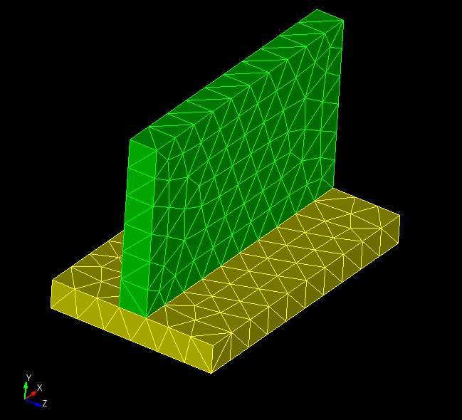
Figure 13. Before N through the thickness refinement.
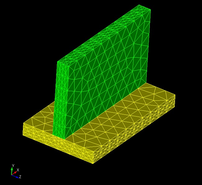
Figure 14. After N through the thickness refinement.
Global mesh refinement can be used to increase global mesh density with a single command. If an extremely large mesh is desired, one approach is to generate a coarse mesh with the desired relative mesh gradations, and then perform global mesh refinement to scale the number of elements up across the model. Depending on the amount of refinement requested, this can exceed the memory limits of Cubit running on a single processor. Global parallel mesh refinement allows refinement to go beyond the memory limits of a single processor. The resulting mesh size is only limited by the number of processors you have available to perform the refinement. The command syntax is:
Refine Parallel [Fileroot <'root filename'>] [Overwrite] [No_geom] [No_execute] [Processors <int>] [Numsplit <int>] [Version <'Sierra version'>]
This command causes Cubit to write two files to disk. First, Cubit writes an Exodus file named <root filename>.in.e which contains the mesh elements in the current Cubit session. Second, Cubit writes an OpenNURBS 3dm file http://www.opennurbs.org. named .3dm, which contains a definition of the geometry from the current Cubit Session. The Fileroot argument specifies the full path and root of the files that will be written. Additional blocks are written to the Exodus file to correspond to the geometry entities in the 3dm file. The Overwrite argument specifies if existing files on disk with the same names should be overwritten or not.
When the mesh is refined in STK_Adapt, the new nodes created during refinement will be projected to the geometry definitions from the OpenNURBS file. If the No_geom argument is specified, only the Exodus file is written, and new nodes will be placed by evaluating the shape functions of the elements being evaluated.
The exported Exodus and OpenNURBS files are prepared specifically for input into the Sierra STK_Adapt program. By default, Cubit spawns STK_Adapt in the background after exporting the files. If the No_execute argument is specified, the Cubit command exports the files, but does not spawn STK_Adapt. The user can then move those files to a large parallel machine to perform the STK_Adapt refinement.
If No_execute is not specified, then Cubit will spawn Sierra STK_Adapt in the background to perform the refinement. The Processors argument specifies the number of processors to use for the STK_Adapt run. The Numsplit argument specifies how many times the global refinement should be performed. If Numsplit = 1, then each element edge is split into 2 sub-edges. If Numsplit = 2, then each element is split into 4 sub-edges, etc. The optional Version argument allows the user to specify which version of STK_Adapt should be run. Possible values for Version include "head", "4.22.0", etc.
Refine parallel command creates groups to visualize the association between mesh entities (edge, tri, and quads ) and geometric entities (curves & surfaces). There are three types of groups that exist for each mesh entity type edge, tri, and quad. First group contains unique 1-1 map between mesh entity and geometric entity. Note that issuing "Debug 212" command before calling the refine parallel command, will create separate group for each geometric entity containing unique mesh entities. Next group contains mesh entities that point to multiple geometric entities. And the final group contains mesh entities not associated with any geometric entity.
After the Refine Parallel command finishes, the mesh in Cubit does not change, normally because the resulting mesh would be too big to store in Cubit on a single processor. Instead, the refined mesh is written to disk in a series of Exodus files, one per processor, using the Fileroot argument as the root of the Exodus file names. For example, if Fileroot is "somemesh" and Processors is 8, STK_Adapt will write out eight Exodus files named somemesh.e.8.0, somemesh.e.8.1, …, somemesh.e.8.7. These files can be kept distributed for an analysis run, or united using the Sierra EPU command. In this example, Cubit would have written out a file called somemesh.in.e, which contains all of the sideset, nodeset, and block definitions defined in the Cubit session. All of these sidesets, nodesets and blocks are transferred to the refined exodus files (somemesh.e.8.0, etc.) for use in the subsequent analysis. The somemesh.e.* files will also contain several other blocks which correspond to geometric entities defined in somemesh.3dm to enable the mesh to be refined to the CAD geometry, and should be ignored by downstream applications.
Sierra STK_Adapt must be in the PATH on the computer Cubit is running on. If Sierra STK_Adapt cannot be found, Cubit returns an error and no refinement is performed. Information on how to download and build Sierra STK_Adapt can be found at http://trilinos.sandia.gov/packages/stk/.
The Uniform Mesh Refinement (UMR) tool refines a mesh stored in the Exodus format uniformly, splitting every element in the mesh into a number of sub-elements, and writes the fine mesh to a new Exodus file. The resulting elements have roughly half the edge length of the original mesh. The algorithm uses an efficient streaming pipeline with low memory requirements. On recent CPUs with an SSD (solid state drive), it will write a mesh up to 4 billion elements or nodes in only a few minutes, and millions of elements or nodes in seconds or less.
In the alpha release of UMR, only blocks and sidesets of tetrahedra (4 node) and triangles (3 node) are supported. No projection of new nodes to geometry or smoothing is performed. Each TET element results in 8 new TET elements, each TRI results in 4 new TRI elements. Resulting blocks and sidesets in the output mesh will have the same IDs as the input mesh.
In its current form, UMR is run as an executable available on the LAN. It has the following options as displayed with the '-h' option:
Usage: ./build/extra/extra [OPTIONS] [INPUT] [OUTPUT]
| Positionals | |
| INPUT FILE | Input mesh file (coarse mesh). |
| OUTPUT FILE | Output mesh file (refined mesh). |
| Options: | |
| -h,--help | Print this help message and exit |
| -g,--geometry FILE | Snap boundary to geometry given in STEP format |
| -b,--boundary | Output the boundary mesh as OBJ file |
| -v,--verbose N:INT in [0-3] | Write increasingly more output (default =1) |
| -q,--quiet | Suppress output (same as --verbose=0) |
| -V,--version | Prints version information |
Project home page: https://cee-gitlab.sandia.gov/meshing/extra