Cubit 15.9 User Documentation
Currently, CUBIT can create volumes:
Sweeping of planar surfaces, belonging either to two- or three-dimensional bodies, is allowed, and some non-planar faces can be swept successfully, although not all are supported at this time. The following methods for generating volumes are described:
There are five forms of the sweep command; the syntax and details for each are given below. Common options for first four forms are:
draft_angle: This parameter specifies the angle at which the lateral faces of the swept solid will be inclined to the sweep direction. It can also be described as the angle at which the profile expands or contracts as it is swept. The default value is 0.0.
draft_type: This parameter is an ACIS-related parameter and specifies what should be done to the corners of the swept solid when a non-zero draft angle is specified. A value of 0 is the default value and implies an extended treatment of the corners. A value of 1 is also valid and implies a rounded (blended) treatment of the corners.
anchor_entity: The default behavior for the sweep command is to move the source surface along a path to create a new 3D solid. The anchor_entity option instructs the sweep to leave the source surface in its original location.
include_mesh: This option will sweep the source surface and existing mesh into a meshed 3D solid. The mesh size is automatically computed using the Default auto interval specification.
The sweep operations have been designed to produce valid solids of positive volume, even though the underlying solid modeling kernel library that actually executes the operation, ACIS, allows the generation of solids of negative volume (i.e., voids) using a sweep.
1. Sweep Surface Along Vector: Sweeps a surface a specified distance along a specified vector. Specifying the distance of the sweep is optional; if this parameter is not provided, the face is swept a distance equal to the length of the specified vector. The include_mesh option will create a volumetric mesh if the surface is already meshed as shown below. The keep option will keep the original surface while creating the volume.
Sweep Surface {<surface_id_range>} Vector <x_vector y_vector z_vector> [Distance <distance_value>] [switchside] [Draft_angle <degrees>] [Draft_type <0|1>][rigid][anchor_entity][include_mesh] [keep] [merge]
Surface mesh swept along a vector
2. Sweep Surface About Axis: Sweeps a surface about a specified vector or axis through a specified angle. The axis of revolution is specified using either a starting point and a vector, or by a coordinate axis. This axis must lie in the plane of the surfaces being swept. The steps parameter defaults to a value of 0 which creates a circular sweep path. If a positive, non-zero value (say, n) is specified, then the sweep path consists of a series of n linear segments, each subtending an angle of [( sweep_angle ) / ( steps-1 )] at the axis of revolution. The include_mesh option will create a volumetric mesh if the surface is already meshed as shown below. The keep option will keep the original surface while creating the volume.
Sweep Surface {<surface_id_range>} Axis {<xpoint ypoint zpoint xvector yvector zvector>|Xaxis|Yaxis|Zaxis} Angle <degrees> [switchside] [Steps <number_of_sweep_steps>] [Draft_angle <degrees>] [Draft_type <0|1>][rigid][anchor_entity][include_mesh] [keep] [merge]

Surface swept around an axis of 50 degree angle
![]() Specifying
multiple surfaces that belong to the same body will not work as expected,
as ACIS performs the sweep operation in place. Hence, if a range of surfaces
is provided, they ought to each belong to different bodies.
Specifying
multiple surfaces that belong to the same body will not work as expected,
as ACIS performs the sweep operation in place. Hence, if a range of surfaces
is provided, they ought to each belong to different bodies.
3. Sweep Surface Along Curve: This command allows the user to sweep a planar surface along a curve:
Sweep Surface <surface_id_range> Along Curve <curve_id> [Draft_angle <degrees>] [Draft_type <0 | 1 | 2>][rigid][anchor_entity][include_mesh] [keep] [individual] [merge]
One of the ends of the curve must fall in the plane of the surface and the curve cannot be tangential to the surface. The relationship between the surface orientation and the guide curve is maintained through out the sweep. If the "rigid" option is specified the orientation of the surface is kept static throughout the sweep. Sweep along curve also supports an additional draft type "2" which implies a "natural" extension of the corners from their curves.
The include_mesh option will create a volumetric mesh if the surface is already meshed as shown below. The keep option will keep the original surface while creating the volume.
Volume generated by sweeping a surface along a reference curve
4. Sweep Surface Perpendicular: This command allows the user to sweep a planar surface perpendicular to the surface:
Sweep Surface <surface_id_range> Perpendicular Distance <distance> [Switchside] [Draft_angle <degrees>] [Draft_type <integer>][anchor_entity][include_mesh] [keep] [merge]
The sweeping plane must be planar in order to determine the sweep direction. The switchside option will reverse the direction of the sweep.

The original surface is retained with the 'keep' option. A new volume is created by sweeping the surface along the surface normal.
The include_mesh option will create a volumetric mesh if the surface is already meshed as shown below. The keep option will keep the original surface while creating the volume.
5. Sweep Surface to a Volume: This command allows users to sweep a surface to a volume.
Sweep Surface <surface_id_range> Target {Volume|Body} <id> [Direction {options}] [Plane {options}]
The direction keyword can be used to control the direction of sweep. Without it, Cubit will determine the sweep direction (usually normal to the sweeping surface). The plane option can be used to define a stopping plane.
6. Offset: The following command creates a body offset from another body or set of surfaces at the specified distance. The new surfaces are extended or trimmed appropriately. A positive distance results in a larger body; a negative distance in a smaller body.
Using the second form of the command, the sheet body can be created from a list of surfaces, and the surfaces may offset by different distances. This command currently requires the original surfaces to be on solid bodies.Create Body Offset [From] Body <id_range> Distance <value>
Create Sheet Offset From Surface <id_list> Offset <val> [Surface <id_list> Offset <val>] [Surface <id_list> Offset <val> ...] [Preview]
This option is also available for limited cases for facet-based surfaces.
7. Sheet Extended from Surface: The following command creates a body offset from another body or set of surfaces at the specified distance. The new surfaces are extended or trimmed appropriately. A positive distance results in a larger body; a negative distance in a smaller body.
Create Sheet Extended From Surface <id_list> [Intersecting <entity_list>] [Extended {Percentage|Absolute} <val>] [Preview]
This command allows multiple surfaces to be extended at the same time. Optionally, you can give a list of bodies to intersect for this calculation. You can also extend the size of the surface by either a percentage distance or an absolute distance of the minimum area size. The plane can be previewed with the preview option. Figure 1 shows a set of surfaces being created using the extended absolute option.
Figure 1. Sheet created from extending multiple surfaces
8. Sweep Curve About Axis: Sweeps a curve or set of curves about a given axis through a specified angle. The axis is specified the same as in the Sweep Surface About Axis command. The steps, draft_angle, and draft_type options are the same as are described above. To create the solid, the make_solid option must be specified, otherwise a surface will be created, rather than a solid. If the rigid option is specified, then the curve or set of curves will remain oriented as originally oriented, rather than rotating about the axis.
Sweep Curve <curve_id_range> {Axis <xpoint ypoint zpoint xvector yvector zvector>|Xaxis|Yaxis|Zaxis} Angle <degrees> [Steps <Number_of_sweep_steps>] [Draft_angle <degrees>] [Draft_type <integer>] [Make_solid] [Rigid]
9. Stitch Surfaces Together: A body can be created from various surfaces that form a closed volume with command below. The geometry must be ACIS-type geometry (i.e. imported from IGES, STEP or fastq files) This option is also available for limited cases for facet-based surfaces.
Create {Body|Volume} Surface <surface_id_range> [HEAL|Noheal] [Keep] [Sheet]
The heal option will attempt to close small gaps in the surface; the noheal option disables this behavior. The keep option preserves the original surfaces.
All of the surfaces must form a closed water-tight volume for this command to succeed unless the sheet option is specified.
The sheet option allows for the creation of an open body. If the set of surfaces form a closed volume a sheet body is created instead of a volume.
In situations where the boundaries are not exactly within tolerance, the following command may be more effective:
Stitch {Body|Volume} <id_range>


 [tolerance <value>] [no_tighten_gaps]
10. Loft Surfaces Together: A body can be "lofted" between two surfaces to form a new body. Surfaces from solid bodies and sheet bodies may be used to create a loft body. In order to create the loft body, two surfaces coincident to the input surfaces are created. The loft body is extruded along the shortest path between the corresponding vertices that define the shapes of the two surfaces. If guide curves are used the loft body is extruded along the guide curves. This new body is solid. The surfaces used to create the loft body are unchanged.
Create {Body|Volume} Loft Surface <ids> [guide curve <id_list> [global_guides]] [Takeoff_factors <one value per surface in order>=.001] [Takeoff_vector Surface <id> {direction options}] [match vertex <ids>] [closed] [preview] [show_matching_curves]
Note:Source surface ids must be specified in lofting order.
Go to Location, Direction, and Axis Specification to see the direction command description.
The following options are available for lofting:
Lofting can be used to split a body in order to create a more structured mesh. Figure 2 below shows a single volume swept from a large paved surface. Figure 3 shows this same volume after surfaces defined on the source and target surfaces have been used to create a loft body. This original body was chopped with the loft body. The resulting two bodies were merged. The yellow volume was swept as the volume in Figure 2 was but the purple volume was submapped, producing a much more structured mesh overall.
Figure 2. Mesh before loft. Single swept volume with a large paved face.
Figure 3. Mesh after loft. The yellow volume is paved and the purple volume is submapped.
11. Thicken Surfaces: A surface body can be thickened to create a volume body. The surface can be thickened in both directions using the "both" keyword, thickened in the direction of surface normal using a positive depth, or thickened in the opposite direction using a negative depth. To thicken multiple surfaces, all surface normals must be consistent.
Thicken [Volume|BODY] <id> Depth <depth> [Both]
12. Sweeping a Surface to a Plane: Sweeps a surface normal to a plane and towards the plane until the swept surface reaches the plane. See plane options for ways to describe a plane.
Sweep surface <id> target plane <options>
13. Sweep Surface along a Direction: Sweep a surface along a direction to create a volume. See direction options for ways to specify a direction.
Sweep Surface <surface_id_range> Direction (options) [switchside] [draft_angle <degrees>] [draft_type <integer>] [rigid] [anchor_entity] [include_mesh] [keep] [merge]
Surface extruded along -X direction without 'include_mesh' option
14. Sweep Surface along Helix: Sweep a surface along a helix, where the helix is defined by an axis, thread_distance (distance between turns in axis direction), axis, and handedness (right_handed or left_handed.
Sweep {Surface|Curve} <id_range> Helix {axis <xpoint ypoint zpoint xvector yvector zvector> | xaxis | yaxis | zaxis} thread_distance <val> angle <val> [RIGHT_HANDED|left_handed] [anchor_entity] [include_mesh] [keep] [merge]
*** Specifying multiple Surfaces that belong to the same Body can cause the creation of invalid Bodies and is discouraged. ***
axis = axis about which to create the sweep
thread_distance = distance between each 360 degree segment of the helix
angle = number of degrees in rotation of the helix
handedness = right-handed or left- handed threads
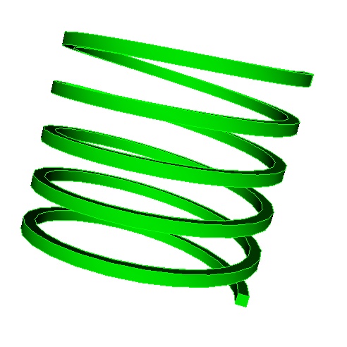
Helical Sweep