Cubit 15.9 User Documentation
By default, the scene is viewed as a smoothshaded model. That is, only curves and edges are drawn, and surfaces are transparent. Surfaces can be drawn differently by changing the graphics mode:
Graphics Mode {Wireframe | Hiddenline | Smoothshade | Transparent } [Geometry | Mesh | Highlight]
The GUI tool bar buttons for manipulating the graphics modes are as follows:
![]()
Examples and a brief description of each mode are shown below
 |
WireFrame - Surfaces are invisible. (This mode can also be accessed by typing 'wireframe' at the command prompt.) |
 |
HiddenLine - Surfaces are not drawn, but they obscure what is behind them, giving a more realistic representation of the view. (This mode can also be accessed by typing 'hiddenline' at the command prompt.) |
 |
SmoothShade - Surfaces are filled and shaded. Shaded colors are interpolated across the entire surface using the graphics lighting model. This produces the most realistic results. (This mode can also be accessed by typing 'shaded' at the command prompt.) |
| Transparent - Renders surfaces as semi-transparent shaded images, allowing objects to shine-through from behind. Is not supported on all platforms, and generally requires advanced graphics hardware. (This mode can also be accessed by typing 'transparent' at the command prompt.) |
This determines what pattern is used to draw lines behind surfaces (e.g. dotted, dashed, etc.; click here for a list of valid line patterns).
There is another option that is similar to a graphics mode, set with the command
Graphics Use Facets [On|Off]
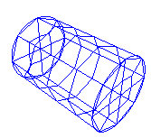
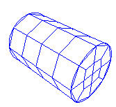
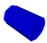
This command determines how shaded and filled surfaces are drawn when they are meshed. If Graphics Use Facets is on, the mesh facets (element faces) are used to render the model. This is particularly helpful for curved surfaces which may cut through some of the mesh faces. A comparison of graphics facets on and off is shown below.
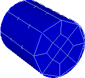
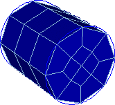
Figure 1. A meshed cylinder shown with graphics facets off (left) and graphics facets on (right); note how geometry facets on the curved surface obscure mesh edges when facets are off.
Composite surfaces are surfaces that have been joined together using virtual geometry. By default, the underlying surfaces are marked with dashed lines. To toggle this setting so that underlying surfaces are not shown, use the following command:
Graphics Composite {On|Off}
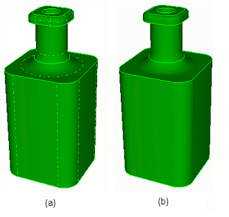
Figure 2. A part shown with (a) composite surfaces displayed (b) composite surfaces not displayed
The GUI tool bar button for toggling the display of graphics composites is as follows:
![]()