Cubit 15.8 User Documentation
Applies to: Volumes
Summary: Produces an extruded hexahedral mesh for 2.5D volumes.
Syntax:
Volume <range> Scheme Sweep [Source [Surface] <range>] [Target [Surface] <range>]
[Propagate bias]
[Sweep smooth {auto | smart affine | linear | residual | winslow} ]
[Sweep transform {LEAST SQUARES | Translate}] [Autosmooth target {ON|off} ]Volume <range> Scheme Sweep Vector <xval yval zval>
Volume <range> autosmooth target [off|ON]
fixed imprints [on|OFF]
smart smooth [ON|off] tolerance <val 0.0 to 1.0=0.2>
nlayers <val >=0=5>
Related Commands:
Set Multisweep [On|Off]
Multisweep Smoothing {ON|Off}
Multisweep Volume <range> Remove
Volume <range> Redistribute Nodes {ON|off}
[Set] Legacy Sweeper {On|Off}
Discussion:
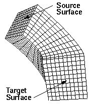
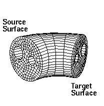
The sweep algorithm can sweep general 2.5D geometries and can also do pure translation or rotations. A 2.5D geometry is characterized by source and target surfaces which are topologically similar. The hexahedral mesh is swept (extruded) between source and target along a single logical axis. Bounding the swept hexahedra between source and target surfaces, are the linking surfaces. Figures 1 and 2 show examples of source, target and linking surfaces.
Command Options: The user can specify the source and target surfaces. The user can also specify a geometric vector approximating the sweep direction, and let CUBIT determine the source and target surfaces. The user can specify just the source surfaces, and let cubit guess the target, or "scheme auto" can also be used.


Figure 1. Sweep Volume Meshing
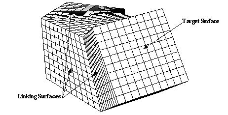
Figure 2. Multiple Linking Surface Volume Meshing with Scheme Sweep
In general, the procedure for using the sweep scheme is to first mesh the source surfaces. Any surface meshing scheme may be employed. Figure 1 displays swept meshes involving mapped and paved source surfaces. Linking surfaces must have either mapping or submapping schemes applied. The sweep algorithm can also handle multiple surfaces linking the source surface and the target surfaces. An example of this is shown in Figure 2. Note that for the multiple- linking-surface meshing case, the interval requirement is that the total number of intervals along each multiple edge path from the source surface to the target surface must be the same for each path. Once the appropriate mesh is applied to the source surface and intervals assigned, the mesh command may be issued.
In many cases auto-scheme selection can simplify this process by recognizing sweepable geometries and automatically select source and target surfaces. If the source and target surfaces are not specified, CUBIT attempts to automatically select them. CUBIT also automatically sets curve and vertex types in an attempt to make the mesh of the linking surfaces lead from a source surface to a target surface. These automatic selections may occasionally fail, in which case the user must manually select the source/target surfaces, or some of the curve and vertex types. After making some of these changes, the user should again set the volume scheme to sweep and attempt to mesh. In some cases of 1-1 sweeps, the source and target are swapped. Precedence for which surface to use as the source is {meshed, merged, specified as source}. If the user wants to avoid swaps and enforce that a particular surface is the source, then they can mesh that prior to sweeping.
Occasionally the user must also adjust intervals along curves, in addition to the usual surface interval matching requirements. For a given pair of source/target surfaces, there must be the same number of hexahedral layers between them regardless of the path taken. This constrains the number of edges along curves of linking surfaces. For example, in Figure 1 right, the number of intervals through the holes must be the same as along the outer shell.
Propagate bias Option: The propagate bias option attempts to preserve the source bias by propagating bias mesh schemes from the curves of the source surface to the curves of the target surface. It also propagates bias from one linking curve to all other linking curves.
Sweep transform Option: Swept meshes are created by projecting points between the source and target surfaces using affine transformations and then connecting them to form hexahedra. The method used to calculate the affine transformations is set using the sweep transform option.
Least squares: If the least squares option is selected then affine transformations between the source and target are calculated using a least squares method.
translate: If the translate option is selected then a simple translate affine transformation is calculated based upon the centroid of the source and target.
Sweep smooth Option: Note: This option is available only in Legacy mode. The command 'set legacy sweeper on|off controls the mode. Legacy mode is OFF by default.
To ensure adequate mesh quality, optional smoothing schemes are available to reposition the interior nodes. The sweep tool permits five types of smoothing that are set with the following command prior to meshing a volume whose mesh scheme is sweep:
Linear: If this option is selected, no layer smoothing is performed. The node positions are determined strictly by the affine transformation from the previous layer. Good quality swept meshes can be constructed using “linear” provided the volume geometry and meshed linking surfaces permit the volume mesh to be created by a translation, scaling, and/or rotation of the source mesh. Volumes for which this is nearly true may also produce acceptable quality with “linear”. As one would expect, this option generates swept meshes more quickly than the other sweep smooth options. This option is rarely needed since the next option produces better results with little time penalty.
Smart affine: The “smart affine” option does minimal smoothing of the interior nodes. Affine transformations are used to project the source and target surfaces to the middle surface of the volume. The position of the middle surface nodes is the average of the projected nodes from the source and target surfaces. The error in projecting from source and target is computed, and this error is linearly distributed back to the source and target.
Residual: The “residual” method is often used for meshing volumes that cannot be swept with the “smart linear” method. It tends to produce better quality meshes than the “smart linear” method while running faster than the Winslow-based smoother. The sweeping algorithm uses an affine transformation to calculate the interior nodes’ positions, but the mesh on the linking surface determines the positions of the nodes on the boundary of the layer. For the “residual” method, CUBIT calculates corrective adjustments for interior nodes using the “residuals” from boundary nodes. The “residual” is defined as the distance between the boundary node’s position (as determined by the surface mesh) and the boundary node’s ideal position (as determined by the affine transformation of the previous layer). Cubit computes the residual forward from the source and backward from the target to get best the possible node position.
Winslow: Smooth scheme “winslow” smooths each layer using a weighted, elliptic smoother. The weights are computed from the source mesh; they help maintain any biased spacing that occurs on the source mesh. For example, one might want to use the “winslow” option if the source was a biased mesh that was created using scheme circle. The biasing of the outer elements of the source mesh may be destroyed if one of the other smooth options is used. The interior nodes are initially place using the residual method.
AUTO: This is the default for the sweep smooth option. “auto” causes the Sweeper to automatically choose between “smart affine” and “residual.” Auto will choose “off” if the layer needs little or no smoothing or “residual” if it needs smoothing. Scheme “auto” does not guarantee that no negative Jacobians are produced. This option produces acceptable results in most cases. If it fails to produce a quality mesh, then choose one of the other sweep smooth options.If none of these smooth schemes result in adequate mesh quality, one can consider trying one of the volume smoothing schemes such as condition number or mean ratio.
Autosmooth target Option and Command
During sweeping, a quad mesh is placed on each source surface. Then the collection of nodes & quads from all the source surfaces is projected onto the target surface. The autosmooth target command or sweep command options control the placement of the nodes onto the target surface.
Volume <range> autosmooth target [off|ON]
fixed imprints [on|OFF]
smart smooth [ON|off] tolerance <val 0.0 to 1.0=0.2>
nlayers <val >=0=5>
Issuing the command “Volume <id> autosmooth target off”, or using these options in the sweep command, will project the source nodes onto the target without any subsequent smoothing to improve quality. The result is that the relative placement of the nodes on the target will be as close to identical as possible to the relative placement of the node on the sources. This should be used when sweeping models that are very thin, and smoothing of the target could result in significant skew introduced in the thin layers in the sweep. Axisymmetric models might also want to turn OFF the autosmooth target so that the nodes are identically placed on the symmetry plane surfaces.
Issuing the command “Volume <id> autosmooth target on”, or using it as an option in the sweep command, will call a surface smoother after the initial projection of the nodes onto the target in order to improve surface element quality. This smoothing does not consider hex element quality, only quality of the target surface mesh. This command will smooth all nodes on the target surface. Adding the “fixed imprint on” keyword onto the command will cause the target nodes which are projections of source nodes on source curves and vertices to remain fixed during smoothing. Only target nodes, which are projections of source surface nodes will be smoothed. The “smart smooth on” option provides further control to the user. If “smart smooth” is turned on, target surface smoothing will only move nodes which are within “nlayers” of a target surface quad element that has a scaled Jacobian quality measure less than the specified “tolerance” value.
While the basic sweeping algorithm requires a single target surface, the sweeping algorithm can also handle multiple target surfaces. The multisweep algorithm works by recognizing possible mesh and topology conflicts between the source and target surfaces and works to resolve these conflicts through the use of the virtual geometry capabilities in CUBIT. Figure 4 shows some examples of volumes which have been meshed with the multisweep algorithm.
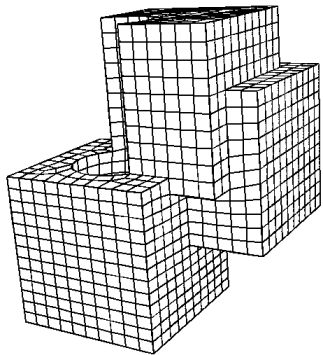
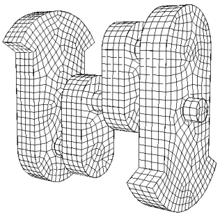
Figure 4. Examples of Multisweep meshes.
Linear: If this option is active and/or target surfaces are omitted from the scheme setting command, CUBIT will determine source and target surfaces (See Automatic Scheme Selection). Sweeping can be further automated using the "sweep groups" command.
- Limitations: Not all geometries are sweepable. Even some that appear sweepable may not be, depending on the linking surface meshes. Highly curved source and target surfaces may not be meshable with the current sweep algorithm.
Grouping Sweepable Volumes
Swept meshing relies on the constraint that the source and target meshes are topologically identical or the target surface is unmeshed. This results in there being dependencies between swept volumes connected through non-manifold surfaces; these dependencies must be satisfied before the group of volumes can be meshed successfully. For example, if the model was a series of connected cylinders, the proper way to mesh the model would be to sweep each volume starting at the top (or bottom) and continuing through each successive connected volume.
With larger models and with models that contain volumes that require many source surfaces, the process of determining the correct sweeping ordering becomes tedious. The sweep grouping capability computes these dependencies and puts the volumes into groups, in an order which represents those dependencies. The volumes are meshed in the correct order when the resulting group is meshed.
To compute the sweep dependencies, use the command:
Group Sweep Volumes
This will create a group named "sweep_groups", which can then be meshed using the command:
Mesh sweep_groups
In some automated meshing systems, the source and target surfaces are named using a naming pattern. For example, all source surfaces might be given names "xxx.source" and all target surfaces might be named "xxx.target". This allows the automated setting of the sweep direction based on predetermined names rather than ids. The following command is used to set the source and targets based on the naming pattern.
Set {Source|Target} Surface Pattern '<pattern>' [Include Volume Name]
The pattern is checked against all surfaces in the model using a simple case-sensitive substring match. All surfaces which contain that string of letters in their name will be designated as either a source or target surface, depending on which option the user specifies. For example:
br x 10
surface 1 name 'brick.top'
surface 2 name 'brick.bottom'
set source surface pattern 'top'
set target surface pattern 'bottom'
volume 1 scheme sweep
list volume 1 briefNode Redistribution
Volume <range> redistribute nodes {ON|off}
With redistribute set to ON, the boundary nodes of a mappable surface are moved until the spacing between the nodes are equivalent on the two opposing curves. In other words, the parametric values of the nodes lying on the two opposite curves are matched.
Redistribute option ON will assist in avoiding the skewness of the mapped mesh. In the below examples, the linking surfaces are meshed using mapped scheme, and with redistribute option ON, the skewness is significantly avoided (see figures (4) and (5)).
Note:
1. Redistribute option ON will affect all mapped surfaces, not just the linking surfaces of a swept volume. Even though the example below shows a swept volume, the command can be used independent of the sweeping command. That is, it can be used while meshing surface models that contain mappable surfaces.
2. If the linking surfaces of a swept mesh contain submappable surfaces, then the affect of redistribute option ON is generally not seen. The current implementation is restricted to mappable surfaces only and doesn’t handle submappable surfaces. In the future, we should be able to easily extend the redistribute option to submappable surfaces.
Figure 1 - Linking surfaces of a many-to-one sweepable solid (shown in green) is mappable
Figure 2 - Highly skewed elements on the linking mapped surface with 'redistribute nodes OFF'
Figure 3 - Quality of mesh with 'Redistribute Nodes OFF'
Figure 4 - High skew on the linking mapped surface can be avoided with 'Redistribute Nodes ON'
Figure 5 - Quality of mesh with 'Redistribute Nodes ON'