Cubit 15.8 User Documentation
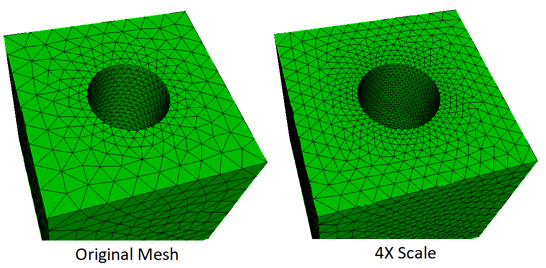
Cubit supports the scaling of hexahedra and tetrahedra meshes. Mesh Scaling allows a series of meshes to be built [typically] for solution convergence studies or other purposes. Each mesh has progressively larger or smaller elements. For example, if the input mesh has 10,000 hexahedra, scaling with a multiplier of 2.0 will result in a mesh of about 20,000 hexahedra, with approximately the same element orientation and size gradations as the original, as seen in Figure 1. Additional meshes can be built by scaling the original mesh with multipliers of 4, 6, 8, etc. Scaling by a value less than 1.0 will produce a mesh with fewer elements. Scaling by a negative value is not allowed. Convergence studies can be performed with much less computational cost than if traditional global refinement is used, because the element increase at each step of the series can be smaller.
Figure 1.
scale mesh [volume <ids>]
[multiplier <value, default=2.0>]
[minimum <value, default=1>]
[{SWEPT_BLOCKS |
legacy | maintain_structure}]
[feature_angle <value>]
[force_structured in {[volume <ids>] [surface <ids>]}]
[thin_gap_intervals <value, default=2>] [fix_all_gaps]
[max_aspect_ratio <value> in volume <ids>]
[max_feature_length <value, default=30>]
[smooth_volume {ON|off}]
Specifying a list of volumes is optional. By default, all volumes will be scaled. For Hex Mesh Scaling, the specified volumes, together with any volumes merged with them, will be scaled. Tet Mesh Scaling only scales the specified volumes, preserving the shared mesh boundary with any non-participating volumes. This approach allows individual assembly components to be scaled, without scaling the entire model.
The target number of output elements is the number of input elements times the multiplier parameter. The default value is 2.0. For example: the mesh in Figure 2a has 3025 hex elements. After scaling by 2.0, the mesh in Figure 2b has 6804 hexes. Note the locations of new nodes are projected to lie on the associated CAD geometry, if any.

Figure 2a. Input mesh of 3025 hex elements.

Figure 2b. Output mesh of
6804 hexes,
after scaling with a multiplier of 2.0.
Tetmesh scaling woks by using the original tet mesh as a background sizing mesh, with a size on each node to achieve the desired scale factor. The only command parameter relevant to tet mesh scaling is the multiplier parameter. All others are used for Hex Mesh Scaling.
Hex Mesh Scaling is more flexible than template-based global refinement methods, because it does not require that every element is refined, or refined in the same way. Instead, Hex Mesh Scaling decomposes the entire mesh into larger "blocks" of hexes, and then refines the blocks. In this way, Mesh Scaling supports increasing the element count by small multiplicative factors, e.g. 1.5, that are impossible with template based refinement. However, like template refinement, it can ensure that every location of the mesh is refined. These features can be useful for solution verification.
A traditional template-based refinement replaces each hexahedron with a 2x2x2 structured grid of hexahedra, increasing the element count by a factor of 8X. In contrast, Hex Mesh Scaling refines "blocks" of elements (not to be confused with Exodus element blocks). The block decomposition subdivides the entire mesh into structured (mapped) and swept blocks. A block may contain many elements, but is not allowed to cross geometric boundaries, boundary conditions, and loading constraints. For example, a block cannot have a curve or nodeset in its interior, nor hexes from multiple Exodus blocks. Blocks may be structured or logical sweeps. A structured block is restricted to be a grid of MxNxO hexes, so, its extent is limited by any surface nodes that do not have exactly four edges, etc. Hex Mesh Scaling remeshes the entire model conforming to the block decomposition, using the original mesh as a sizing function, multiplied by the scale factor.
The minimum parameter provides further control over the level of refinement. It is the minimum number of intervals added to each block-curve. Specifying minimum 1, which is the default, will guarantee that at least one interval is added to every element block in all 3 directions, which guarantees every part of the domain is scaled by at least a little bit. This can be "turned off" by specifying minimum 0.
The multiplier determines the target number of output hexes. There is no guarantee it will be achieved exactly. For minimum 0 and small multipliers, there is no guarantee that every block will be refined in all 3 directions. This is because the target number of elements may be reached first. This may lead to unevenly distributed refinement, with jumps in adjacent element sizes.
An uneven distribution may also result if adjacent blocks have significantly different MxNxO intervals; this is common with the legacy option. For example, for a 1x10x12 block adjacent to a 6x10x12 block, Mesh Scaling could output 2x11x13 and 7x11x13 blocks. The M value of the first block has doubled, 2/1, while the M value of the second block has only increased by 7/6. Thus, the user may observe a jump in the lengths of adjacent edges.
To coarsen a mesh, specify a multiplier less than one. For example, a multiplier of 0.9 will attempt to decrease the element count by 10%. Each block side will have its intervals decreased by the minimum value. A block must have at least one interval, so how far the mesh can be coarsened is limited by the distance between mesh irregularities, geometry, boundary condition and loading constraints.
Mesh Scaling is useful for solution verification, as it can easily generate a series of similar meshes of increasing mesh density. For best results, generate each mesh in the series by scaling the original mesh, rather than scaling the previous mesh of the series. It is suggested that each mesh uses a multiplier at least 2X larger, and a minimum at least one more, than the prior mesh. Small multipliers alone are unlikely to produce sufficient changes for solution verification. The minimum is especially useful for ensuring changes in regions that are initially coarse. A good set of (multiplier, minimum) parameters follows:
(2X, 1) (4X, 2) (8X, 3) (16X, 4), (prior *2, prior +1), etc.
A large minimum can cause quality problems and generate too many elements. For example, the minimum in the parameter series (2X, 1) (3X, 2) (4X, 3) (5X, 4) (6X, 5) (7X, 6) (8X, 7) etc. would likely be too aggressive. It would produce many more elements than the specified multiplier, potentially causing poor element quality or even mesh scaling failure. For a slowly increasing set of multipliers, a less aggressive minimum series is recommended, such as
(2X, 1) (3X, 1) (4X, 2) (5X, 2) (6X, 2) (7X, 2) (8X, 3) etc..
There are three major block decomposition variations to choose from. To understand their differences, one must first understand the two types of blocks: "structured" and "swept" blocks. A structured block is a MxNxO structured grid. A swept block is a single-source to single-target sweep of some subset of a single volume. That is, it is composed of a single surface of quad elements, projected some number of layers to form hexes.
The block decomposition options are swept_blocks (default), maintain_structure and legacy. For legacy, only structured blocks are used. For swept_blocks and maintain_structure, the decomposition constructs large swept blocks wherever logical sweeps can be identified, and structured blocks otherwise. The main difference is that swept_blocks remeshes the source surfaces of swept blocks from scratch. In contrast, maintain_structure partition each swept block into structured sub-blocks, and remeshes by selectively refining those sub-blocks. Thus swept_blocks may change the number and relative location of irregular nodes, whereas maintain_structure keeps them the same.
Typically, swept_blocks and maintain_structure provide smoother, more evenly distributed refinements compared to legacy. This is because with swept blocks, there are typically significantly fewer blocks in the decomposition. Having fewer blocks increases the likelihood that each block will receive at least some refinement before the multiplier is reached.
However, legacy and maintain_structure provide element orientations and structure closer to the original mesh than swept_blocks. This is because structured blocks maintain the irregular nodes.
Often maintain_structure provides both element orientations closer to the original mesh and a smoother, more evenly distributed refinement. Its structured blocks preserve orientations and structure. Its swept blocks provide the freedom to distribute changes, and smooth the mesh, across its structured sub-blocks.
In some cases, the user may want to use swept blocks in only some parts of the model. The original mesh may have small regions with carefully constructed meshes. Using swept_blocks can destroy these constructions, replacing them with pave-and-sweep meshes. These constructions can be preserved by specifying force_structured for the surfaces and volumes containing them.
For example, see Figures 3, 4 and 5. In Figure 3 surface 108 was meshed with great care to ensure a structured mesh around the holes, while surface 34 was meshed with paving. Since surface 108 has irregular nodes, it appears to Mesh Scaling as the source surface of a swept block. Figure 4 illustrates the resulting mesh from the command "scale mesh multi 2". Notice the structured meshes around the holes have been replaced with a standard paved mesh. Figure 5 illustrates preserving the structured holes of surface 108 while allowing surface 34 to be repaved. The command was "scale mesh multi 2 force_structured in surface 108". A different mesh would result from the command scale mesh multi 2 force_structured in volume 1 , because this would also preserve the irregular nodes in surface 34, resulting in more blocks and a less smooth mesh.

Figure 3. Input mesh. Surface 108's mesh has desired structure and irregular nodes. Surface 34 contains a paved mesh.

Figure 4. Output mesh from the command "Scale Mesh Multi 2". The mesh on surface 108 is replaced with a paved mesh.

Figure 5. Output mesh from the command "Scale Mesh Multi 2 force_structured in Surface 108". The desired features are maintained, while swept blocks are used in unimportant regions.
For the maintain_structure option, the thin_gap_intervals parameter determines how thin gaps are defined. If two disjoint curves of a surface come close together, the space between them is considered a "thin gap" if the number of intervals across that space is at most thin_gap_intervals. Mesh scaling gives high priority to adding intervals within thin gaps. By default, the position of some nodes within thin gaps are fixed to help reduce skew. The fix_all_gaps option fixes all nodes in thin gaps. Features, e.g. curves and gaps, longer than max_feature_length intervals will be split into multiple features. This results in fixing additional nodes along the feature to help reduce skew.
In general, maintain_structure should result in a smoother scaled mesh than the other algorithms, however, sometimes it can introduce some skew in the scaled elements. If skew is introduced by scaling using maintain_structure, try either increasing the thin_gap_intervals parameters, specifying fix_all_gaps, decreasing the max_feature_length parameter, or all three.
The feature_angle and max_aspect_ratio options affect the formation of swept blocks. These are alpha, experimental commands.
If smooth_volume is on, then the volume mesh is smoothed as a post-process if it has poor quality elements, and smaller minimum quality than the original mesh. By default, smooth_volume is on.