Cubit 15.8 User Documentation
The following forms of the create and merge commands operate on meshed entities only. They allow low-level editing of meshes to make minor corrections to a mostly correct mesh. They are not designed for major modifications to existing meshes. Because Cubit's display routines were not designed with these type of operations in mind, these commands may cause the current display of the affected entities to take an unexpected form. An appropriate drawing command can be used to return the display to the desired view.
The delete commands for deleting individual elements are still under development, but they may be used after setting a developer flag.
The create command uses existing mesh nodes to create new mesh entities.
Create {Hex|Tet} Node <range> [Owner Volume <id>]
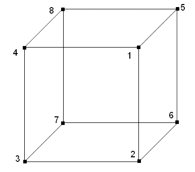
Using the nodes specified, this form of the command creates a new hex or tet that will be owned by the specified volume. For a hex, 8 nodes are required. The order in which the nodes are specified is very important. They should describe two opposing faces of the hex; the normal of the first face should point into the hex and the normal of the second face should point out of the hex. For example, to create the hex shown in Figure 1 below, the following command would be entered:
create hex node 1,2,3,4,5,6,7,8 owner volume 1

Figure 1. Node Numbering for the Create Hex command
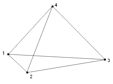
To create a tet, 4 nodes are specified. The base is specified as a tri with the normal point toward the fourth node using the right hand rule. To create the tet shown in Figure 2, the following command would be entered:
create tet node 1,2,3,4 owner volume 1

Figure 2. Node ordering for Create Tet Command
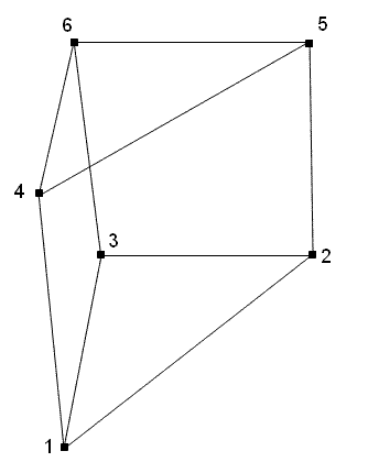
To create a wedge, 6 nodes are specified. The base is specified as a tri with the normal pointing inward using the right hand rule. To create the wedge shown in Figure 3, the following command would be entered:Create Wedge Node <range> [Owner Volume <id>]
create wedge node 1,2,3,4,5,6 owner volume 1

Figure 3. Node ordering for Create Wedge Command
Create {Face|Tri} Node <range> [Owner {Volume|Surface} <id>]
The next form of the command creates a face or tri that will be owned by the specified volume or surface. Four nodes are specified for a face, three nodes for a tri. The nodes should be specified in the order needed to produce a face or tri with the normal in the desired direction using the right hand rule.
Create Edge Node <range> [Owner {Volume|Surface|Curve} <id>]
This form of the command creates an edge that will be owned by the specified volume, surface, or curve. Two nodes must be specified; order is unimportant.
Create Node Location <x> <y> <z> Owner {Volume|Surface|Curve|Vertex} <id>
The last form of the command creates a node at the specified location that will be owned by the specified volume, surface, curve, or vertex. The location is specified by three absolute values that represent the position of the node in 3D space.
The merge node command is used to join two mesh entities one node at a time. It should be used with care because merging nodes of different meshed entities may have unpredictable results. The syntax is:
Merge Node <id1> <id2>
The merge node command replaces the node specified as id1 with the node id2. The command is equivalent to deleting node id1 and creating node id2 in the same location. The resultant merged node takes on the characteristics of the replaced node such as position and owner. This may include some or all of the higher level mesh entities related to the merged node.
Caution should be taken when using the merge node command because other commands involving the related meshed entities may not work properly following the merge.