Cubit 15.8 User Documentation
Each part and assembly has a name and an optional description. Other attributes may also be assigned, such as a material specification or a link to an entry in a PDM system. See Metadata Attributes.
The relationship between the geometric model and the assembly is determined by associating parts with volumes. A single part can be associated with any number of volumes, including zero volumes. A volume, however, can be associated with only one part.
As volumes are modified, CUBIT automatically maintains the appropriate relationships with parts. If a volume is associated with a part, and that one volume is split into multiple volumes through a webcut or some other operation, each of the resulting volumes is automatically associated with the original volume’s part. Copying a volume will also result in the new volume being associated with the same part as the original volume.
A part or assembly is identified by its assembly path. An assembly path is much like a directory path in a file system. It consists of the name of each ancestor in the assembly tree, separated by a forward slash. For example, a part named “p1” contained within the top-level assembly “a1” would be identified by the path “/a1/p1”. If the part “p2” is part of the assembly “a2”, and “a2” is a sub-assembly of “a1”, then “p2” has the path “/a1/a2/p2”.
More than one part or assembly may have the same name. To differentiate between parts or assemblies with the same name and path, each part also has an instance number. If two entities have the same name, they will not have the same instance number. For example, two parts named “p1” may be “p1 instance 1” and “p1 instance 2”.
Instance numbers may be incorporated into assembly paths by placing the instance number in angled braces after a part or assembly name. For example, “p1 instance 3” is identified in a path as “p1<3>”. Other examples of instance numbers in assembly paths include “/a1<1>/a2<1>/p1<3>” and “/a1/a2<1>/p1”. Assembly paths are always allowed to incorporate instance numbers, but are only required to include as many instance numbers as it takes to avoid ambiguity. Note that some commands do accept ambiguous paths, selecting a random entity which matches the path.
Most commands which accept assembly paths also allow the path to be followed by an “instance” command option (for example, metadata list part “/a1/p1” instance 3). The instance option always refers to the instance number of the last item in the path (p1 in the example).
Parts and assemblies can be created using the following commands:
Metadata Create {Assembly|Part} “<absolute_path>” [Instance <instance>]
If the instance option is not included, CUBIT will assign an appropriate instance number to the new entity. If the instance option IS included, an entity with the specified name and instance number must not already exist or the command will fail.
Note that the path must be absolute, identifying each ancestor of the new entity. Any ancestors of the new entity which do not already exist are automatically created.
To delete a part or an assembly, use the Metadata Remove command:
Metadata Remove {Part “<path>” | Assembly “<path>" [propagate]}
This will remove the specified part or assembly. If the propagate option is specified when removing an assembly, all contained parts and subassemblies will be removed automatically before the assembly itself is removed. Otherwise, assemblies will only be removed if they have no contents.
It is also possible to remove all parts and assemblies that have no association with geometric volumes in the model:
Metadata Clean
This can be extremely useful when importing geometry which has been simplified with metadata which has not been simplified. For example, eMatrix currently writes out the full assembly hierarchy even when exporting a simplified representation of the geometry.
The relationship between the geometric model and the assembly is determined by associations between parts and volumes. As stated previously, a part may be associated with any number of volumes, while a volume may be associated with only one part. The easiest way to associate a volume with a part is to use the entity tree in the user interface. Drag a volume in the tree onto a part in the tree, and the volume and part are now associated. Since a volume can only be associated with one part at a time, any previous association between that volume and a part is removed.
Part-to-volume associations can be created on the command line using the Metadata Modify Path command:
Metadata Modify Path “<part_path>” Volume <ids>
The specified volume or volumes will be associated with the part specified by part_path. Any volumes already associated with the specified part will retain their association with the part.
Associations can be removed using the Metadata Remove command:
Metadata Remove Volume <ids>
After the Metadata Remove command has been issued, the specified volumes are no longer associated with any part.
The set of volumes associated with a given part can be modified using the Metadata Replace command:
Metadata Replace Part “<part_path>” Volume <ids>
When the Metadata Replace command is issued, all associations the part may have had with any volumes are removed. New associations are then created with the specified volume or volumes.
Once an assembly tree is created, all assemblies, parts, and part-to-volume associations can be viewed using the command:
This will print the names of all parts and assemblies in the output window, along with the IDs of the volumes associated with each part.Metadata List Tree
It is also possible to view all parts, their properties, and their volume associations using a spreadsheet application such as Microsoft Excel. This is done by generating a file using the command:
Export Part_List "<filename>" [OverWrite]
This command writes an XML file in a format that Excel can convert to a spreadsheet. To do this, simply import the XML file into Excel as an XML List. The data can then be sorted and filtered by any of the parts' properties.
The Export Part_List command is particularly useful for identifying parts which are not correctly associated with parts. Among the fields that can be filtered is the is-part field. This field is FALSE for each volume that is not associated with a part. Filtering on this value will show a list of all volumes that are not associated with any part. The volume-ids field will show the ID of each unassociated volume, and the volume-name field will show each unassociated volume's name, if any.
It is equally easy to identify parts that are not associated with volumes. Display only those rows with a blank value in the volume-ids field to see a list of parts that have no associated volume.
Similar methods can be used to identify missing materials information. Fields can also be sorted to group the parts by material.
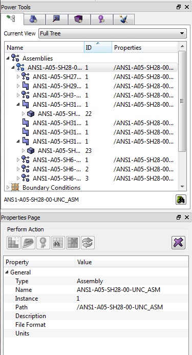
Metadata may be displayed and manipulated in the GUI. The tree view includes a category for metadata. The category is labelled "Assemblies" in the tree view. Users are able to drag volumes into parts on the tree. Also, selecting an Assembly or Part on the tree will cause the attributes for the entity to be displayed in the property page where further data manipulation is enabled.