
Cubit 15.2 User Documentation
Mesh Scaling is a tool to globally refine or coarsen a hexahedral mesh, while avoiding the 8X multiplier required by template-based global refinement methods. Mesh Scaling works only on all-hex meshes.
Template-based refinement methods replace each element in the mesh with a 2x2x2 template of hexahedra, resulting in an 8X element count increase. In contrast, Mesh Scaling decomposes the mesh into locally structured and swept sub-blocks, often called the block decomposition. Blocks in the decompositions span over element boundaries, stopping only at the non-swept mesh singularities (i.e. non-4-valent nodes and edges), and geometric, boundary condition, and loading constraints on the mesh. Mesh Scaling then remeshes the entire model conforming to the blocks in the decomposition, using the original mesh as a sizing function, multiplied by the scale factor.
Mesh Scaling allows a series of meshes to be built, each of which contain similar mesh structure, which can be used for solution verification. For example, if input mesh has 10,000 hexahedra, scaling with a multiplier of 2.0 will result in a mesh with approximately 20,000 hexahera, that also has the same element orientation and approximate element sizing gradations as the original mesh. Additional meshes can be built by scaling the original mesh again with multipliers of 4, 6, 8, etc. to generate a series of meshes. This series of meshes can then be used for solution convergence studies at a computational cost much less than if traditional global refinement is used.
The syntax to scale a mesh in Cubit is:
scale mesh [volume <ids>] [multiplier <double>] [minimum <int>] [{SWEPT_BLOCKS|structured_blocks}] [feature_angle <value>] [force_structured in {[volume <ids>] [surface <ids>]}]
Specifying a list of volumes to scale is optional. If no volumes are specified, all volumes meshed with hexahedral elements will be scaled. If one or more volumes are specified, Mesh Scaling will alter the mesh in the specified volumes plus any other volumes which are merged with the specified volumes, recursively. This allows scaling of individual assembly components, without scaling the entire model.
The multiplier parameter specifies the target number of hexahedral elements to be in the mesh after mesh scaling. If not specified, the default value for multiplier is 2.0. The locations of the new nodes on the boundary of the mesh created during scaling will be projected to lie on the associated CAD geometry. For example: Figure 1 illustrates an all-hex mesh associated to a CAD model with 3025 hex elements. Figure 2 illustrates the mesh after scaling with a multiplier of 2.0, resulting in 6804 hex elements. Note that the Scale Mesh command attempts to match the requested multiplier as close as possible, but there is no guarantee it will match it exactly.
Figure 1. Input mesh for Mesh Scaling. The mesh contains 3025 hex elements.

Figure 2. The mesh from Figure 1 scaled with the command "Scale Mesh Multi 2". The resulting mesh contains 6804 hex elements.
Mesh Scaling decomposes the mesh into a block decomposition composed of either "Structured" or "Swept" blocks. Structured block are locally a MxNxO locally structured mesh. Mesh Scaling increases or decreases M, N, and O by small amounts to perform scaling, until the desired multiplier is reached. For example, a structured block that is originally 3x4x10 may get scaled to 4x5x12 distributing the refinement in all 3 directions.
Swept blocks are locally single-source-to-single-target sweeps with a source meshed with quad elements, which are swept any number of layers forming hex elements along the way. Each quad on the source forms a column or stack of hex elements along the sweep. Mesh Scaling remeshes the source surface with a new quad mesh using a sizing function derived from the original mesh on the source multiplied by the scale factor. The new mesh on the source is then swept a new number of layers which is the old number of layers multiplied by the scale factor.
Users can control what type of blocks are constructed in the block decomposition by using the swept_blocks or structured_blocks options. If swept_blocks is specified, the block decomposition will put swept blocks in regions where sweeps can be identified, and structured blocks everywhere else. If structured_blocks is specified, structured blocks will be added everywhere. In general, using swept_blocks will give you a smoother, more evenly distributed refinement when compared to using structured_blocks. This is because by specifying swept_blocks, there is typically a big reduction in the number of blocks in the decomposition. With more blocks in the decomposition, the requested scale factor is often reached before all of the blocks get any refinement, especially for smaller scale factors. This results in regions of the mesh that appear to have no change. In contrast, with swept_blocks, there are typically significantly fewer blocks in the decomposition, increasing the likelihood that all blocks will recieve at least some refinement. However, using the structured_blocks will result in a mesh with element orientations closer to the original mesh. This is because structured blocks are bound to maintain any mesh singularity in the mesh (i.e. an internal edge in the mesh with something other than 4 hexes attached). Specifying swept_blocks does not maintain all mesh singularities, rather they are incorporated into sweptblocks, and remeshing of the source surface may introduce a different set of mesh singularities.
The creation of swept blocks is the default if nothing is specified.
In some cases, the user may want to turn on sweptblocks for some of the model, while turning it off for other parts of the model. If the original mesh was constructed with considerable care given to build a structured mesh in a few small regions, turning on swept_blocks can destroy the carefully added structure, replacing it with a pave-and-swept mesh. This can be avoided by using the force_structured parameter. For example, Figure 3 illustrates a mesh with 2 highlighted surfaces. Surface 34 was meshed with paving. In constrast, surface 108 was meshed with great care from the user to ensure a very structured mesh around the holes. However, the mesh on surface 108 does have some mesh irregularities, and the adjacent hex element structure is a swept mesh. Therefore, by default, Mesh Scaling will detect this as a swept block. Figure 4 illustrates the mesh you will get with the command "scale mesh multi 2". Notice that the carefully constructed structured mesh around the holes has been replaced with a standard paved mesh.
Figure 5 illustrates the mesh from Figure 3 scaled using the force_structured option. In this case, "scale mesh multi 2 force_structured in surface 108" was specified, allowing the mesh on surface 34 to be scaled with a new paved mesh while allowing structured blocks to be used near surface 108. Optionally, we also could have used the command: scale mesh multi 2 force_structured in volume 1, although this would result in maintaining all irregular nodes in both surface 108 and 34, resulting in more blocks, and thus a less smooth result.

Figure 3. Input mesh for Mesh Scaling. Surface 108 contains a non-mapped, but still structured mesh. Surface 34 contains a paved mesh.
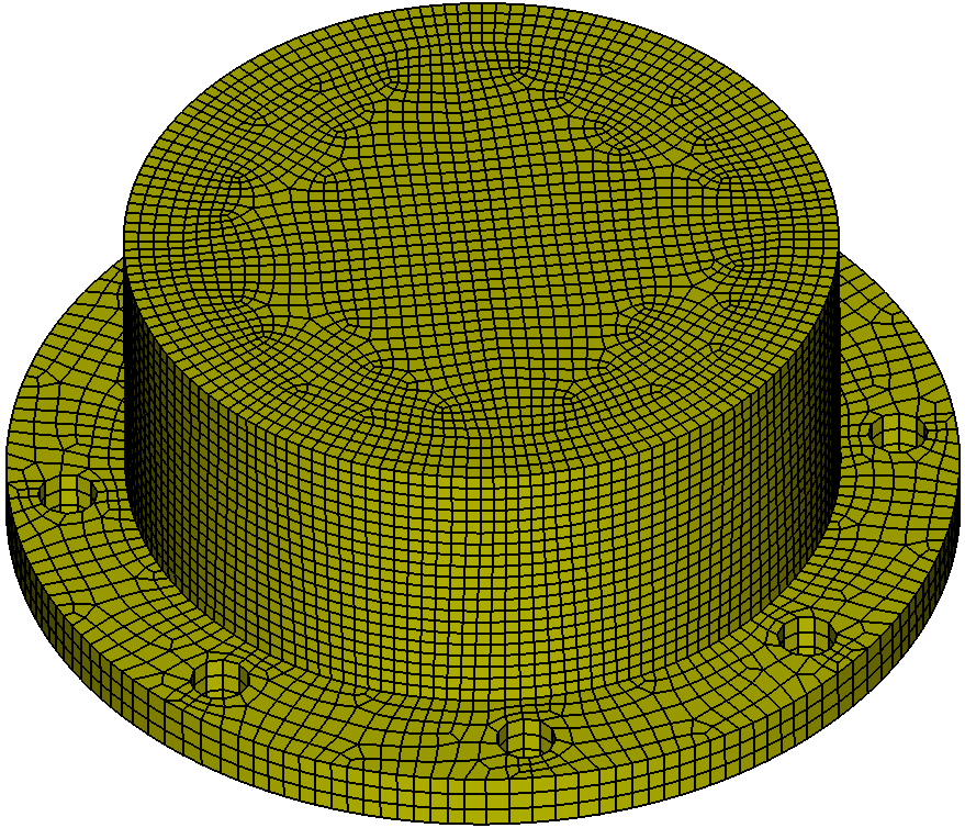
Figure 4. The mesh from Figure 3 scaled with the command "Scale Mesh Multi 2". The structured mesh on surface 108 is replaced with a paved mesh.
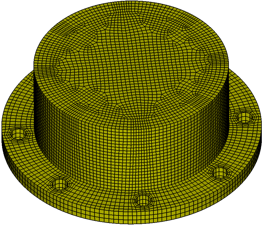
Figure 5. The mesh from Figure 1 scaled with the command "Scale Mesh Multi 2 force_structured in Surface 108". The structured mesh in surface 108 is maintained, while the remainder of the volume is scaled with swept blocks.
The minimum parameter provides further control allowing the user to specify the minimum number of intervals added on curves in the block decomposition. The multiplier provided to the mesh_scale command serves as the target on the number of elements in the output mesh. Mesh Scaling will output a mesh with approximately multiplier*n, where n is the number of elements in the input mesh. Depending on the structure of the mesh, for low multipliers, and if minimum=0 is specified, there is no guarantee that every block in the decomposition will be refined in all 3 directions. This is because the target number of elements may have been reached before every block in the decomposition is refined in all 3 directions, leading to the unevenly distributed refinement discussed above. To guarantee that every block will be refined in all 3 directions, the minimum parameter can be used. Specifying minimum 1 (which is the default), will guarantee that at least one element interval will be added to every element block in all 3 directions, which guarantees that the entire domain of the mesh will be scaled by at least a little bit. An uneven distribution of refinement is also the result if structured_blocks is specified when you have adjacent structured blocks that have significantly different dimensions. For example, if you get 2 adjacent structured blocks in the decomposition where the first block is 1x10x12, which is immediately adjacent to the second block which is originally 6x10x12, Mesh Scaling could remesh the blocks as 2x11x13 and 7x11x13, which is the minimum refinement that can be done ensuring some refinement everywhere. However, this leads to an unevenly refined mesh.
Mesh Scaling enables solution verification by enabling easy generation of a series of similar meshes of increasing mesh density on a model. When generating the series of meshes with mesh scaling, each mesh in the series should be generated with a multiplier at least 2X larger than the multiplier generating the previous mesh in the series. Less than this will likely not produce sufficient changes in the mesh to be significant in the solution verification. The minimum parameter can also help to ensure that each mesh changes slightly from the previous mesh in the series. A good set of (Multiplier,Minimum Interval) parameters for generating a series of meshes for solution verification is:
(2X, 1) (4X, 2) (8X, 3) (16X, 4), etc.
where each multiplier is 2X the previous multiplier and the minimum interval increase is 1 more than the previous specified. However, caution must be maintained that you do not be too aggressive with the minimum interval parameters. For example, the parameter series:
(2X, 1) (3X, 2) (4X, 3) (5X, 4) (6X, 5) (7X, 6) (8X, 7) etc.
would be too aggressive, given that the multiplier increases very slowly, while the minimum interval increases quickly. This will cause the surface paver to be forced to generate very high transitions in element size, often causing poor element quality or mesh generation failure. If you must use these multipliers, then a less aggressive minimum series is recommended such as:
(2X, 1) (3X, 1) (4X, 2) (5X, 2) (6X, 2) (7X, 2) (8X, 3) etc.
For best results, never scale a previously scaled mesh. Rather, generate all meshes in the series by scaling the original mesh using different multipliers.Coarsening can be achieved by specifying a multiplier less than 1. For example, a multiplier of 0.9 will attempt to decrease the element count by 10%. Coarsening, however, is constrained by the mesh irregularities and geometric, boundary condition and loading constraints. Thus coarsening will only be possible up to the point that these constraints can still be satisfied.